Abstract
The paper presents modelling and the process of dynamic model identification of crankshaft system. At the beginning some information about design, operation and test of crankshaft systems is shown. The next section describes the process of crank-piston mechanism with a vibration damper modelling and the method of obtaining the motion equation. The last but one section demonstrates some aspects of the process of dynamic model identification. Moreover, tests and numerical simulation are presented. At the end, there is a summary of the whole paper. Conclusions about modelling and identification of dynamic model of crankshaft systems are shown.
1. Introduction
The engineers face a difficult task because of current trends in design of modern internal combustion engines and increasingly stricter rules on emissions. It is necessary to design a drive system with a number of detailed assumptions which are often contradictory. The mass reduction of particular elements of the engine is usually the effect of all these actions. In most practical cases, it is associated with a change in the geometry or the use of modern materials in the design process.
It is clear that all changes of elements of drive system can change the behaviour of dynamics and statics of a given object. Moreover, it is likely that there may appear a significant change in the spectrum of the whole device. Thus, there arises a question about the changes of the spectrum of device vibrations when the constructional changes are introduced. Positive answer gives new possibilities of forming spectral structure of a given machine.
Modification of the vibrational structure, in many cases technical ones, is implemented by the use of a damper of torsional vibrations. It is widely known that such a device is a dynamic vibration eliminator. The changes of basic frequencies of vibrations of the whole engine result directly from the principle of working of a damper. However, without a detailed analysis it is impossible to predict how the spectrum of vibrations will look like after applying a damper of vibrations. Furthermore, in practice, the use of torsional vibration eliminator influences the remaining degrees of freedom because of lateral-torsional coupling. This problem is especially important in the case of car engine crank systems with high power, where torsional vibration dampers are often used.
Selection of parameters of such a damper is relatively difficult. As previously noted, it is necessary to make a detailed analysis of a discussed engine, including a chosen technique of vibration elimination. For this purpose, it is important to use a dynamic model (the simplest in this case) of drive system. Unfortunately, due to the multitude of construction details of this type of device, it is not possible to determine all parameters of such a model directly. Of course, it is possible to attempt to make a very detailed modelling of the system. However, in practice it usually does not improve the quality of obtained results. In such cases, it is much more convenient to identify a model [1] with a high degree of abstraction rather than analyse a very detailed system of dynamics equations [2, 3].
2. Dynamic model of crank system
Despite its apparent simplicity, the crank system is a mechanism with very complicated dynamics. It involves the deformability of all elements of its component, a nonlinear geometry of movement and of a very complex nature of the load of the crankshaft. Theoretically, the whole should be treated as a set of mutually interacting continuous systems described with distributions of density and stiffness tensor.
It turns out, however, that for the reasons mentioned earlier this solution is not feasible in practice. It is much simpler to present this mechanism as a series of stiff elements (material points or rigid bodies) connected by massless continuous system. The errors resulting from the assumed simplifications will be eliminated in the identification of a dynamic model which is discussed. The analysed crank system may be presented in the following way:
Fig. 1The model of the crankshaft of one piston: 1 – flywheel, 2 – crankshaft, 3 – torsional vibration damper
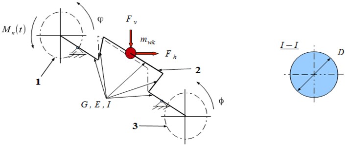
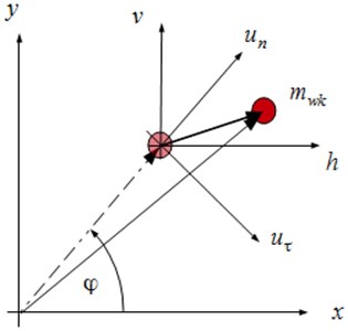
The following system of generalized coordinates is introduced to the proposed model (Figs. 1 and 2): – rotation angle of flywheel of the engine, – rotation angle of the disk of torsional vibration damper, –horizontal deformation of the crank, – vertical deformation of the crank.
Fig. 2Crank of shaft global displacement
Due to high stiffness of crankshafts used in automotive, it is possible to simplify the use of small deformations of the object, and as a result, of the linear elastic model. In such a system the relation between vector of generalized forces and the displacement vector is linear. Moreover, Clappeyron systems theory shows that these relations may be presented as follows:
or more generally:
Theoretical considerations show that dependencies in the considered segment of crank system Eqs. (1)-(4) will simplify. Some elements of stiffness matrix will be zero for the assumed system of forces and moments:
The interaction of gas forces and piston inertia in the assumed model of crank system is shown as a system of forces affecting the crank.
3. The general form of the equations of motion of the crankset with a torsional vibration damper
The previous considerations show that a seemingly simple mechanism, which is the crank system, is characterized by a very complicated mechanical structure. The main cause for this, is strongly nonlinear geometry of motion of individual elements of a discussed object. Obviously, obtaining equations of motion of this system is not simple, especially with the use of balance methods (vector methods). It is much more convenient to use formalisms of analytical mechanics, such as Lagrange or Hamilton formalism. The experiments show that in the case of mechanical systems with holonomic constraints (in the analysed problem all constraints are geometric) the Lagrange equations of second kind are very effective.
The formalism of Lagrange equations is based on the analysis of the system and total kinetic and potential energy. This is especially convenient because of the simplicity in determining mechanical quantities. Having calculated the individual parts of Lagrange formalism, the following equations of motion of the analysed crankset are obtained:
where: – vector of generalized coordinates of torsional vibration damper, – inertia matrix of torsional vibration damper, – operator of the right side of equation of dynamics of torsional vibration damper.
4. The problem of identifying a dynamic model
The model of dynamics of the crankset may describe the dynamics of a real crank system [4]. It happens under the condition of precise determining its particular parameters. There does not exist the possibility of direct measurement of unknown quantities because of the simplifications used in the model. Therefore, such a model would be worthless in structural or diagnostic applications. The only effective method to enforce the compliance of theoretical and experimental results is the identification of a dynamic model. The parametric identification (one in which the structure of the model is precisely determined) can be defined as follows:
where: – a model solution, – the result of the experiment, – the selection operator in time domain, – permissible total error of identification process.
The use of selection operator in time domain is necessary because of the existence of additional information present in the measurement, which is not connected with the identified model. The transformation of Eq. (11) to the frequency domain is also possible:
where: – the result of the experiment, – selection and averaging operator in frequency domain.
Dependencies Eqs. (11) and (12) make no sense without defining the relevant metrics. It is convenient to define the distance in time and frequency domain in the following way:
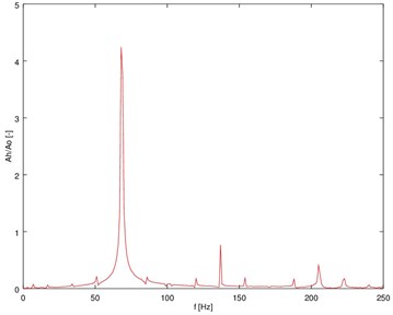
Making a comparison of theoretical solution (Fig. 3) with the results of experiments (Fig. 4), the unknown parameters of discussed system in the process of parametric identification are designated.
Fig. 3The spectrum of transverse vibration accelerations of the model of crank system
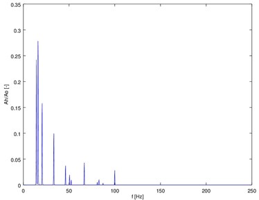
Fig. 4The registered spectrum of transverse vibration accelerations of the body of a car engine
5. Conclusions
Modelling of crank system dynamics is very difficult. The main problem is the “accuracy” of the model. It is possible to propose a very complex model, the analysis of which will be very difficult, or a model simple in construction and analysis. On the other hand, it is easier to identify individual elements of the system for more advanced modelling. However, for models with a high level of abstraction such a process may not be directly feasible because of generality of this research. For this reason, it is worth to make an identification process of a dynamic model.
The paper presents the numerical solution of the analysed model of crank system and the results for the real object. Furthermore, there were described the details of the process of “tuning” of the considered system of equations.
Bending-torsional coupling of vibrations present in the model is the reason for a complicated frequency structure of the analysed object. Moreover, it is possible to use this phenomenon in practical applications.
The model proposed in the paper, identified on the basis of experiments, may serve as an important tool in the design process of systems eliminating vibrations and the measurements of engine vibrations. It can also serve as a valuable source of diagnostic information about the technical condition of piston engines, in particular torsional vibration dampers [5].
References
-
Batko W., Dabrowski Z., Kiciński J. Nonlinear effects in technical diagnostics. Radom ITE-PIB 2008.
-
Chiliński B. Analysis of bending and torsional vibrations of rotors with using perturbation methods. The PCM-CMM-2015, (in Press), 2015.
-
Chiliński B. Analysis of disturbance torque influence on critical state in rotational systems. Transportation Problems, Vol. 8, Issue 4, 2013, p. 137-146.
-
Dabrowski Z., Zawisza M. Investigations of the vibroacoustic signals mechanical defects sensitivity is not recognized by the OBD system in diesel engines. Solid State Phenomena, Vol. 180, 2012, p. 194-199.
-
Deuszkiewicz P., Pankiewicz J., Dziurdź J., Zawisza M. Modeling of powertrain system dynamic behavior with torsional vibration damper. Advanced Materials Research, Vol. 1036, 2014, p. 586-591.
About this article

