Abstract
Operational Modal Analysis (OMA) method is very often used for the identification of mechanical parameters of engineering structures. This method can be applied under the assumption that the excitation acting on the tested system is random. This requirement is not met in case of some industrial machines (e.g. in power engineering) while the excitation related to rotating elements significantly worsen the accuracy of modal models estimated by means of the OMA methods. Therefore the methods making it possible to overcome this problem arise great interest. One of such methods is OMAX that nowadays is more and more frequently applied to operational identification of mechanical structures. The paper concerns comparison of the classical methods (OMA) and OMAX method. The results were verified experimentally for the characteristics measured on the laboratory object and on the wind turbine.
1. Introduction
Rotating machines play a vital role in modern economics. Most industrial processes where energy is processed are based on rotating machinery. Thus, it is increasingly important to maintain those machines in the good technical state. Main drivers for final users are:
– avoidance of catastrophically failures,
– decrease of maintenance costs,
– increase of availability.
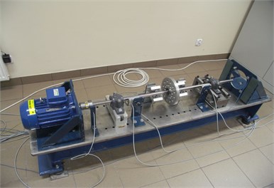
This needs, in turn, create strong demand for diagnostic techniques. Theoretical works are performed since decades, starting from simplified, linear rotor models. With advances in rotordynamics research new processes were identified and described. Recently the model-base diagnostic techniques become more and more popular [1]. In the paper the proposal of rotating machinery diagnostic system base on OMA(X) [2, 3] methods is presented. The proposed algorithm has been tested on laboratory test rig (Fig. 1) and on data collected at wind turbine.
Fig. 1AGH laboratory test stand
2. System architecture
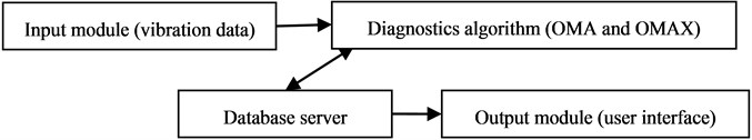
General turbine diagnostics system architecture [3, 4] is presented in Fig. 2.
The first module – input module – is the standard acquisition system mounted at monitored object. There is no need to build in a special system for proposed diagnostics algorithm. In the second module there are all proposed algorithms – OMA and OMAX. This module estimates the modal parameters of monitoring object – natural frequencies and modal damping ratio using both methods. In this module there is also detection if the synchronization has happened. In the case of synchronization the OMAX algorithm is used, during normal work of turbine the on-line OMA algorithm is used. The database server is used for storing raw data from vibration sensor (time signals), reference data from undamaged state and mode shapes estimated during the diagnostics procedure. The output module is used for presenting diagnostics data – the mode shapes of monitoring object. In the user interface there also be FFT charts with current and reference vibration spectrum. The architecture presented above should be implemented to reuse existing technology. It is planned to: use standard “off-the-shelf” hardware to acquire vibration signals, implement diagnostic algorithms and store the results in the existing platform.
Fig. 2Monitoring system architecture
3. Diagnostics algorithm
The general scheme of proposed monitoring system algorithm is presented in Fig. 3.
Fig. 3Scheme of proposed diagnostics algorithm
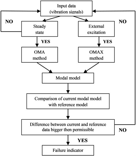
The first step of proposed algorithm is the preparation of input data. For operational modal analysis ones need to use time signals with at least 90 sec lengths. The lengths of time signal determined the spectral resolution of FFT and have a influence of accuracy of natural frequency detection. Because proposed algorithm should be executed one time at hour we proposed to use 10 [min] length time signals. This signals should be sign in the system database and after it use off-line to estimate a monitored object modal parameters. The next step of algorithm is detection of synchronization moment or steady state work. If during the signal recording the synchronization takes place the system automatically switch to OMAX algorithm if not – to OMA algorithm. We cannot use the same algorithm for data from moment of synchronization and without it because the another mode shapes can be found in this two cases. The third step of diagnostics algorithm is the modal parameters estimation. In this stage the natural frequencies and modal damping ratio in chosen frequency range of object are calculated. There is important to distinguish data from displacement sensors and accelerometers. The algorithm should be executed sequential – first for displacement sensor and then for accelerometers. After this step we received two sets of modal parameters – one set for displacement sensor and second for accelerometers – which are recording in system database.
4. Experimental results
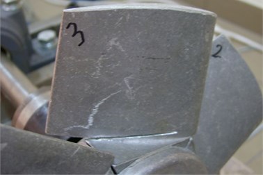
The proposed turbine monitoring system has been checked in the case of blade crack detection. The test rig was modified by mounting the blades at the end of the shaft. Then a crack of a blade was introduced (Fig. 4).
Fig. 4Simulation of crack at blade
Diagnostics algorithm based on OMAX method for blade crack detection can be summarized as follows:
– estimation of 1st natural frequency of blades,
– excitation the vibrations of blades during the normal work of test rig with using the electromagnetic exciter (excitation signal – sinus with frequency of 1st natural frequency of blades),
– measurement of vibration accelerations on bearing covers,
– estimation of modal parameters of investigated object.
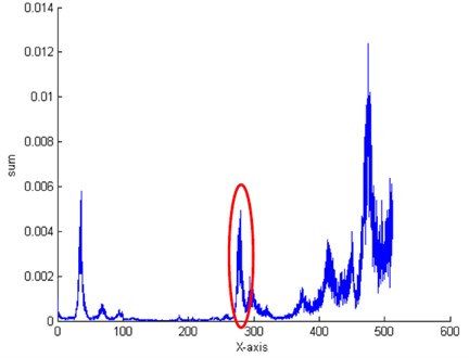
The FRFs recorded at blade and bearing covers are presented in Figs. 5 and 6. Analysis of these FRFs clearly show that using of electromagnetic exciter allow to excite the 1st natural frequency of investigated blades and measure it by accelerometer placed on bearing cover. Experiment results clearly show that introduced a crack on one of the blades caused the changes in natural frequencies of investigated object (good blade – 287.54 Hz, crack blade – 280.16 Hz). The value of 1st natural frequency of blades decrease about 3 % (about 7 Hz). This change of 1st natural frequency of blades show that one of blade has failure and this change can be use as failure indicator in blade crack detection algorithm.
5. Verification of proposed diagnostic algorithms on real data
The last stage of proposed algorithms testing was done on real data collected on wind power plant turbine. Data were collected by a typical time signal recorder mounted at the object. Unfortunately during the experiments there was no possibility to use an external excitation so we were only able to verify the algorithm based on OMA method. We couldn’t use the OMAX algorithm for this data.
Fig. 5FRF of damaged blade
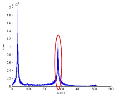
Fig. 6FRF recorded by accelerometers placed on bearing cover
During the whole experiment the object was in the same condition so we can check only the reliability of proposed algorithms. In the OMA approach data processing was performed in Matlab and dedicated toolbox VIOMA. The modal parameters of object were estimated by using BR approach. The goal of the investigation was to detect how reliability is the diagnostics algorithm based on modal technique for data collected in nonstationary condition. In Table 1 the modal parameters for this cases are presented.
Table 1Natural frequency (NF) and modal damping (MD) detected using OMA method for data from various dates
No. | 2007-06-15 | 2007-06-16 | ||
NF [Hz] | MD [%] | NF [Hz] | MD [%] | |
1 | 24.98 | 0.36 | 24.99 | 1.03 |
2 | 60.11 | 0.43 | 60.24 | 0.49 |
3 | 89.62 | 1.67 | 89.47 | 1.92 |
4 | 92.90 | 2.06 | 92.28 | 1.28 |
5 | 105.18 | 2.06 | 105.28 | 1.72 |
6 | 120.67 | 0.30 | 120.82 | 0.50 |
6. Conclusion
Experimental results clearly show that OMA(X) method can be successfully implemented in rotating machinery diagnostics. On-line monitoring systems can base on these two methods. In this case, for power plant components, as external input for OMAX method a moment of turbine synchronization can be used. There is also a possibility to use as external excitation an electromagnetic device. One of the most important advantages of this method is possibility to use them in blade crack detection. Cracked blade can cause a catastrophically failures in turbo machinery [5] so it is very important to find the crack in early stage. Proposed algorithm based on OMA(X) method allows to check every blade separately and significantly increase the safety of turbine. Presented results proved applicability and advantages of OMA(X) method and in model based structural health monitoring of rotating machinery.
References
-
Natke H., Cempel C. Model – Aided Diagnosis of Mechanical Systems. Springer, Berlin, 1997.
-
Cauberghe B. Applied Frequency – Domain System Identification in the Field of Experimental and Operational Modal Analysis. Ph.D. Thesis, VUB, Brussel, 2004.
-
Bednarz J., Barszcz T., Uhl T. An example of application of model-based approach to SHM of rotating machinery. Proceedings of the Third European Workshop on Structural Health Monitoring, 2006, p. 1329-1336.
-
Barszcz T. Monitoring and Diagnostics of Machines. Institute for Sustainable Technologies, PIB, Kraków, 2006, (in Polish).
-
Orłowski Z. Diagnosis in the Long Term Operation of the Steam Turbine. Scientific and Technical Publishing House, Warszawa, 2001, (in Polish).
About this article

