Abstract
The article presents the dynamic strength analysis hub rubber torsional vibration damper. Numerical calculations were performed in the finite element method using commercial software Abaqus using explicit dynamic approach. Numerical simulations consisted of two calculation steps: the first was modeled pre-tension bolts at the second step hub was subjected to the action of a torsional vibration harmonics of predetermined amplitude and frequency coming from the shaft.
1. Introduction
Torsional vibration dampers are used wherever there is a concern that the amplitude of torsional vibrations parts exceeds the limit values, thereby reducing the fatigue strength of the structure. Commonly torsional vibration dampers are used for vibration damping of torsional crankshaft multi-cylinder internal combustion engines which are an essential part of powertrain modes of transport. In internal combustion engines used to power cars vehicles are used small-sized rubber dampers that are placed (screwed) on the free end of the crankshaft [1-3]. Detailed experimental research of dampers, designed to find the distributions of stress and strain during their operation are complicated and expensive, mainly due to the difficult access to the working elements, and the need for complicated equipment. Stress and strain distributions of selected elements of the damper can be found in the following competently made dynamic numerical simulations [3, 4]. Essential issue is correct modeling of contact conditions between cooperating elements. Numerical simulations operating torsional vibration damper can be efficiently performed in the finite element method using an explicit dynamic approach, which is particularly useful for analyzing rapidly changing loads. Obtained by a numerical simulation test results can be verified by using Photoelasticity, which allows for the distribution effort of both the real machine parts and created on the basis of models made, among others, rapid prototyping RP techniques (called Rapid Prototyping) and RT techniques (called Rapid Tooling), in particular by casting in silicone molds (VC. Vacuum Casting).
The biggest advantage of photoelastic research is a possibility for load as close as possible to the actual conditions in which analyzed element is working [5, 6].
2. Simulation of the vibration damper (FEM)
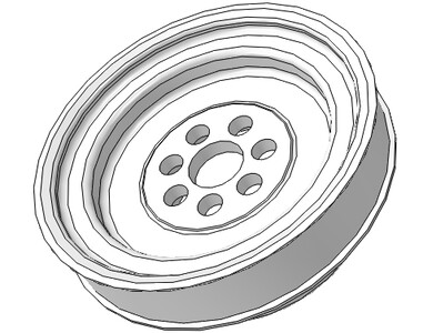
The subject of discussion was the small-dimension rubber torsional vibration damper. The simplified geometry of the hub of the damper is shown in Fig. 1. In geometry have missed some construction details like “Furrows” on the pulley.
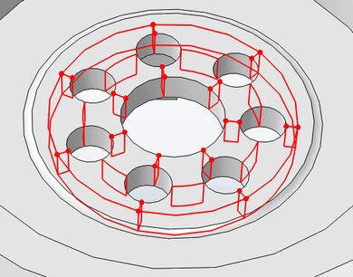
However, static calculations or modal analysis of hub for shown geometry do not present much of a problem for the average personal computer PC, dynamic explicit approach [7] to carry out effective calculation requires extra simplification and modification of the geometry of the hub. As it is known, this approach is conditionally necessarily [8], and a stable increase in the analysis time depends on the characteristic size of the smallest finite element used. This forces to eliminate the fine details of the geometry, e.g. the type of small fillets and chamfers, which are the cause generation of small finite elements. Previous static calculations have shown that the highest stress levels in the hub are in the vicinity of the screws by means of which the hub is screwed to the shaft. In these areas have been additional divisions geometry (i.e. partition) so that in these areas it was possible only generation hexagonal elements. The rest of the area were meshed by tetrahedral elements of the constant strain/stress – in explicit dynamic approach cannot be used elements of higher orders due to improper weight distribution modeling. Partitioning the central part of the hub is shown in Fig. 2.
Fig. 1The simplified geometry of the hub damper

Fig. 2Partitioning the central hub portion

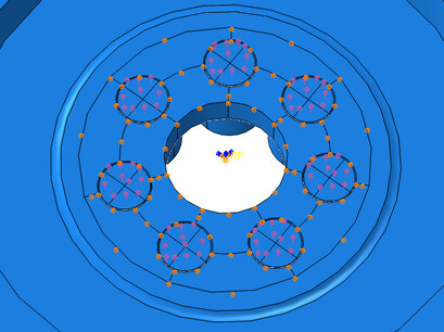
Fig. 3Load of damper hub

Rubber damper element was not modeled in the numerical calculations. For the hub and screws assumed linearly elastic material model. Contact modeled as frictionless or as a contact with friction. The load was applied in two steps. In the first step modeled preload bolts. Tension in bolts was increased monotonically. In the second step, the reference point located in the center of the dial rigidly connected to the ends of the screws (Fig. 3) imposed kinematic load in the form of harmonic torsional vibration of predetermined amplitude and frequency corresponding to actual working conditions of the damper.
Despite the best efforts involving the geometry simplification and continued its partitioning, designed to generate nets FEM without small elements, in the outer region of the hub always appeared a few small finite elements. As a result, stable increase time was not an acceptable level of 10-9-10-10 seconds. To increase the value of stable increase in the same time and reduce the computing time used a technique called scaling the mass. In critical (the smallest) components, the program automatically increased density which resulted in significant increase of stable increase in time to level 10-7 s. The mass of the entire damper slightly increased by a fraction of a percent. Mass scaling technique is often used in case of problems with too small value stable increase in time.
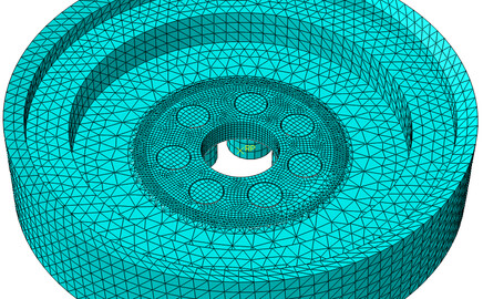
Net FEM model is shown in Fig. 4.
Fig. 4Net FEM model of hub damper

3. Numerical calculations results
Dynamic calculation of the torsional vibrations of small-dimension torsional vibration damper shown that the dominant stresses in the hub damper are stresses from the bolt pressure. Their values are significant and may reach 400 MPa – Fig. 5. Found schedule of reduced stresses by Huber-Mises hypothesis qualitatively correspond to the images of the studies photoelastic (isochromatic lines are images of reduced stress distribution Treska criterion).
Fig. 5Reduced stress [MPa] on the hub damper coming from the heads of the fastening screws hub damper
![Reduced stress [MPa] on the hub damper coming from the heads of the fastening screws hub damper](https://static-01.extrica.com/articles/16534/16534-img5.jpg)
Fig. 6Reduced stress on the hub damper [MPa] with periodically variable extortion
![Reduced stress on the hub damper [MPa] with periodically variable extortion](https://static-01.extrica.com/articles/16534/16534-img6.jpg)
Fig. 7Distribution of the reduced stress on the hub damper [MPa] by applying to periodically variable
![Distribution of the reduced stress on the hub damper [MPa] by applying to periodically variable](https://static-01.extrica.com/articles/16534/16534-img7.jpg)
The introduction of additional torsional vibration of the hub by screws threaded into shaft resulted in a slight perturbations of stress distribution in the hub directly in the area of the screw hole – Figs. 6, 7 uneven distribution of stresses in the holes of the hub after its thickness occurs when vibration contributes to ovalization of openings and premature wear of the damper. This effect will be enhanced by vibrations of the shaft of greater amplitude. There were no significant differences in the distributions of stresses in the frictionless model and the model with Coulomb friction.
4. Conclusions
Numerical simulations presented in this paper allows for detailed investigation of the stress distribution in service of the small-dimension hub rubber torsional vibration damper. Numerical tests have shown that stresses resulting from fastening screws are dominant. Stress perturbations occurred in the damper torsional vibrations cause ovalization of openings and premature wear of the damper. The results of FEM analysis should be always – if possible – compared to the experimental data. Obtained stress distributions are compatible to the results of photoelasticity investigations (not presented here).
References
-
Homik W., Skrzat A. Analysis of the strength torsional vibration damper with internal damping. 23th Fundamentals of Machinery Design Symposium, Rzeszow, Przemyśl, 2007, (in Polish).
-
Homik W. The torsional vibrations of crankshaft in engine with rubber torsional damper. XVIII International Conference – SAKON, Numerical and Experimental Methods in Development of Cars and Working Self-Propelled Machines, Rzeszow, 2007.
-
Homik W. Damping of torsional vibrations of the crankshaft multi-cylinder internal combustion engine. Transportna Akademia Ukraini. Praci Zachodnowgo Naukowo Centrum, 2007.
-
Homik W.Skrzat A. Analysis of work torsional vibration rubber damper of engine crankshaft. Western Scientific Centre of Ukrainian Transport Academy – Transportna Akademia Ukraini. Praci Zachodnowo Naukowo Centrum, 2008.
-
Kopecki H. Problems analysis states stress the system in view of experimental methods of mechanics model. Zeszyty Naukowe Politechniki Rzeszowskiej, Mechanika, Vol. 78, 1992.
-
Kopkowicz M. Experimental methods of research design. Oficyna Wydawnicza Politechniki Rzeszowskiej, Rzeszów, 2003.
-
Rakowski G., Kacprzyk Z. Finite element method in engineering construction. Oficyna Wydawnicza Politechniki Warszawskiej, Warszawa, 2005.
-
Bathe K. J. Finite Element Procedures. Prentice Hall, Upper Sadle River, 1996.
