Abstract
This article presents a method of modeling small-dimension rubber torsional vibration damper using MATLAB/Simulink, mathematical model of the damper and simulation studies. This model can be used to define the characteristics of damper before the step of designing the mechanical structure and provide guidance for the design. A crucial design parameter dampers are the resonant frequency of the damper that needs to be matched to the frequency of the common load conditions. Using the simulation methods, it is possible to determine the response of the typical damper force of varying amplitude and frequency enforces. To speed up the process of determining a resonance frequency used method which involves the use of a signal simulation forcing in the form of white noise. After determining the resonant frequency to the model, a signal inducement was given in the form of a sinusoidal force at a predetermined frequency, making it possible to determine the amplitude of the vibration damper.
1. Introduction
Rubbery damper often called vibration eliminators (Fig. 1) [1-9], modeled as a two-mass systems (Fig. 2).
Fig. 1Construction of torsional vibration damper with internal damping
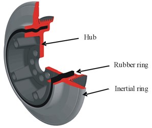
Fig. 2Model of rubber torsional vibration damper
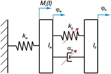
These masses are connected by elastic-damping element (, ). Periodic extortion is applied to the mass and connected to an elastic element . The other end of the elastic element is firmly established, corresponding to the node of the first embodiment of torsional vibration. This model describes the system of two differential Eq. (1) generally nonlinear:
where: – replacement moment of inertia of the shaft and hub, – mass moment of inertia of pellet, – replacement stiffness of shaft, – extortion, , – angular displacement shaft and hub of damper and pellet, and: – stiffness characteristics of the rubber damper, – damping characteristics of the rubber damper, , , – the stiffness factor of “linear” part of resilient characteristics of the damper, – the stiffness factor of “unlinear” part of resilient characteristics of the damper depended on exponent , – damping factor of the “linear” damping characteristics, – damping factor of the “unlinear” damping characteristics depended on exponent
The parameters , , , , , determined experimentally under dynamic loads (from forcing harmonics) in the range of damper work [10-13]. For these conditions it shows that a proper maximum displacement and velocity relative must be small (not to exceed the limit values).
If and – damper is linear.
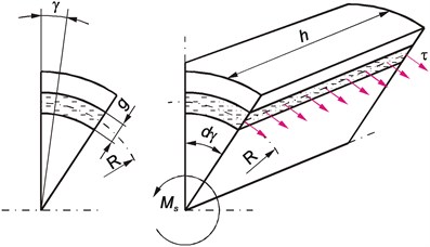
This tape of the damper dampens the torsional vibrations of the engine crankshaft to mainly to dynamic rule by creating an appropriate resonance inertial force, which balances the periodic forcing dynamic power (dynamic torque). In rubber damper physical parameters are related to the speed of deformation, the value of which is inextricably linked to the relative movement between the hub and the inertia ring. In case of exceeding a certain relative amplitude of the torsional vibration pellet, there is a relatively large torque . The moment makes the rubber is stress (Fig. 3) and are in the shear stress [14, 15] value of which is dependent on the radius under consideration of the rubber layer.
Assuming that the sectional area of the rubber is a rectangle with a side (which is a simplification), the shear stress is equal to:
where: – shear stress, – cross-sectional area of rubber, – torsional moment, – radius of the present rubber layer, – width of the rubber ring.
Fig. 3Distribution of shear stress in the rubber layer
2. The simulation model
Based on the equations identified above were implemented simulation model. The input data to the model, the following parameters are divided into groups. The first group of parameters extortion:
– The moment inducement,
– White noise,
– Extortion sinusoidal.
Torque inducement as a parameter is directly related to the amplitude of the vibration damper during operation. White noise was used to impact attenuator at all possible frequencies simultaneously. In contrast to the long-term tests on real property consisting of gradual increase engine speed and study the behavior silencer, the advantage of this method is fast possibility to determine the response of the damper, with limited computational resources, as well as shortening the simulation time. The other critical operating parameters of the damper which is the vibration amplitude was determined by a sinusoidal force, the frequency of which the user must set in accordance with a certain predetermined resonance frequency.
The second group of parameters that can be set by the user are a constant related to the geometry of the damper and the properties of the materials used in its construction, including: Output parameters include: , , , , , ,
– – angle of rotation of the shaft,
– – angular displacement pellet.
– – relative movement,
– frequency spectrum angle of rotation of the shaft.
Later a model connecting the inputs of the output parameters based on the system of Eq. (1). This model is shown in Fig. 4.
Fig. 4The simulation model of the rubber vibration damper
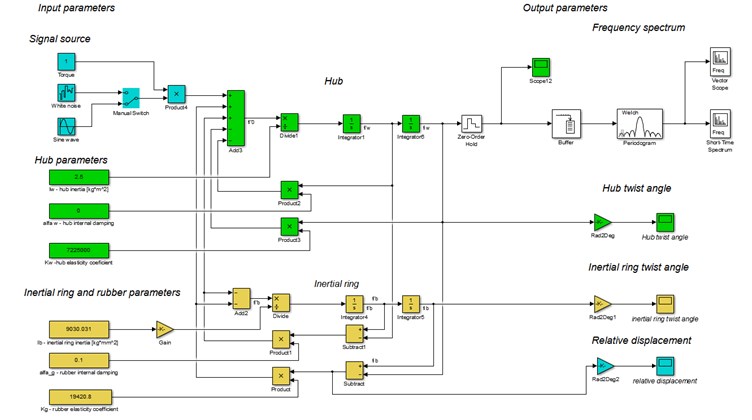
The difficulty in determining the parameters of the damper consists of, among others, a large number of input that will affect its properties. However, there are limitations due to the physical characteristics used in the construction damper materials. Therefore, in the first place should be given to the model material parameters resulting from the proposed to build the damper shaft material and used rubber (, , , ). After this step should be chosen moment of inertia of the shaft, which parameter will result from the geometry of the system to which the damper is to operate. Then, specify parameters pullet in such a way as to achieve the desired resonant frequency. These parameters are configurable by the user.
3. Examples of simulation results
The study assumed simulation parameters, which were obtained by carrying out tests of actual damper. Such an assumption was to validate the mathematical model and simulation. Accepted parameters are: 2.5 kgm2, 0, 7.225 106 Nm/rad, 0.00903 kgm2, 0.1 Nms/rad, 19420.8 Nm/rad.
First adopted constraint in the form of white noise. Fig. 5 shows the system response to this signal inducement.
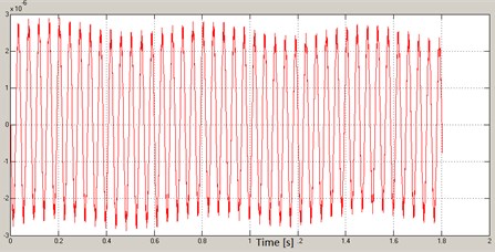
The resonant frequency of the system marked around 270 Hz can be clearly seen. The designated frequency (resonant frequency) was used in the second stage for the reference oscillation with a fixed frequency in order to estimate the amplitude of the torsional vibration of the ring and pullet, and the relative displacement under resonance conditions. The results of analysis are shown in the Figs. 6-8.
Fig. 5The system response to extortion – white noise
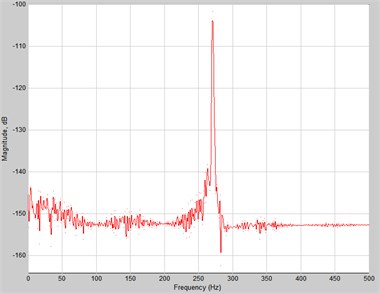
Fig. 6Shaft vibration
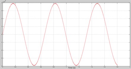
Fig. 7Angular displacement of pullet
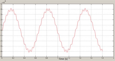
Fig. 8Relative angular displacement
4. Conclusions
Proposed mathematical model of the torsional vibration damper and developed on its basis simulation model allow to determine the important parameters of damper work. Studies of simulations showed that the rubber damper modeled in Matlab – Simulink as shown in this article reflects the behavior of the real system. Proof of this statement is determined by, among others, the resonance frequency, whose value is = 270 [Hz]. The incidence is only slightly different from frequency = 270.56340357 frequency [Hz] determined earlier during tests of drive system of car VW Passat equipped with VW’s 3.6 L FSI engine 6V containing a damper with specific model parameters during testing. Proposed method of conducting simulation tests of damper, containing, among others, white noise as inducing signal gives matching results between simulation and reality for determining resonance frequency and enables to reduce time of simulation.
References
-
Homik W. Influence of temperature changes on torsional rigidity and damping coefficient of rubber torsional vibration damper. Scientific Journal, Transport Problems, Vol. 1 Issue 1, 2011.
-
Jaroszyńska D., Gaczyński R., Felczak B. Research Methods of Physical Properties of Rubber. WNT, Warszawa, 1978
-
Patent Number 4.881.426 United States Patent. Dual-Type Damper Device.
-
Patent Number US 6.171.194. B1 United States Patent. Damper.
-
Patent Number 3.848.694 United States Patent. Torsional Damper for Motor Vehicle Drive Train.
-
Patent Number 2.477.081 United States Patent. Means for Damping Torsional Vibration in Internal – Combustion Engines.
-
Patent Number 5.449.322 United States Patent. Torsional Vibration Damper.
-
Patent Number 2.834.226 United States Patent. Torsional Vibration Damper.
-
Pankiewicz J., Deuszkiewicz P., Dziurdź J., Zawisza M. Modeling of powertrain system dynamic behavior with torsional vibration damper. Advanced Materials Research, Vol. 1036, 2014, p. 586-591.
-
Bartenev T. M., Zelenew U. V. Physics and Mechanics of Polymers. Moscow, 1983.
-
Buhina M. F. Technical Physics of Polymers. Moscow, 1984.
-
Freakley P. K., Payne A. R. Theory and Practice of Engineering with Rubber. London, Applied Science Publisher Ltd., 1978.
-
Homik W. The torsional vibrations of crankshaft in engine with rubber torsional damper. XVIII International Conference – SAKON, Numerical and Experimental Methods in Development of Cars and Working Self-Propelled Machines, Rzeszow, 2007.
-
Pankiewicz J., Zawisza M. Research of torsional vibration of the internal combustion engine’s crankshaft with various dampers (TVD). Vibroengineering Procedia, Vol. 3, 2014, p. 229-232.
-
Zawisza M. Energy loss and the choice of damper of torsional vibration combustion engines. Solid State Phenomena, Vol. 236, 2015, p. 188-195.
About this article

