Abstract
Damage to fuel system components of combustion engines significantly contributes to the deterioration of their operation dynamics, accelerates their wear and worsens the emission of toxic components of exhaust fumes. Measurements and calculations of the level of vibration and noise of a diesel engine with a damaged common rail system injector were conducted as part of the study. The impact of damage to the fuel system injector on the change in the vibroactivity of the engine during its starting was evaluated based on the calculations carried out. Time and frequency distributions of signals of vibration and noise were also calculated in order to evaluate the impact of the injection system damage on the frequency structure of vibroacoustic signals emitted by the engine.
1. Introduction
Modern compression ignition engine is required to meet strict standards of the emission of toxic components of exhaust fumes. One way to meet these requirements is to use injectors which supply fuel under very high pressure in several charges per work cycle. common rail systems make it possible to meet these requirements in compression ignition engines. However, these systems require the use of high-quality fuels with a high degree of purity. Failure to meet these requirements causes accelerated wear of injectors, decrease in the quality of the fuel stream injected into cylinders, deterioration of the combustion process and, in critical situations, damage to the engine. Damage to the injector may cause its deactivation and significant deterioration of the engine operation dynamics [1-9].
Basic systems based on engine OBD (On-Board Diagnostic) systems and external software prepared by vehicle producers and commercial companies are used to evaluate the correct operation of combustion engines [1-4]. However, these systems are dedicated to the control and diagnostics of mechatronic components of engines. In the case of first symptoms of wear or damage to mechanical components of an engine these systems adapt to the technical condition of the engine and are often insensitive to these changes [4, 10, 11].
Not all engine damage directly causes changes in electrical values measured by OBD systems. Therefore, papers [4, 10-20] propose the use of measurements and analyses of noise and vibration signals emitted by combustion engines. Owing to the development of measurement systems and signal processing methods, the development of these methods in the last several years has been very dynamic.
Measurements and calculations of the level of vibration and noise of a diesel engine with a damaged common rail system injector were conducted as part of the study. The impact of damage to the fuel system injector on the change in the vibroactivity of the engine during its starting was evaluated based on the calculations carried out. Time and frequency distributions of signals of vibration and noise were also calculated in order to evaluate the impact of the injection system damage on the frequency structure of vibroacoustic signals emitted by the engine.
2. Stand tests
The object of the study was the diesel engine of Renault Master 2.5 DCI with 88 kW and the mileage 102000 km, equipped with the common rail system.
On the test stand there were measures conducted connected with the vibration acceleration in the transverse direction to the axle of the piston movement and the direction accordant with the movement and the noise with the distance of about 0.5 m from the cover of the engine valve. During the experiments the referential signal position of the crankshaft was recorded. The measures were conducted with the sampling frequency 25 kHz. The signal transformation was conducted in the Matlab-Simulink programme.
The scheme of the piezoelectric transducers lay-out and the place of condenser microphone are presented in Fig. 1.
Fig. 1The piezoelectric transducers lay-out and the place of condenser microphone
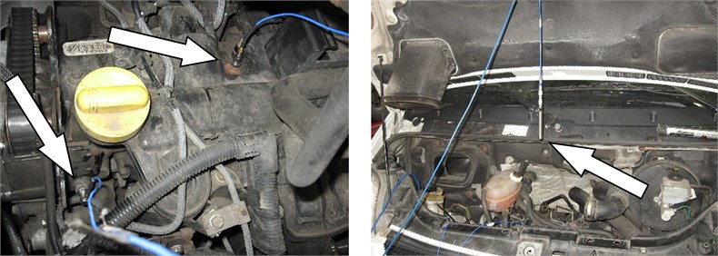
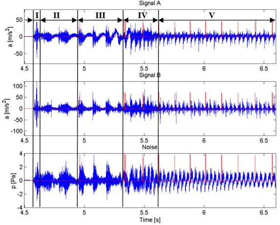
Fig. 2The recorded vibration and noise signals of the engine in a good technical condition, during the measures, where: Signal A – signal of the vibration acceleration in the transverse direction to the piston movement, Signal B – signal of the vibration acceleration in the parallel direction to the piston movement, Noise – signal of the level of the acoustic pressure near the engine, I-V – next phases of the engine start; red color – reference signal of the position of the crankshaft of the engine (the beginning and the end of the cycles of the engine work)
3. Examples of research results and their analysis
Fig. 2 shows examples of the results of vibration and noise measurements recorded during tests of an engine with a good injector. According to the presented research 4 characteristic phases of engine operation during its starting may be distinguished. These phases are described in more detail in [19].
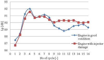
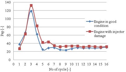
Fig. 3 shows examples of the results of calculations of an average level of sound and acoustic power [19] of an engine with an operational and damaged injector. A significant increase in the level of vibration and noise of an examined engine can be observed during its starting. It has been observed that damage to the injector causes an increase in the engine vibration level already during its starting, whereas the sound level increases after several first cycles of its operation.
Fig. 3The calculation results of the signals recorded for the engine in a good technical condition and with one injector damage, where: a) average level of the noise signal, b) average power of the vibration signal in the transverse direction to the piston movement
a)
b)
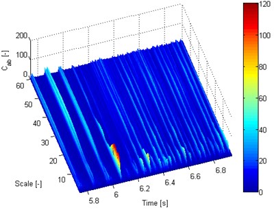
The impact of damage to the injector on the change in the vibration amplitude in time and frequency distributions was analysed in the further part of the study. Fig. 4 shows an example of the CWT distribution [20] of a vibration signal recorded when the engine was working with a good and damaged injector. The results of these analyses confirm a significant increase in the engine vibration amplitude during its starting. In the case of an engine with a damaged fuel injector, cyclically repeating amplitude increases are observed which are caused by the combustion process in three consecutive work cylinders, in the frequency scale range above 12. No vibration amplitude increase is observed in this frequency scale range at the time of the rotation of a crankshaft in which fuel from a damaged injector was supposed to have been injected.
Fig. 4Calculated time-frequency distributions of engine vibration (vibration signal in the direction transverse to the piston movement): a) engine in a good technical condition, b) engine with a damaged injector

a)
b)
4. Conclusions
Combustion engines require constant development of methods for diagnosing their condition because standard OBD systems may mask some damage and adapt engine operation to its temporary technical condition. The use of methods for the measurement and processing of vibroacoustic signals significantly expands the base of information on the temporary condition of an engine and makes it possible to perform repairs much earlier. Making a quick decision on the turning off the engine due to it poor technical condition requires evaluation of its condition already during its starting.
It was evaluated in the study how its vibroactivity level changes during starting. According to research damage to a fuel system injector causes an increase in the level of vibration and noise of an engine during its starting by several decibels. It has been demonstrated that damage to an injector causes qualitative changes in CWT time and frequency distributions, which may be used in further analyses as a new source of information for new automatic solutions for combustion engine diagnostics systems.
References
-
Ostrica L., Jurcik J. Detection of faults gasoline injection system for new OBD systems. 10th International Conference, ELEKTRO, 2014, p. 202-207.
-
Sebok M., Ostrica L., Gutten M., Korenciak D., Makyda M. Diagnostics of ignition systems. Journal of Electrical Engineering, Vol. 13, Issue 4, 2013, p. 181-186.
-
Sim A. X. A., Sitohang B. OBD-II standard car engine diagnostic software development. Proceedings of 2014 International Conference on Data and Software Engineering, 2014, p. 7062704.
-
Dąbrowski Z., Zawisza M. Investigations of the vibroacoustic signals sensitivity to mechanical defects not recognised by the ODB system in diesel engines. Solid State Phenomena, Vol. 180, 2012, p. 194-199.
-
Droździel P., Komsta H., Krzywonos L. An analysis of costs of vehicle repairs in a transportation company, part 1. Transport Problems, Vol. 7, Issue 3, 2012, p. 67-75.
-
Droździel P., Komsta H., Krzywonos L. An analysis of costs of vehicle repairs in a transportation company. part 2. Transport Problems, Vol. 7, Issue 4, 2012, p. 7-11.
-
Merkisz J., Fuc P., Lijewski P., Ziolkowski A. The on-road exhaust emissions from vehicles fitted with the start-stop system. Applied Mechanics and Materials, Vol. 390, 2013, p. 343-349.
-
Šarkan B., Skrúcaný T., Majerová Z. Possibilities of measuring the brake specific fuel consumption in road vehicle operation. Machines, Technologies, Materials, Vol. 8, Issue 5, 2014, p. 19-21.
-
Droździel P., Krzywonos L., Madlenak R., Rybicka I. Selected aspects of analyses of failure rates of active safety systems in buses. Komunikacie, Vol. 16, Issue 3, 2014, p. 114-119.
-
Dąbrowski Z., Zawisza M. The choice of vibroacoustic signal measures, in mechanical fault diagnosis of diesel engines. Solid State Phenomena, Vol. 236, 2015, p. 220-227.
-
Czech P., Mikulski J. Application of Bayes classifier and entropy of vibration signals to diagnose damage of head gasket in Internal combustion engine of a car. Telematics – Support for Transport, Communications in Computer and Information Science, Vol. 471, 2014, p. 225-232.
-
Jedliński Ł., Caban J., Krzywonos L., Wierzbicki S., Brumerčík F. Application of vibration signal in the diagnosis of IC engine valve clearance. Journal of Vibroengineering, Vol. 17, Issue 1, 2015, p. 175-187.
-
Pankiewicz J., Deuszkiewicz P., Dziurdź J., Zawisza M. Modeling of powertrain system dynamic behavior with torsional vibration damper. Advanced Materials Research, Vol. 1036, 2014, p. 586-591.
-
Dziurdź J. Application of correlation and coherence functions in diagnostic systems. Diffusion and Defect Data Pt.B: Solid State Phenomena, Vol. 196, 2013, p. 3-12.
-
Haniszewski T., Gaska D. Overhead traveling crane vibration research using experimental wireless measuring system. Transport Problems, Vol. 8, Issue 1, 2013, p. 57-66.
-
Albarbar A., Ball A., Starr A. On acoustic measurement based internal combustion engines condition monitoring. Insight: Non-Destructive Testing and Condition Monitoring, Vol. 50, Issue 1, 2008, p. 30-34.
-
Antoni J., Ducleaux N., Nghiem G., Wang S. Separation of combustion noise in IC engines under cyclo-non-stationary regime. Mechanical Systems and Signal Processing, Vol. 38, Issue 1, 2014, p. 223-236.
-
Dekys V., Sapietova A., Stevka O. Understanding of the dynamical properties of machines based on the interpretation of spectral measurements and FRF. Applied Mechanics and Materials, Vol. 486, 2014, p. 106-112.
-
Figlus T. Assessment of change a noise and vibration of engine during start-up. 10th European Conference of Young Researchers and Scientists, TRANSCO, Zilina, Slovak Republic, 2013, p. 41-44.
-
Figlus T., Wilk A. Application of a continuous wavelet transform for the diagnosing of excessive valve clearance of the combustion engine. Solid State Phenomena, Vol. 236, 2015, p. 153-160.
About this article

