Abstract
Laser shock processing (LSP) of materials is an innovative material processing technology in which considerable compressive residual stresses are generated in the surface region and contribute to improved strength and performance parameters. We analyze performance capabilities of lasers operating at higher frequencies and lower energy levels compared to lasers used with traditional LSP technologies. Finite element modeling of compressive residual stresses at different stages of laser spot overlap for Ti-6Al-4V titanium alloys is carried out. The results are compared with the known experimental data. It is shown that they are correlate well with each other.
1. Introduction
A pulsed laser with an output energy up to 50 J and pulse repetition rate up to 0.25 Hz is usually applied with laser-shock processing (LSP) technologies. The impulse duration is within the range of 6-40 ns, and the diameter of the laser spot is 1.5-2 cm [1]. However, the high cost and relatively low energy reliability and stability of such laser systems has limited their wide application in industry. This is why LSP technologies have begun to use lasers with the higher frequencies having a pulse output energy of less than 10 J (and sometimes even less than 1 J); as well, the size of the laser spot can be considerably smaller (0.5-1 mm in diameter). Such lasers completely guarantee sufficient, for the LSP technology, radiation density under the condition that the laser spot overlap effect is applied [2]. Thus, large areas of the surface can be successfully processed by laser complexes with less power. Application of high frequency LSP technology is effective for processing the low-rigid and thin-walled articles. The thickness of strengthened surface layers, as a rule, does not exceed 100-300 μm and is characterized by a quite sharp boundary of the line of intersection from the altered surface layer to the base material.
In recent years, studies of the high frequency LSP have been carried out the direction of studying the possibilities the technology with a lower power and laser radiation frequency. The possibility of obtaining acceptable values of compressive residual stresses (CRS) in the near surface layer of steel with a pulse energy of 200 mJ and pulse duration of 8 ns was established [3]. The influence LSP was studied in terms of fatigue crack growth, and increased ultimate stress, as well as in terms of friction and wear properties of an aluminum alloy, using a laser with a pulse output energy of 1.2 J, duration of 8 ns, and frequency of 10 Hz [4]. Those studies showed that all mechanical properties are considerably improved by the high frequency LSP procedure. However, the literature has hardly any systemic studies on the influence of laser spot radiation overlap on the mechanical properties of processed surfaces. This is exactly the subject of this research.
2. Formulation of the problem
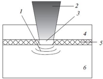
The LSP technology is applied via the propagation of high amplitude shock waves in materials (more than 1 GPa) formed by short laser pulses (about 1-50 ns) with a high power density (as a rule, more than 1 GW/сm2). Usually the process is carried out under the “constrained” environment (Fig. 1). The studied metal surface is covered by an opaque layer, and then it is placed in a transparent medium, which is a dielectric material transparent to the laser beam (as a rule, water). The opaque coating serves to exclude thermal effects in the material. This thin layer evaporates during absorption of the laser energy. The transparent layer restricts the travel of the expanding steam and plasma from the material surface, thereby generating higher pressure (as compared to the situation without such a layer) with an amplitude of up to 3 GPa. The studied material is subjected to quite a high deformation level within a very short time (less than 10-6 s), which results in quick plastic deformation and formation of “useful” compressive residual stresses, which contributed to the improved mechanical characteristics of the material [5].
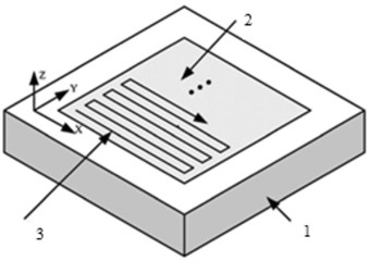
Since the processing area of one laser spot is very small, the practical result after using the LSP technology is obtained after processing with the large number of exposures applied by sequential scanning of the processed surface in both directions (Fig. 2(a)).
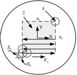
In this article, the central part of the sample of 15×15 mm was subjected to the LSP procedure (Fig. 2(b)). The studied material is the titanium alloy Ti-6Al-4V alloy. For qualitative evaluation and control of the laser pulse distribution on the processed surface, we introduce the concept of the overlapping level, designate it as , and deter- mine it as follows:
where is the laser spot radius and is length of coincidence (overlap) of two consequent laser spots (for the case shown in the Fig. 2(b), , and correspondingly, 50 %).
Fig. 1Basic diagram of LSP technology: 1 – shock wave, 2 – laser pulse, 3 – plasma, 4 – transparent layer, 5 – opaque layer, 6 – studied material

The laser spot overlap procedure is achieved by the digital control of two parameters: the rate of continuous scanning toward and pitch interval toward . The laser pulses (every pitch) were shifted along the direction after passing the required distance towards . The control parameters are easily determined if the overlapping levels and in both directions are known:
where is the laser pulse repetition frequency, () is the distance between two consecutive laser spots, and () are conditional numbers of laser spots in both directions required for identification of each pulse with computer control. Here, the general scheme for scanning control for the LSP procedure is described. In these studies, the overlapping levels along axes and were equal.
Fig. 2Scheme of scanning trajectory of surface processed by laser beam in order to study effect of laser spot overlap: а) general scheme, where 1 is studied sample, 2 is processed area of LSP action, 3 is scanning trajectory; b) is definition of term “overlapping level,” where 4 is laser spot

a)

b)
3. Parameters of laser action
A neodymium YAG laser with Q-switching, a repetition frequency of = 10 Hz, a temporary profile with a Gaussian distribution is the source of laser radiation in compared experiments [6]. Table 1 shows the parameters of laser radiation for the LSP procedure. The data for the finite element simulation were selected accordingly.
Table 1Parameters of laser radiation for the LSP procedure
Wavelength nm | Pulse duration ns | Pulse energy J | Diameter of laser spot mm | Overlapping levels % |
1064 | 15 | 8 | 1 | 50, 70, 90 |
4. Problem solving technique
Finite element realization of the LSP technology should have the two parts. Dynamic analysis is carried out at the first stage with the help of LS-DYNA (license number 10312012) in an explicit form; as a result, we obtain the form distribution of the shock wave over time and the dynamic response of the material [7]. When the dynamic state is stabilized, the obtained stress will be imported to the ANSYS implicit solver (license number 660578) for static analysis and to obtain the residual stresses distribution and surface deformation.
5. Material constitutive relation
Target material was assumed to be an elastic–plastic homogeneous isotropic material, and its initial stress was assumed to be 0 MPa. In LSP, material strain rate is very high and reaches up to 106 s-1, so the constitutive relation obtained from quasi static conditions is no longer valid. The Johnson Cook (J-C) model takes into account the strain hardening, the strain rate effects and thermal effects on the flow stress in material, which has been widely applied to simulate the material response to high strain rate and large strain. It is expressed as follows [8]:
where and represents the equivalent stress and plastic strain, – dimensionless equivalent strain rate, is the yield stress at the reference strain rate ( = 1,0 s-1). and exponent represent the strain hardening effect; stands for the strain rate hardening effect. is homologous temperature, which is given by:
where and stand for the melting point of material and room temperature respectively. In the case of LSP, the ablative layer was sacrificed to protect the target from laser irradiation, so the target could be shielded from laser thermal effects. Therefore, the temperature effect in the J-C model could be neglected.
Eq. (5) contains five material constants which are determined empirically: is the statistical yield point, is the strain hardening modulus, is the strain hardening coefficient, is the deformation rate coefficient, and m is the thermal softening coefficient. The Johnson-Cook model anticipates independence of the relative influence of strain hardening, the rate of plastic deformation, and increase in temperature for all rates and temperatures of plastic deformation In Eq. (1), the formula in the first parenthesis determines the strain as a function of deformation for = 1 and = 0; in the second and third parenthesis, it determines the influence of the instantaneous rate of deformation and temperature on the yield point, respectively. Since the LSWP technology pertains to nonthermal technologies, thermal effects are ignored, and during simulation, we use the simplified Johnson-Cook model:
During these studies, calculations were carried out and compared with the experiments for the titanium alloy Ti-6Al-4V. Its mechanical characteristics are given in Table 2.
Table 2Mechanical characteristics of Ti-6Al-4V titanium alloys
Characteristics, dimensions | Value |
Density , kg/m3 | 4500 |
Poisson ratio | 0.342 |
Elasticity modulus , GPa | 110 |
Hugoniot yield point, GPa | 2.8 |
, MPa | 1098 |
, MPa | 1092 |
0.93 | |
0.014 |
6. Simulation of surface stressing by a shock wave
For the LSP technology, the loading for every pulse is simulated by the application of a laser pulse of surface loading equal the shock wave pressure to the finite elements. According to [3], if the shock wave profile has a Gaussian curve, the spatially heterogeneous pressure at distance from the center of the laser spot will be:
where is the laser spot radius.
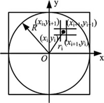
The time interval between each two subsequent actions was selected as quite large in order to guarantee completion of the plastic deformation process before the next pulse. Let us assume that the origin of the local coordinate system is at the center of the laser spot (Fig. 3). Let us specify the coordinates of the middlemost unit of the stressed -th finite element as (, ). Then the radial distance from the center of the laser spot to the -th element will be:
Fig. 3Scheme for calculating radial distance for each element

7. Results and discussion
Figure 4(a) shows the distribution of residual stresses inward the material along axis at different overlapping levels. The results of finite element simulation (FES) and known experimental studies are presented [4]. The studied material before the LSP technology has almost zero initial residual stresses (Fig. 4(a)). Thus, it is possible to neglect the half-studied effect: the influence of the initial residual stresses on the propagation of shock waves in a material.
The results show that the region of important plastic deformations inward the material is only about 200 μm. This region is considerably less compared to the traditional LSP technology (with a large laser spot radius of about 1 cm or more); it is the result of the small laser spot during investigations.
Fig. 4distribution of residual stresses on the surface (x) and inward (z) of the material: a) 1 prior to LSP, 2 is experiment (from [4]) at η = 50 %, 3 is FES at η = 50 %, 4 is experiment at η = 90 %; 5 is FES at η = 90 %; b) 1 η = 50 %, 2 η = 70 %, 3 η = 90 %
![distribution of residual stresses on the surface (x) and inward (z) of the material: a) 1 prior to LSP, 2 is experiment (from [4]) at η = 50 %, 3 is FES at η = 50 %, 4 is experiment at η = 90 %; 5 is FES at η = 90 %; b) 1 η = 50 %, 2 η = 70 %, 3 η = 90 %](https://static-01.extrica.com/articles/17638/17638-img5.jpg)
a)
![distribution of residual stresses on the surface (x) and inward (z) of the material: a) 1 prior to LSP, 2 is experiment (from [4]) at η = 50 %, 3 is FES at η = 50 %, 4 is experiment at η = 90 %; 5 is FES at η = 90 %; b) 1 η = 50 %, 2 η = 70 %, 3 η = 90 %](https://static-01.extrica.com/articles/17638/17638-img6.jpg)
b)
It is known that in the case of small laser spots, a shock wave propagates with a spherical profile and attenuates quickly compared to a flat shock wave in the case of large spots [1]. Therefore, the spherical shock wave appeared in case of small laser spots penetrate into metal at a short distance and therefore the plastic deformation region is less.
Residual stresses obtained numerically and experimentally for two values of the overlapping level = 50 % and 70 % were compared. The results of the experiments showed that compressive residual stresses increase with increasing depth at a short distance, reach the maximum level, and then decrease. However, the results of finite element simulation showed that residual stresses are maximum near the surface and they gradually decrease as penetration increases. It seems that it is necessary to explain this phenomenon by the assumption that the opaque protective coating used during experiments cannot completely isolate the studied material from the influence of temperature, although this layer guarantees its integrity and protection from melting and evaporation. This assumption requires additional empirical support.
It is known [2-4] that the temperature effect considered in this finite element model should initiate tensile residual stresses with their prompt disappearance when laser radiation stops. Thus, the compressive residual stresses created by the pure mechanical LSP effect should be negligibly reduced by tensile residual stresses. Therefore, this model could not specify stresses at higher overlapping levels ( = 90 % or higher), since in this case, the temperature effect is strong (Fig. 4(a)) and not negligible. The temperature effect was considered in [4] but without regard for the opaque layer. Simulation by the LSP technology with acceptable accuracy and with due account for the temperature effect is not a problem of the immediate future.
Fig. 4(b) shows the simulated residual stresses along axis on the free surface at different overlapping levels. The results show a regularity when residual stresses increase with increasing overlapping level, but they remain more homogeneous.
Finite element simulation of the LSP technology with a low laser output energy using the laser spot overlap effect is done for the titanium alloy Ti-6Al-4V. The total finite element model of the laser spot overlap effect was realized, and residual stresses in the surface regions at different overlapping levels were obtained.
The results of distribution of compressive residual stresses on the surface and inward the material correlate well with the known experimental data. It is found that for the increase in the overlapping level, residual stresses increase; as well, they become more homogeneous.
References
-
Peyre P., Scherpereel X., Berthe L., Fabbro R. Current trends in laser shock processing. Surface Engineering, Vol. 14, 1998, p. 377-380.
-
Zhang Y. K., Lu J. Z., Ren X. D., Yao H. B., Yao H. X. Effect of laser shock processing on the mechanical properties and fatigue lives of the turbojet engine blades manufactured by LY2 Al alloy. Materials and Design, Vol. 30, Issue 5, 2009, p. 1697-1703.
-
Ocana J. L., Morales M., Porro J. A., Dнaz M., Ruiz de Lara L., Correa C., et al. Induction of Thermos-Mechanical Residual Stresses in Metallic Materials by Laser Shock Processing. Encyclopedia of Thermal Stresses, 2014, p. 2427-2444.
-
Hu Yongxiang, Yao Zhenqiang Numerical simulation and experimentation of overlapping laser shock processing with symmetry cell. International Journal of Machine Tools and Manufacture, Vol. 48, 2008, p. 152-162.
-
Sakhvadze G. Zh., Gavrilina L. V. Single and multiple laser shock processing of materials. Journal of Machinery Manufacture and Reliability, Vol. 6, 2015, p. 75-80.
-
Sakhvadze G. Zh., Gavrilina L. V., Kikvidze O. G. Influence of laser spot overlap effect on residual stresses during laser-shock-wave processing of materials. Journal of Machinery Manufacture and Reliability, Vol. 3, 2016, p. 258-265.
-
Sakhvadze G. J. Laser shock processing of materials to produce nanostructures. Special Issue of Scientific Journal of IFToMM “Problems of Mechanics”, Vol. 2, Issue 55, 2014, p. 68-73.
-
Johnson G. R., Cook W. H. A constitutive model and data for metals subjected to large strains, high strain rates and high temperatures. Proceedings of the 7-th International Symposium on Ballistics, The Hague, 1983, p. 541-547.
About this article
The work is financially supported by the Ministry of Education and Sciences of the Russian Federation within the Federal Target Program “Studies and Developments of Promising Trends in Russia’s Science and Technology Sector for 2014-2020”. Subsidy Agreement No. 14.607.21.0040 of July 22, 2014, Project RFMEFI60714X0040.
