Abstract
The incompatibility of inherent physical properties of the individual constituents often leads to the failures of the whole multi-phase system during the service. We need to investigate the residual stress caused by different inherent properties of the constituents that could finally cause the failure of the whole system and predict the severe time. This paper synthesized a special network-structure composite as the investigated system. The hybrid composites have a honey-comb structure with the high thermal conductivity HfB2 encapsuling the low thermal conductivity B4C. Although the overall thermal conductivity is greatly improved, the different thermal expansivity of the composites can result in a severe residual stress within the composite, which will finally evolve into macroscopy cracks and becomes a threat to the normal operation of the whole system. It is therefore necessary to investigate the magnitude of residual stress and its corresponding distribution. We employed the real-situation modeling and finite element analysis to probe the residual stress caused by the incompatibility of thermal expansivity. This method is effective and has its practical value when applying in relevant industries applications for the prediction and preventing the possible accidents.
1. Introduction
Multi-phase systems composed of different materials with various thermal and mechanical properties are important in our daily life. Due to the high density of interfaces and the outstanding hybrid structure, the functionality and mechanical behavior of the multi-phase systems are superior than their single-phase counterparts, such as high strength, comprehensive high thermal conductivity, etc. Therefore, they are also widely used in special conditions. Taken high strength low alloy steels as an example, they have been widely used for architectural constructions, offshore platforms, and energy industry due to their high strength, high toughness, good weld ability [1]. There are also applications in extreme conditions. For example, under irradiation environment in nuclear reactors, properties of structural materials are often degraded due to the irradiation induced embrittlement, especially the helium induced embrittlement [2]. Multilayer composites made of a hierarchically layered structure is more resistive to the formation of large helium clusters, which makes it to be a more irradiation resistant material, and a promising candidate material for the future application of nuclear energy [3, 4].
However, due to the different thermal conductive behavior and mechanical properties of individual components, the heat distribution and residual stress in the multi-phase systems are unclear. These issues are of critical importance for the long-term and safe operation of the multiphase systems during the service. Although the comprehensive properties are greatly improved, different thermal conductivity of the components and aggregation of residual stress in the multi-phase components are great threats to the normal operation of whole systems. Therefore, to unveil the thermal conductive and distribution of residual stress in the multi-phase systems is meaningful.
In this study, we take B4C-HfB2 composite as our model system. The reason why we take it as our investigated system is that B4C owns high hardness and a low thermal conductivity, while HfB2 has superior thermal conductivity and a relative low hardness [5-7]. The thermal expansivity of B4C and HfB2 are 20×10-6/K [8] and 6.39×10⁻⁶/K [9], respectively. This shows a high discrepancy of the thermal expansivities. Then, we employed a series of novel methods to synthesize a special honey-comb structure with the HfB2 encapsuling low B4C. The combination of the B4C and HfB2 results in a great improvement of the thermal conductivity and its mechanical properties. By modeling the hybrid-structure system based on the microstructure of B4C-HfB2 recorded by SEM, we used finite element analysis to investigate the detail thermal conductivity of the B4C-HfB2 system and the results turned to be well consistent with the experimental results. This proves that our method is rigid and correct. By applying the same model and method, we unveil the internal stress caused by the incompatibility of thermal expansivity of the individual component, which is hard to be detected by experiment, however, it is important to predict the possible accidents caused by the failures of the components.
2. Experimental procedures
In order to get the special honey-comb hybrid structure of B4C-HfB2 composite to be investigated, we sequentially applied molten-salt method and spark plasma sintering (SPS) method, details of the synthesis process are described as follows.
2.1. Powder preparation, XRD characterization and SEM analysis
Pure B4C powder and the mixed B4C and Hf powder with the molar ratio of 4:1 and 6:1 were chosen as the raw materials, respectively. NaCl and KCl with the molar ratio of 1:1 was mixed with the raw materials with the same mass. After mixing the powders uniformly in a Al2O3crucible. The crucibles containing the mixing powder were heated in a 1200℃ and argon atmosphere to make the raw materials react with each other by the following equation in the molten salt.
B4C+Hf → C+HfB2
After the in-situ reaction, the cooled-down molten salt bulk containing the reacted powder were washed by deionized water to remove the residual salt and the as-reacted C. The powders were finally dried to remove the residual water before a series of the following microstructural characterization.
In order to get the phase composite of reacted powder, we performed the XRD analysis on the dry powder. The result is shown below.
Fig. 1XRD patterns of molten-salt reaction
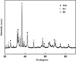
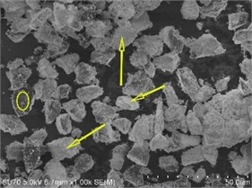
Fig. 2SEM image of molten salt reaction
The compositions of the products are identified in the Fig. 1. It indicates that the pure products contain Hf, B4C and HfB2. Among those elements and compounds, traces of Hf can be found, which is excessive in the first step of the reaction.
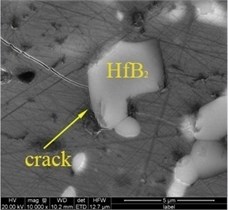
To get the microstructural morphology of the reacted powders, we employed the SEM analysis to record the detail microstructural feature of the reacted powders. The microstructural feature of the as-reacted powder of B4C and HfB2 is shown in Fig. 2. It can be clearly seen that the HfB2 (white contrast) covered the B4C (dark contrast), as labeled by the yellow arrows. However, as indicated by the XRD results, there still existed regions without the HfB2, this region was indicated by the yellow circles.
2.2. Spark Plasma Sintering, XRD Characterization and SEM analysis
To get the bulk material, we employed SPS technique. The SPS process was performed at a temperature of 2000 ℃ and a vacuum state of 100 Pa. After the temperature cools down to room temperature, the bulk has a 98 % density of the theoretic density. In order to characterize the microstructure of the bulk, we performed the XRD and SEM on the as-received bulk, results are shown in the following sections.
Based on the XRD pattern shown in Fig. 3. The bulk material synthesized by SPS processing contains only B4C and HfB2. Compared to the Fig. 1, the disappearance of Hf proves that Hf has been fully reacted with B4C and results in HfB2 phase.
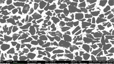
SEM was used to probe the detail microstructural feature of the bulk material. Fig. 4 presents a clear hybrid microstructure, of which, the white contrast is HfB2, and the dark contrast is B4C. From a two-dimensional view point shown in the SEM image, the B4C and HfB2 make up a typical network microstructure, which proves that the from the three-dimensional point of view, the B4C were encapsuled by HfB2, and results in a honey-comb structure.
Fig. 3XRD pattern by SPS processing
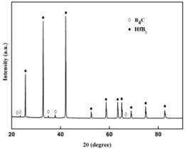
Fig. 4SEM image of the B4C-HfB2 bulk composites
2.3. Thermal properties and the crack propagation behavior
From the Fig. 5, it can be observed that with higher ratio of HfB2, the thermal conductivity of composition increases under each temperature condition, which illustrates that the hybrid structure greatly enhances thermal conductivity of the composition. Fig. 6 shows a typical crack propagating behavior in the B4C-HfB2 composite, the crack is clearly observed to propagate along the HfB2 surface when it encounters the HfB2particle.
Fig. 5Thermal conductivity ofB4C-HfB2
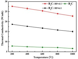
Fig. 6Crack propagation in the B4C-HfB2 composite
2.4. Experimental setup
To create a multi-phase system as the typical model to study. We design a special honey-comb structure with a high thermal conductivity HfB2 and a low thermal conductivity B4C materials. The novel molten-salt method was successfully adopted to synthesize the pre-requisite powders. Subsequent SPS was used to synthesize the bulk composites. The composition and microstructural feature of the bulk composites were characterized by employing the XRD and SEM techniques. It clearly revealed that the final bulk material is made up of B4C and HfB2phases, and the special-designed structure was also achieved. This provides us a good model system to be investigated. The thermal conductivity of B4C-HfB2 composite increases with the increasing of HfB2content, and the crack propagates in an interesting way, which is related with the residual internal stress, and will be investigated below.
3. Numerical analysis
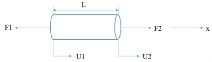
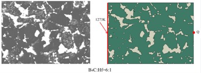
To evaluate the effect of the HfB2 phase on the heat transfer performance and the mechanical properties in the B4C-HfB2 composite, finite element analysis was performed based on a 2-D finite-element model established on the typical microstructure of the SEM images. The geometric construction of the B4C-HfB2 composite FE model was established by the CAD contouring of the SEM images showed in Fig. 7. Here we need to set the thermal and mechanical boundary conditions at the same time. In thermal boundary conditions, an initial temperature of 773K was assigned to the entire geometric area to simulate the actual environment temperature, and the 1273K was assigned to the left edge of the geometric model to as a stable heater source, the other edges were assigned adiabatic boundary conditions. In order to simulate the phenomenon of free expansion during the heating process, the left end of the geometric model is constrained to move along the x direction, and the upper left end of the model is set as a fixed constraint in mechanical boundary conditions. The geometric models and corresponding boundary conditions for all components are shown in Fig. 7.
Fig. 7Model illustration of stress experienced by one dimensional elastic rod
3.1. Hanics analysis
For mechanical analysis of composite materials, we must first establish a balance equation. Establish geometric deformation equation, the strain of the rod element that subjected to an external force can be expressed as , where is the amount of deformation along the axial direction ( axis), is the original length of the element. The physical equations of the element can be established by stress and strain , where is defined as elastic modulus of the material, which is equivalent to the stiffness coefficient in the FE analysis, and it can be expressed by stiffness matrix in FE simulation . The formula can be written in matrix form and simplified:
where [] is Element stiffness matrix, is load matrix, is displacement vector.
In the finite element calculation, the displacement is used as the basic variable, when the displacement of each node calculated, the strain can be obtained through the relationship between the displacement and strain. Finally, the stress can be obtained through the physical equation.
3.2. Thermal analysis
Considering the heat transfer analysis, the temperature gradient is . Heat flux , where is the heat flux rate and is the density of heat flux. According to Fourier’s law: the heat flux is directly proportional to the temperature gradient and in the opposite direction . The formula can derive , where is the thermal conductivity. Density of heat flux can also be expressed in . According to the above analysis, the Fourier heat conduction equation can be obtained:
According to the laws of thermodynamics, thermodynamic equilibrium equations can be established , where , and are the heat obtained by the object from the outside, the heat generated by the internal heat source and the energy required by the object to raise the temperature respectively. According, the Green’s formula, We can conclude:
After simplification, the heat conduction equation can be obtained .
According to the types of boundary conditions for thermodynamic problems, the calculation of thermal structure coupling can be realized through finite element analysis.
3.3. Thermal properties
To predict the heat transformation behavior and the thermal properties of the composites. We established two-dimensional models, which were based on the real-structural SEM images of the composites, as shown in the Fig. 8. A series of the following analysis were established on the above models.
Fig. 8SEM images of B4C-HfB2 composites and the corresponding models
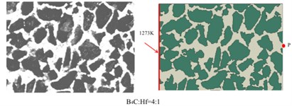
Based on the above models and the formulas in the analysis section, we got the temperature distribution as a function of time in B4C-HfB2 composites with molar ratio of B4C/Hf = 4:1, 6:1 and pure B4C, respectively, as shown in Fig. 9. As it can be seen that within the same time duration, the temperature is higher at a certain distance from the left side of the boundaries, which were set to be 1270 K and as the initial boundary condition. It proves that heat transfers faster in the composites with higher HfB2 concentration, i.e. the HfB2 phase improves the overall thermal conductivity of the composites.
To have a comparison between the different composites quantitatively, we measured the temperature of middle points on the right boundaries of each composites, i.e., P, Q and S, respectively. The positions were shown in Fig. 8. The temperature of P, Q and S points as a function of time is shown in Fig. 10. It demonstrates in a quantitative way that higher molar ratio of HfB2 helps improve the thermal conductivity of composites. This is well consistent with the results obtained by experimental measurement as indicated in Fig. 5.
Fig. 9Temperature distribution in B4C-HfB2
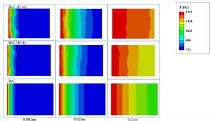
Fig. 10Temperature of the right-hand boundary

3.4. Internal stress distribution
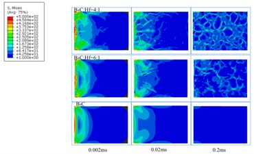
We set the boundary condition of 500 N on the left-hand side, and based on the models established on the SEM images and the above-mentioned methods, we got a quantitative distribution of internal stress in three samples as shown in Fig. 11. It can be clearly seen that the most of the internal stress was distributed along the interface between the boundaries of B4C and HfB2. It is also indirectly proved by the crack propagation along the boundaries between B4C and HfB2, as indicated by Fig. 6. Therefore, the more the boundaries of the composites, the more residual stress, which is obviously not benefit for the improvement of mechanical properties. In contrast, in pure bulk B4C, almost no internal stress was found. The internal stress is hard to be detected by experimental method, which proves the importance of our methods.
Fig. 11Internal stress distribution in the B4C-HfB2 composites with different B4C/HfB2 molar ratios
4. Conclusions
In this study, we fabricated a special honey-comb bulk composites with the high thermal conductivity HfB2 encapsuling the low thermal conductivity B4C. Finite element analysis was employed to investigate the thermal transport behavior of the composites, it is consistent with experiment results, and proves the feasibility of our analysis process. The same model was used to predict the residual internal stress of the multi-phase system, and shows the magnitude and distribution of residual stress, which is important for the prediction of the possible failure of the system that cannot be obtained by experimental methods. Our study provides a new method to probe the internal stress caused by the discrepancy of physical properties of individual components, which can be used to predict the possible failure of components, and the normal operation life time of the whole system. The method in this paper provides a new insight to investigate the possible threat to safety of the system that lies in the individual components. Hence, this method can provide us an approach to predict the potential threat of the whole system.
References
-
X. J. Sun, S. F. Yuan, Z. J. Xie, L. L. Dong, C. J. Shang, and R. D. K. Misra, “Microstructure-property relationship in a high strength-high toughness combination ultra-heavy gauge offshore plate steel: The significance of multiphase microstructure,” Materials Science and Engineering: A, Vol. 689, pp. 212–219, Mar. 2017, https://doi.org/10.1016/j.msea.2017.02.058
-
H. Trinkaus and B. N. Singh, “Helium accumulation in metals during irradiation – where do we stand?,” Journal of Nuclear Materials, Vol. 323, No. 2-3, pp. 229–242, Dec. 2003, https://doi.org/10.1016/j.jnucmat.2003.09.001
-
R. Gao et al., “Superconducting Cu/Nb nanolaminate by coded accumulative roll bonding and its helium damage characteristics,” Acta Materialia, Vol. 197, pp. 212–223, Sep. 2020, https://doi.org/10.1016/j.actamat.2020.07.031
-
M. Wang, I. J. Beyerlein, J. Zhang, and W.-Z. Han, “Defect-interface interactions in irradiated Cu/Ag nanocomposites,” Acta Materialia, Vol. 160, pp. 211–223, Nov. 2018, https://doi.org/10.1016/j.actamat.2018.09.003
-
T. Maruyama, S. Onose, T. Kaito, and H. Horiuchi, “Effect of fast neutron irradiation on the properties of boron carbide pellet,” Journal of Nuclear Science and Technology, Vol. 34, No. 10, pp. 1006–1014, Oct. 1997, https://doi.org/10.1080/18811248.1997.9733777
-
L. Bsenko and T. Lundström, “The high-temperature hardness of ZrB2 and HfB2,” Journal of the Less Common Metals, Vol. 34, No. 2, pp. 273–278, Feb. 1974, https://doi.org/10.1016/0022-5088(74)90169-6
-
K. Sairam, J. K. Sonber, T. S. R. C. Murthy, C. Subramanian, R. C. Hubli, and A. K. Suri, “Development of B4C-HfB2 composites by reaction hot pressing,” International Journal of Refractory Metals and Hard Materials, Vol. 35, pp. 32–40, Nov. 2012, https://doi.org/10.1016/j.ijrmhm.2012.03.004
-
G. V. Tsagareishvili et al., “Thermal expansion of boron and boron carbide,” Journal of the Less Common Metals, Vol. 117, No. 1-2, pp. 159–161, Mar. 1986, https://doi.org/10.1016/0022-5088(86)90025-1
-
J. Castaing and P. Costa, “Properties and uses of diborides,” in Boron and Refractory Borides, Berlin, Heidelberg: Springer Berlin Heidelberg, 1977, pp. 390–412, https://doi.org/10.1007/978-3-642-66620-9_22
About this article

