Abstract
This study conducts an analytical investigation of the dynamic response characteristics of a two-stage series composite system (TsSCS) with a planetary transmission consisting of dual-power branches. An improved incremental harmonic balance (IHB) method, based on the arc length extension technique, is proposed. The results are compared with those of the numerical integration method to verify the feasibility and effectiveness of the improved method. Following that, the multi-scale perturbation (MsP) method is applied to the TsSCS proposed in this paper. The frequency response equations of the primary resonance, subharmonic resonance, and superharmonic resonance are solved to generate the frequency response characteristic curves of the planetary transmission system in this method. A comparison between the results obtained by the MsP method and the numerical integration method proves that the former is ideal and credible in most regions. Considering the parameters of TsSCS excitation frequency and damping, the nonlinear response characteristics of steady-state motion are mutually converted. The effects of the time-varying parameters and the nonlinear deenthing caused by the gear teeth clearance on the amplitude-frequency characteristics of TsSCS components are studied in this special topic.
Highlights
- The dynamic response characteristics of a two-stage series composite system with a planetary transmission system that consists of dual-power branches are analyzed.
- An alternative to the computationally heavy and financially expensive numerical methods to analyze planetary transmission systems is proposed.
- A comparison between the results by the MsP method and the numerical integration method proves that the former is ideal and credible in most regions are obtained.
- The parameters of TsSCS excitation frequency and damping, the nonlinear response characteristics of steady-state motion are mutually converted.
- The effects of the time-varying parameters and the nonlinear deenthing caused by the gear teeth clearance on the amplitude-frequency characteristics of TsSCS components are studied.
1. Introduction
Planetary gears are the most critical underwater components of ships that transfer real-time power and time-varying motion. Owing to its compact transmission structure, strong anti-scuffing bearing performance, and high transmission precision, the planetary gear transmission is widely used in various mechanical systems. The application of the planetary transmission system in the underwater military industry has created an urgent demand for lightweight and reliable structures [1]. Planetary gears have various dynamic response properties due to their complex inherent characteristics [2]. The dynamic behavior analysis of the alternating meshing process is a popular area of study in the design and applications of various planetary gear mechanisms and their transmission systems [3-5]. Many researchers have been working on new simulation analysis methods to gain an in-depth understanding of the dynamic meshing transients of planetary gears [6-8]. Numerous studies have been performed on the dynamic behavior analysis method, which plays an important role in determining the performance of planetary gears. In addition, the machinery industry is paying more attention to the dynamic characteristics of planetary gear drives and the resulting vibrations and noise [9-11].
A two-stage series composite system (TsSCS), consisting of a planetary transmission system with dual-power branches, is a complex and flexible mechanical system that comprises several parts [12]. A TsSCS is generally divided into two parts: the transmission system (gear train, transmission shaft, and bearing) and the structural system (gearbox, dual-branch composite planetary gearbox, dynamometer, and bracket) [13]. The increasing number of studies on the vibrations and noise produced by underwater devices, particularly on controlling the noise produced by the power rear transmission system of underwater devices, must account for the TsSCS and its meshing process, in addition to the real-time dynamic meshing force acting on the system. Fig. 1 reveals outline drawing and cutaway view of a certain type of warship TsSCS.
Fig. 1Outline drawing and cutaway view of a certain type of TsSCS
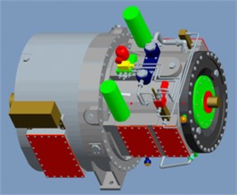
a) Outline drawing of a certain type of TsSCS
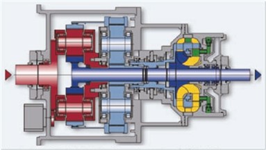
b) Cutaway view of a certain type of TsSCS
Few theoretical studies consider the TsSCS with a planetary transmission consisting of dual-power branches as a subject [14]. It is important to possess some professional design knowledge while studying the unique kinematics and geometric characteristics of a TsSCS consisting of a planetary transmission with dual-power branches [15]. The TsSCS, with a dual-power branch planetary transmission, is preferred to the horizontal shaft gear deceleration system, especially in applications requiring high linear speed power density designs and kinematic flexibility to optimize different speed ratios [16-18]. It has been demonstrated that reducing the spoke thickness to increase gear flexibility also resolves several internal gear and planetary frame errors and operational errors, in addition to making the system lighter [19]. Moreover, a flexible internal gear improves the load sharing between planets, which is an important feature if manufacturing and assembly related gear and carrier errors are inevitable. Thus, it is difficult to quantify the factors that influence the TsSCS with a dual-power branch planetary transmission under quasi-static conditions. The research in this subject is TsSCS with a planetary transmission consisting of dual-power branches, which uses a translation-torsion coupling model. It is difficult to solve the problem of dynamic differential equations by applying existing analytical methods. To deeply study the dynamic characteristics of TsSCS, it is necessary to find a suitable new method to solve this kind of complex model. This article mainly studies the analytical solution method of TsSCS kinetic equation. The translation-torsion coupling dynamic equation of TsSCS with a planetary transmission consisting of dual-power branches is non-dimensionalized.
Modals are the inherent characteristics of gear transmission systems [20-22]. A modal analysis is used to determine the vibration characteristics of the designed structure or its transmission components. The modal analysis is a part of the structural dynamics analysis and is also the starting point for the subsequent transient dynamics, harmonic response, and spectrum analyses [23]. Each mode has a corresponding natural frequency, damping ratio, and mode shape [24]. A modal analysis is a modern technique that is used to study the dynamic characteristics of a transmission system structure, including modal analysis of linear vibration theory and experimental modal analysis [25]. An experimental modal analysis can only be carried out after the components of the structure have been processed and assembled. However, it has a longer test cycle and is more expensive. In addition, it is easily affected by the quality of the processing and assembly steps. Thus, it is difficult to use these results in the design analysis stage [26]. As a result, the experimental analysis is used to verify the results of the analysis of the theoretical model and modify it accordingly. Various modal parameters, such as the modal frequency, shape, quality, stiffness, damping, etc., affect the dynamic load design.
Since most of the internal, planetary, and sun gears are excluded from these models, it is not possible to study the effect of the internal gear thickness on the performance of the TsSCS and its effect on the stress acting on the planetary and sun gears and the load sharing between the planets. Similarly, it is not possible to accurately predict the shape and deflection of the gears. Although the above mentioned studies indicate that the adverse effects of the gear and planet carrier manufacturing errors can be minimized by improving the planetary load-sharing characteristics under quasi-static conditions, these modifications lead to increased gear contact stress. These static analyses alone cannot predict the actual design of the system because the increasing flexibility of the TsSCS causes its performance to change only under dynamic conditions. This might also lead to an rise in the stress acting on the gear. The current study, thus, studies the inherent characteristics of the TsSCS, constructs its dynamic model, and synthetically analyzes its inherent and dynamic response characteristics.
2. Mathematical model of the modal analysis
The first step of the dynamic calculation is to determine the natural frequency and mode shape of the structure while ignoring its damping. These results reflect the basic dynamic characteristics of the structure and its response trend under dynamic loads. The double-branch compound transmission system test bench is considered to be a single elastic body. The differential equation of motion describing the overall vibration of the test bench is given as:
where , , and refer to the acceleration, velocity, and displacement vectors of the nodes in the vibration system, respectively. , , and represent the mass, damping, and stiffness matrices of the vibration system, respectively. represents the external force vector received by node. Only the inherent characteristics of the vibration system are modeled and solved in the modal analysis. The model does not contain external force terms and neglects the damping terms that are assumed to have an insignificant impact on the system. The differential equation of motion for an undamped free vibration system is given as:
The resonance solution form of the equation is given as:
where is the displacement vector and is the characteristic vector that amplitude of the displacement vector. is the natural angular frequency.
The resonance form of the equation is a key to the numerical solution. It is derived under the assumption that all degrees of freedom of the vibrating structure move in a synchronous manner. During this process, the basic shape of the structure does not change, only the amplitude varies.
2.1. Dimensionless differential equation of the second-stage star gear train
(1) Dimensionless differential equation of the ring gear of the star gear train:
(2) Dimensionless differential equation of the sun gear of the star gear train:
(3) Dimensionless differential equation of the star gear of the star gear train:
On the basis of the non-dimensionalized equation, the incremental harmonic balance method and the multi-scale perturbation analysis method based on the arc-length continuation technology are respectively used to obtain It is suitable for the solution of TsSCS kinetic equation.
2.2. Dimensionless differential equation of the second-stage planetary gear train
(1) Dimensionless differential equation of the planet carrier of the planetary gear train:
(2) Dimensionless differential equation of the sun gear of the planetary gear train:
(3) Dimensionless differential equation of the planetary gear of the planetary gear train:
Rewriting Eq. (9) in its matrix form:
It is noteworthy that the stiffness matrix is no longer symmetric due to the transient nature of the phase angle of the planetary gears.
3. Incremental harmonic balance and arc length extension method
The harmonic balance method uses a description function to approximate the nonlinearity caused by the gap and is widely used in planetary transmission systems. The excitation and response parameters are assumed to be harmonic functions and are substituted in the nonlinear equation. The approximate expressions of the response and phase parameters can thus be obtained by using the condition of equal power coefficients. Since this method is not limited by the degree of nonlinearity, all the frequency response values can be obtained. However, owing to the limitations of the assumed excitation and response form, the accuracy of this method is not satisfactory, particularly if the first harmonic is considered. It results in the artificial loss of the superharmonic, subharmonic, or chaotic responses. Lau and Cheung proposed the incremental harmonic balance (IHB) method in 1981 to improve the accuracy of the existing harmonic balance method. A Taylor series expansion was performed on the nonlinear differential equations while ignoring the higher-order derivatives to obtain the differential equations in an incremental form. The Fourier series and the Galerkin method were then used to obtain nonlinear algebraic equations. The entire process is divided into an incremental component (Newton-Raphson method) and a harmonic balance component (Galerkin method). This method has the advantage of free control algorithm convergence accuracy, among many others, and is thus an effective method for solving complex nonlinear problems [27]. Rohan and Lukeš used the incremental harmonic balance method for a two-stage star gear train with multiple degrees of freedom; however, it is only used the response as an incremental parameter [28]. If a singular point is encountered along the path of the solution branch, the quasi-arc length parameter is introduced. The original variables and parameters are assumed to be functions of the arc length. This condition is added to the original equation to smoothly track the path through the singular point [29]. The harmonic balance method, based on the continuation of the arc-length, has been applied to the pure torsion model of a fixed shaft and a single-stage planetary transmission [30]. The incremental harmonic balance method, based on the continuation of the arc length, is used to calculate the dynamic characteristic equation of the system used in this study. The two incremental parameters (response and fundamental frequency) are expressed in terms of the arc length to smoothly overcome the singular points along the path. The formula to calculate the steady-state response of a two-stage herringbone planetary transmission system is presented in this study. This method has not yet been applied to planetary gear transmission systems.
3.1. Incremental harmonic balance method
A new time variable is introduced in this method. The expression of , initially written in terms of , is rewritten in terms of . As a result, Eq. (10) is written as:
The incremental process is the first component of the IHB method. If and are the solutions of Eq. (11), their neighboring points can be expressed as:
where and are the incremental parameters.
By substituting Eq. (12) into Eq. (11) and omitting high-order small quantities, the incremental equation matrix can be obtained with and as the unknown quantities:
where is the unbalanced force vector (also referred to as the residual correction term in some studies). If and are exact solutions, then .
The second component of the IHB method involves the harmonic balance process. The steady-state response of the system is described by a Fourier series. The response contains only odd harmonics and is given as follows:
The response of the system and its increment can be written in the following matrix form:
After substituting Eq. (17) into the incremental Eq. (13) and the unbalanced force Eq. (14), the Galerkin averaging process is applied to obtain the equations for the unknown quantities and :
where:
3.2. Arc length extension method
The arc length parameter equation, corresponding to Eq. (11), can be expressed as:
Assuming and and substituting the increments of , , and in Eq. (19), the increment equation can be obtained, as shown below:
Fig. 2 shows a part of the analytical balance path of the arc-length extension method.
Eq. (19) can be rewritten as:
The initial values of the upper and lower points of the balance path are determined by the values of the previous two points, , and .
Fig. 2Partial schematic diagram of the balance path based on the arc length extension method

The complete incremental equation can be obtained by combining Eqs. (18) and (20):
where is the Jacobian matrix relative to .
The above equation is expressed in an iterative form that can be easily calculated, as shown below:
Eq. (24) represents the Newton-Raphson iterative equation that is obtained after introducing the arc length parameter. The arc length parameter is used to predict the value of the next solution from the current solution and is used as the initial value in the next iteration.
4. Application of the improved method
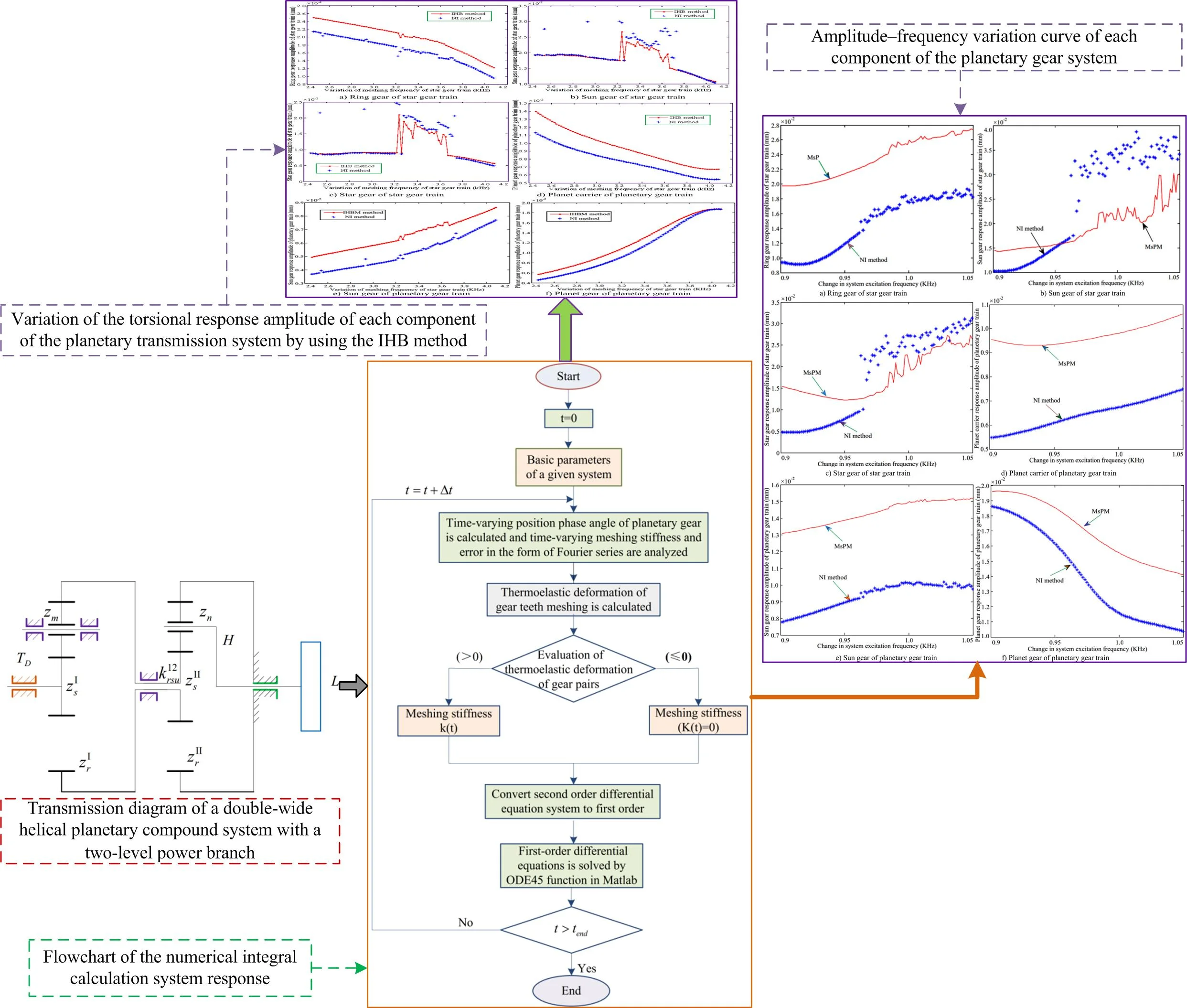
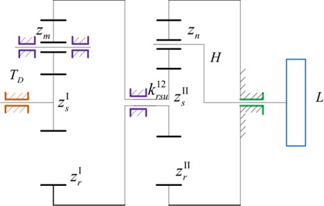
The transmission diagram of the double-wide helical planetary compound system, with a two-level power branch, for high speed and heavy duty applications, is shown in Fig. 3. The system is composed of a star gear train I (sun gear , planet gear , and ring gear ) that is connected to a planet gear train II (sun gear , planet gear , ring gear , and planet carrier ). The superscripts I and II correspond to the series of the component. The input power is transmitted to the load by the sun gear . The input speed of the second-stage planetary gear train is reduced according to the deceleration of the first stage planetary gear train, thereby increasing the stability and smoothness of the transmission. The system parameters are listed in Table 1 and Table 2. The calculated nonlinear response characteristics of the system are shown in Figs. 4 to 6, which correspond to the time domain response history, phase diagram, and Poincare mapping of the system, respectively. Owing to the space constraints in this manuscript, we have only mentioned the torsional response of the representative components. However, this does not imply that the translational response of the components can be neglected.
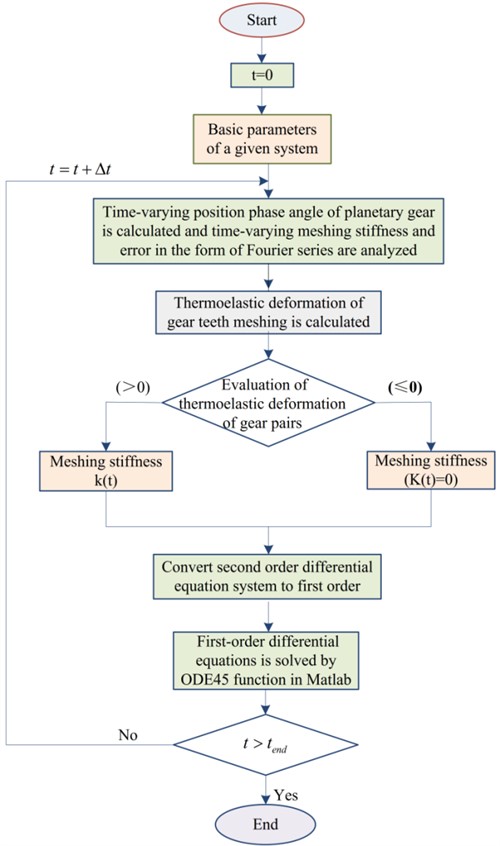
Since the number of unknowns exceeds the number of equations, the expected increment must be specified before performing the actual calculation. The increment specified in this article is equal to . Based on the structural flowchart of the improved incremental harmonic balance method depicted in Fig. 4 and the dimensionless parameters listed in Table 1 and Table 2, the specific iterative process of the improved method is given as follows.
Fig. 3Transmission diagram of a double-wide helical planetary compound system with a two-level power branch
(1) The initial value is fixed according to the excitation frequency .
(2) The increment is obtained by substituting the value of in Eq. (18). Replace with to obtain the updated values of from Eq. (18). This is used to obtain from Eq. (17). The modified solution is then obtained from Eq. (12). The process is repeated until the value of satisfies .
(3) A new increment is provided to such that . The value of that is obtained in (2) is set as the initial value. The harmonic balance process is repeated and the value of is updated until it meets the condition .
(4) The arc length parameter is introduced to determine the initial value of the next point from the value of and obtained in Eqs. (2) and (3). This is substituted as the initial value in Eq. (18), and the iteration step mentioned in Eq. (2) is repeated.
Fig. 4Flowchart of the numerical integral calculation system response
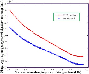
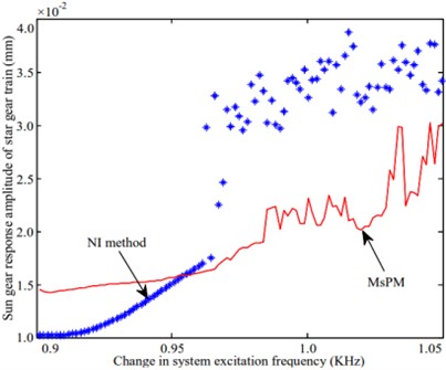
The amplitude-frequency characteristic curves of the system operating at the approximate working speed are shown in Fig. 5. The figure compares the results obtained by the incremental harmonic balance method and those obtained by the numerical integration (NI) method. The latter is based on the 4th and 5th step variable step Runge-Kutta method.
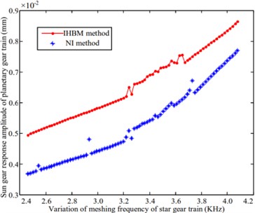
The meshing frequency lies in the range of 3.3-3.7 kHz, as shown in Figs. 5(a), (b) and (c). Amplitude jumps are observed in both the sun gear and star gear of the star gear system. The two methods are in this area. The amplitude values obtained from both the methods do not match as well in this region as they do in the others. In addition, the results of the numerical integration method indicate the presence of a resonance peak in other regions; however, the IHB method does not seem to indicate the presence of a resonance peak. This is because the number of harmonic response terms is insufficient.
Table 1System parameters
Physical quantity \Transmission parts marking | Sun gear | Ring gear | Planet carrier | Star / Planet gears | ||||
Level 1 | Level 2 | Level 1 | Level 2 | Level 1 | Level 2 | Level 1 | Level 2 | |
Quality (kg) | 102 | 398 | 258 | 647 | 1300 | 300 | 647 | |
Equivalent moment of inertia (kg) | 51.5 | 199 | 244 | 613 | 1300 | 150 | 324 | |
Base circle diameter (mm) | 385.27 | 479.24 | 1700.84 | 1700.84 | 657.78 | 610.80 | ||
Number of teeth | 41 | 51 | 181 | 181 | 70 | 65 | ||
Meshing stiffness (N/m) | ; ; ; | |||||||
Support stiffness (N/m) | ; ; | |||||||
Torsional stiffness of central member (N/m) | ||||||||
Torsional stiffness of shaft (Nm/rad) | ||||||||
Pressure angle () | ||||||||
Helix angle () | ||||||||
Fig. 5Variation of the torsional response amplitude of each component of the planetary transmission system by using the IHB method
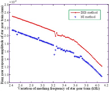
a) Ring gear of star gear train
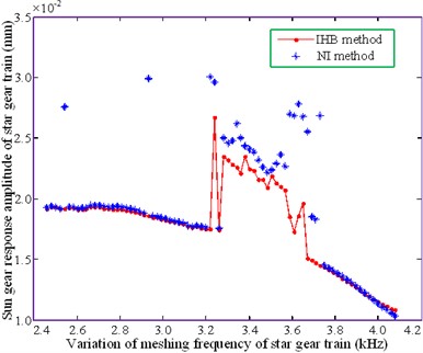
b) Sun gear of star gear train
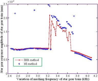
c) Star gear of star gear train
d) Planet carrier of planetary gear train
e) Sun gear of planetary gear train
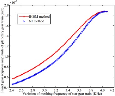
f) Planet gear of planetary gear train
Table 2Dimensionless parameters
Parameter representation | Star gear train | Planetary gear train |
Dimensionless parameter | ||
Dimensionless parameter | ||
Dimensionless meshing frequency | ||
Damping ratio | ||
Dimensionless error amplitude | ||
The ring gear of the star gear system, shown in Figs. 5(a), (b) and (c), and the sun gear of the planetary gear system, shown in Fig. 5(e), produces minimal amplitude resonance. The results obtained by the numerical method and IHB method follow a similar trend; however, a significant difference exists between the amplitude values. The variations in the amplitude of the planetary carrier, shown in Fig. 5(d), and the planetary gears, shown in Fig. 5(f), are relatively gentle. The curves obtained from the two methods gradually tend to become consistent with increasing mesh frequency, resulting in a significant amplitude variation of the planetary gears. This is consistent at a 4.0 kHz bit frequency. The above analysis demonstrates that the improved method is in agreement with the law of amplitude-frequency change for each part of the system, thereby illustrating the feasibility of this method.
5. Application of the multi-scale perturbation analysis method
The incremental harmonic balance method, which is based on the arc-length continuation technique, is a semi-analytical and semi-numerical method. It is necessary to perform a purely analytical study of the dynamic characteristic equation of the system. Current studies adopt the multi-scale perturbation analysis method to obtain the analytical solutions of parametric excitation and gap nonlinear system equations [31]. The multi-scale perturbation method (MsPM) can obtain the analytical frequency response functions of a system, including the fundamental, subharmonic, and superharmonic resonance responses. Thus, this technique demonstrates the impact of important parameters on the response of the nonlinear dynamic characteristics, unlike conventional numerical methods.
The small parameter , is introduced in the first-order Fourier coefficient of the meshing stiffness of the sun and planetary gears in the planetary gear system. refers to the average meshing stiffness and is written in its dimensionless form for each gear pair:
where:
The time required for the contact gear pair to disengage is assumed to be negligible with respect to the response period, i.e., , where is the disengagement time, and is the response period. The Fourier expansion of the non-meshed function of the contact gear pair is expressed in terms of the fundamental frequency , as follows:
The corresponding eigenvalue of Eq. (11) is expressed as:
where is the linear time-invariant average meshing stiffness matrix, and . represents the change range matrix of the average meshing stiffness , with its mean value equal to zero. is the support torsional stiffness matrix (including the support stiffness of the star and planet gears). is the additional stiffness matrix generated due the transient phase angle of the planetary gear. , where, , and are the coefficient matrices related to, , and, respectively.
The vibration mode is given by , and it satisfies the relation . The average stiffness matrix is given below:
where , , , and are the coefficient matrices related to , , , and .
Substituting Eqs. (25)-(28) into Eqs. (11), we obtain:
where:
The modal coordinate transformation can be used to write the additional stiffness matrix coefficients in terms of the small parameters. The resulting modal coordinate form, obtained after the transformation of the Eq. (31), is given as:
where, , , , , , .
, , and represent the elements in the th row and th column of the matrices , , and , respectively. , , , and represent the elements in the row and the th column of the matrices , , , and , respectively. The modal damping factor has been introduced and rewritten in terms of the small parameter as . , where is the speed of the second stage planet carrier. The small parameter is related to the time change of the phase angle of the planet gear in the second stage.
A multi-scale method is applied by introducing multi-scale variables such as and . Based on the abovementioned variables, the perturbation equation with the first approximate solution is proposed, as shown below:
Eq. (34) is the perturbation equation used to calculate the closed solution. The frequency response characteristics of the system under different excitations can be studied by using this equation.
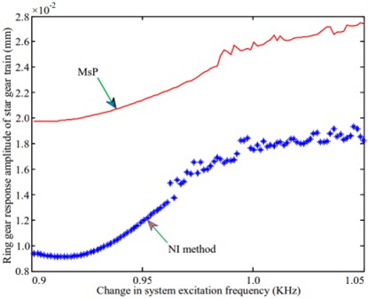
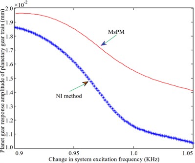
Fig. 6Amplitude-frequency variation curve of each component of the planetary gear system
a) Ring gear of star gear train
b) Sun gear of star gear train
c) Star gear of star gear train
d) Planet carrier of planetary gear train
e) Sun gear of planetary gear train
f) Planet gear of planetary gear train
6. Analysis of the frequency response characteristics
The amplitude-frequency characteristics of the system are obtained and studied after solving the frequency response equations under different resonance conditions according to the multi-scale perturbation analysis method.
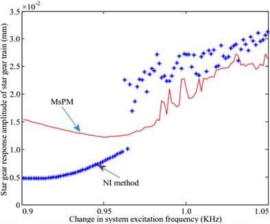
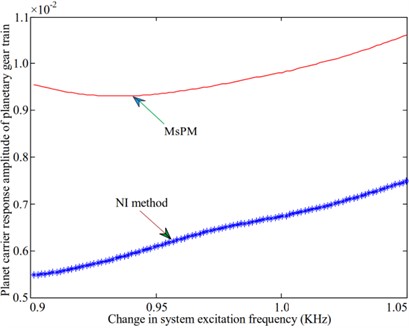
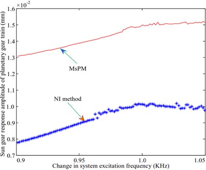
A natural frequency of 973.1 Hz is selected to study the frequency response characteristics of the system during resonance in the vibration mode of the planetary gear system. The amplitude-frequency characteristics of the system are analyzed and compared with the results obtained by using the numerical integration method. The calculated amplitude-frequency characteristic curve is shown in Fig. 6. Fig. 6(a) shows that the response amplitude of the ring gear of the star gear train calculated by the multi-scale method is differs significantly from that of the numerical method. However, the trends followed by the variation of the responses in both methods are identical, as shown in Fig. 6(e). The variation of the sun gear in the middle planetary gear system is similar to that of the ring gear in the star gear system. The response amplitudes of the sun gear and the star gear in the star gear system are not consistent with those obtained from the numerical method. The variation trends obtained through both methods were also different. No amplitude jump was observed, as shown in Figs. 6(b) and 6(c). The variation trends of the planetary carrier and gears of the planetary gear train, as shown in Figs. 6(d) and 6(f), are identical. The larger difference is also the magnitude of the amplitude. The difference between the values of the amplitude obtained through both methods is relatively large for the planet carrier and small for the planet gear.
The impact of the variation of the damping ratio on the amplitude-frequency response characteristics, upon the introduction of the 3rd harmonic error, is studied. It can be seen from Fig. 7 that the bifurcation characteristics of the system are complex, and the introduction of errors increases the influence of the damping ratio. After increasing the damping ratio, the response amplitude of sun and star gears in the star gear system is reduced. The component response amplitude has increased. In the follow-up research, the influence of the damping ratio on the system’s amplitude-frequency characteristics can be further confirmed.
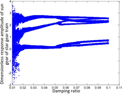
Fig. 7Bifurcation diagram of the variation of damping ratio with the error
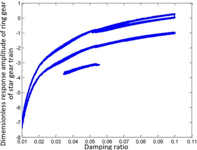
a) Ring gear of star gear train
b) Sun gear of star gear train
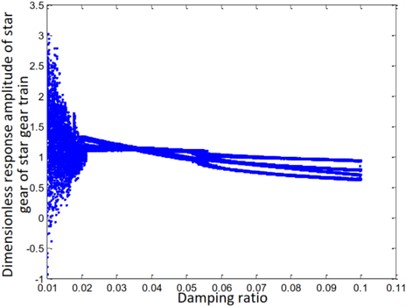
c) Star gear of star gear train
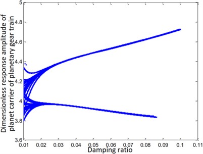
d) Planet carrier of planetary gear train
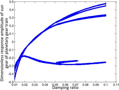
e) Sun gear of planetary gear train
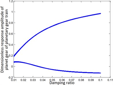
f) Planet gear of planetary gear train
The steady-state response of the ring and sun gears of the star gear train is either a non-harmonic periodic response or a simple harmonic periodic response, as shown in Figs. 7(a) and (e). The gears of the planetary gear train always maintain a harmonic response without bifurcation, as shown in Fig. 7(f). The steady-state response of the planetary carrier of the planetary gear train, as shown in Fig. 7(d), is bifurcated from a single period to a double period when the damping ratio is equal to 0.03. The steady-state response of the sun gear of the star gear system, as shown in Fig. 7(b), directly branches from period doubling to a harmonic period response at , and attains a chaotic state at . The steady-state response of the star gear, as shown in Fig. 6(c), involves a period-doubling bifurcation from a single-cycle bifurcation at . The steady-state response then bifurcates from period-doubling to a chaotic state at .
The nonlinear response characteristics are depicted through a phase diagram of the system-time domain in Fig. 8. The phase diagrams shown in Figs. 8(a), (b), and (c) form a closed curve loop, irregular shape, and an open curve, respectively. The phase diagrams shown in Figs. 8(d) and (f) are ellipses. The response carrier of the planetary gear train produces a pseudo-periodic response, as shown in Fig. 8(e).
The above analysis shows that the results obtained by the multi-scale method can predict the trend of variation of the responses of each component in a few regions. However, it produces linear changes in the region involving an increase in the amplitude. This behavior is attributed to the fact that only one approximate solution was obtained in this study. It is very difficult to increase the order of the solution for a nonlinear system having multiple degrees of freedom. Thus, the numerical method of calculation is more suited to be the main method, with the analytical method serving as an auxiliary option.
Fig. 8Phase plan of the composite transmission system
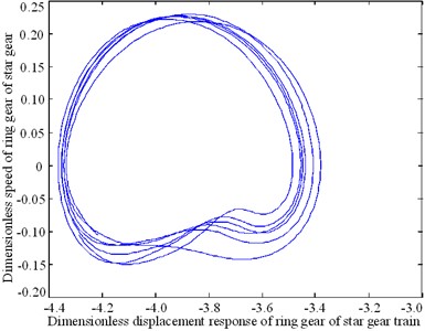
a) Ring gear of star gear train
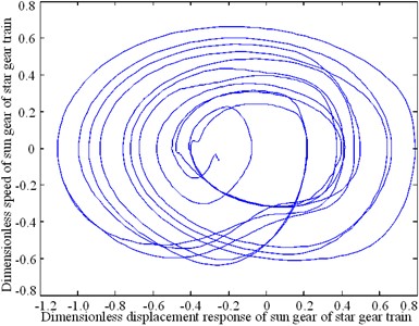
b) Sun gear of star gear train

c) Star gear of star gear train
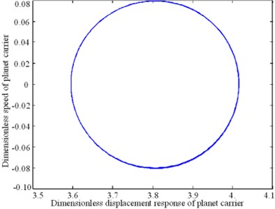
d) Planet carrier of planetary gear train
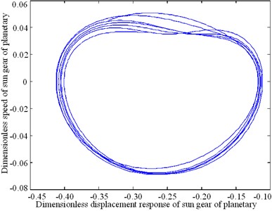
e) Sun gear of planetary gear train
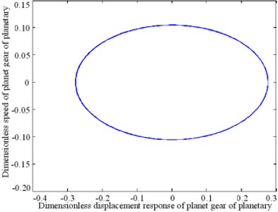
f) Planet gear of planetary gear train
7. Conclusions
The current paper proposes the application of the semi-numerical incremental harmonic balance and semi-analytical multi-scale perturbation methods to a two-stage series compound planetary transmission system. Through this study, we attempt to solve the dynamic characteristic equation of a two-stage series composite planetary transmission system through an analytical calculation.
The arc-length continuation technology is introduced to improve the incremental harmonic balance method. The improved method is used to calculate and analyze the amplitude-frequency characteristics of the system. The feasibility and effectiveness of the method are verified by comparing the results with those obtained using the numerical integration method.
The analytical multi-scale perturbation method is then applied to a two-stage series compound planetary transmission system. The frequencies of the main resonance, subharmonic resonance, and superharmonic resonance are obtained. A comparison between the current results and those obtained from the numerical integration method suggests that it is feasible to use the multi-scale method to analyze the two-stage series compound planetary transmission system. However, the results may not be accurate in some regions.
References
-
Inalpolat M., Kahraman A. A theoretical and experimental investigation of modulation sidebands of planetary gear sets. Journal of Sound and Vibration, Vol. 323, Issues 3-5, 2009, p. 677-696.
-
Feng Z. P., Zuo M. J. Vibration signal models for fault diagnosis of planetary gearboxes. Journal of Sound and Vibration, Vol. 331, Issue 22, 2012, p. 4919-4939.
-
Hotait M. A., Kahraman A. Experiments on the relationship between the dynamic transmission error and the dynamic stress factor of spur gear pairs. Mechanism and Machine Theory, Vol. 70, 2013, p. 116-128.
-
He G. L., Ding K., Li W. H., Li Y. Z. Frequency response model and mechanism for wind turbine planetary gear train vibration analysis. IET Renewable Power Generation, Vol. 11, Issue 4, 2017, p. 425-432.
-
Pan C. D., Yu L., Liu H. L., Chen Z. P., Luo W. F. Moving force identification based on redundant concatenated dictionary and weighted l1-norm regularization. Mechanical Systems and Signal Processing, Vol. 98, 2018, p. 32-49.
-
Chen Z., Chan T. H. T., Nguyen A., Yu L. Identification of vehicle axle loads from bridge responses using preconditioned least square QR-factorization algorithm. Mechanical Systems and Signal Processing, Vol. 128, 2019, p. 479-496.
-
Suslin A., Pilla C. Study of loading in point-involute gears. Procedia Engineering, Vol. 176, 2017, p. 12-18.
-
Morgado T. L. M., Branco C. M., Infante V. A failure study of housing of the gearboxes of series 2600 locomotives of the Portuguese Railway Company. Engineering Failure Analysis, Vol. 15, Issues 1-2, 2008, p. 154-164.
-
Hu W. G., Liu Z. M., Liu D. K., Hai X. Fatigue failure analysis of high speed train gearbox housings. Engineering Failure Analysis, Vol. 73, 2017, p. 57-71.
-
Weis P., Kučera Ľ., Pecháč P., Močilan M. Modal Analysis of Gearbox Housing with Applied Load. Procedia Engineering, Vol. 192, 2017, p. 953-958.
-
Lin T. L., Zhang K. An analytical study of the free and forced vibration response of a ribbed plate with free boundary conditions. Journal of Sound and Vibration, Vol. 422, 2018, p. 15-33.
-
Zhou H. A., Zhao Y. G., Wu H. Y., Meng J. B. The vibroacoustic analysis of periodic structure-stiffened plates. Journal of Sound and Vibration, Vol. 481, 2020, p. 115402.
-
Sánchez M. B., Pleguezuelos M., Pedrero J. I. Approximate equations for the meshing stiffness and the load sharing ratio of spur gears including hertzian effects. Mechanism and Machine Theory, Vol. 109, 2017, p. 231-249.
-
Liang X., Zuo M. J., Feng Z. Dynamic modeling of gearbox faults: a review. Mechanical Systems and Signal Processing, Vol. 98, 2018, p. 852-876.
-
Ege K., Roozen N. B., Leclère Q., Rinaldi R. G. Assessment of the apparent bending stiffness and damping of multilayer plates; modelling and experiment. Journal of Sound and Vibration, Vol. 426, 2018, p. 129-149.
-
Marchetti F., Ege K., Leclère Q., Roozen N. B. On the structural dynamics of laminated composite plates and sandwich structures; a new perspective on damping identification. Journal of Sound and Vibration, Vol. 474, 2020, p. 115256.
-
Garambois P., Donnard G., Rigaud E., Perret Liaudet J. Multiphysics coupling between periodic gear mesh excitation and input/output fluctuating torques: Application to a roots vacuum pump. Journal of Sound and Vibration, Vol. 405, 2019, p. 158-174.
-
Acri A., Nijman E., Conrado E., Offner G. Experimental structure-borne energy flow contribution analysis for vibro-acoustic source ranking. Mechanical Systems and Signal Processing, Vol. 115, 2019, p. 753-768.
-
Yang Y., Fenemore C., Kingan M. J., Mace B. R. Analysis of the vibroacoustic characteristics of cross laminated timber panels using a wave and finite element method. Journal of Sound and Vibration, Vol. 494, 2021, p. 115842.
-
Wu H., Wu P. B., Li F. S., Shi H. L., Xu K. Fatigue analysis of the gearbox housing in high-speed trains under wheel polygonization using a multibody dynamics algorithm. Engineering Failure Analysis, Vol. 100, 2019, p. 351-364.
-
Wang Q. B., Zhao B., Fu Y., Kong X. G., Ma H. An improved time-varying mesh stiffness model for helical gear pairs considering axial mesh force component. Mechanical Systems and Signal Processing, Vol. 106, 2018, p. 413-429.
-
Dai H., Long X. H., Chen F., Bian J. Experimental investigation of the ring-planet gear meshing forces identification. Journal of Sound and Vibration, Vol. 493, 2021, p. 115844.
-
Kosała K. Calculation models for analysing the sound insulating properties of homogeneous single baffles used in vibroacoustic protection. Applied Acoustics, Vol. 146, 2019, p. 108-117.
-
Rosa S. D., Desmet W., Ichchou M., Ouisse, Scarpa F. Vibroacoustics of periodic media: multi-scale modelling and design of structures with improved vibroacoustic performance. Mechanical Systems and Signal Processing, Vol. 142, 2020, p. 106870.
-
Bi S. F., Ouisse M., Foltête E., Jund A. Virtual decoupling of vibroacoustical systems. Journal of Sound and Vibration, Vol. 401, 2017, p. 169-189.
-
Arasan U., Marchetti F., Chevillotte F., Tanner G., Chronopoulos D., Gourdon E. On the accuracy limits of plate theories for vibro-acoustic predictions. Journal of Sound and Vibration, Vol. 493, 2021, p. 115848.
-
Daneshjou K., Talebitooti R., Kornokar M. Vibroacoustic study on a multilayered functionally graded cylindrical shell with poroelastic core and bonded-unbonded configuration. Journal of Sound and Vibration, Vol. 393, 2017, p. 157-175.
-
Rohan E., Lukeš V. Homogenization of the vibro-acoustic transmission on perforated plates. Applied Mathematics and Computation, Vol. 361, 2019, p. 821-845.
-
Guo Y., Eritenel T., Ericson T. M., Parker R. G. Vibro-acoustic propagation of gear dynamics in a gear-bearing-housing system. Journal of Sound and Vibration, Vol. 333, Issue 22, 2014, p. 5762-5785.
-
Tomilina T. M. New approaches to design of structures with required vibroacoustic properties. Procedia Engineering, Vol. 106, 2015, p. 350-353.
-
Li Y. Z., Ding K., He G. L., Yang X. Q. Vibration modulation sidebands mechanisms of equally-spaced planetary gear train with a floating sun gear. Mechanical Systems and Signal Processing, Vol. 129, 2019, p. 70-90.
About this article

The authors would like to thank the Northeast Forestry University (NEFU), Heilongjiang Institute of Technology (HLJIT), and the Harbin Institute of Technology (HIT) for their support.
The research topic was supported by the Doctoral Research Startup Foundation Project of Heilongjiang Institute of Technology (Grant No. 2020BJ06, Yongmei Wang, HLJIT), the Natural Science Foundation Project of Heilongjiang Province (Grant No. LH2019E114, Baixue Fu, HLJIT), the Basic Scientific Research Business Expenses (Innovation Team Category) Project of Heilongjiang Institute of Engineering (Grant No. 2020CX02, Baixue Fu, HLJIT), and the Special Project for Double First-Class-Cultivation of Innovative Talents (Grant No. 000/41113102, Jiafu Ruan, NEFU).
