Abstract
In this research subtopic, an electro-hydraulic servo four-legged heavy load (FLHL) robot has been designed and developed. This paper proposes an integration layout cylinder design scheme for a non-lightweight hydraulic servo four-legged robot with high loads and torques of hip joint, and derives the mathematical element analysis model for a parallel hydraulic servo cylinder system. The multiple inherent characteristics of the parallel-executed cylinder integration system model are further explored. Based on the controllable functional requirements of interconnected joints and weakening the influence of internal force coupling, a design idea of force/position hybrid control scheme for the parallel-executed cylinder is determined, and then the force/position signal module design unit is used to reversely solve the force/position hybrid control. Considering the inherent requirements of the servo-executed cylinder force control unit module, the implementation process of magnetic flux compensation and speed compensation is discussed in detail. The minimum amplitude controller is applied to the servo-executed cylinder force unit module, and the proportional integrated controller has been determined in the servo-executed cylinder position control unit module. A compound control strategy proposed in this paper is verified on a parallel hydraulic servo platform. The experimental verification results reveal that the values of position/force attenuation amplitude and lag phase are not greater than 9 % and 18°, respectively. In addition, the feasibility of the interconnected implementation of the hybrid control scheme proposed in this paper is further deepened. The effective conclusion of this research will be accepted in the application field of FLHL robot control system.
Highlights
- An electro-hydraulic servo four-legged heavy load (FLHL) robot is designed and developed.
- An integration layout cylinder design scheme for a non-lightweight hydraulic servo four-legged robot with high loads and torques of hip joint is proposed.
- Mathematical element analysis model for a parallel hydraulic servo cylinder system is derived.
- Multiple inherent characteristics of the parallel-executed cylinder integration system model are further explored.
- A design idea of force/position hybrid control scheme for the parallel-executed cylinder is determined, and the force/position signal module design unit is used to reversely solve the force/position hybrid control.
- A compound control strategy is verified on a parallel hydraulic servo platform, and the feasibility of the interconnected implementation of the hybrid control scheme is further deepened.
1. Introduction
In recent years, many scholars have attached great importance to the research of heavy load robots. A four-legged robot that would become to simulate ordinary animals has evolved into a hot bionic topic recently. Compared with unipedals and bipeds, hydraulic four-legged robots have better ability and stability to carry heavy objects. And compared with hexapods and robots with more legs, it also reduces redundancy in structural design. Therefore, extensive research and development have been conducted on hydraulic quadruped robots. A hydraulic four-legged robot has been evolved and developed by multi-legged robots in many aspects (such as structure and motion form).
In the current research, many scholars have made some achievements in the research of hydraulic four-legged robots. As its drive unit has the characteristics of a larger initial starting force/precise position, higher power density and compact high-strength structure and so on. So far, many electro-hydraulic servo actuators have been adopted in some special engineering industries. The outstanding dynamic response characteristics of hydraulic four-legged robots immediately have attracted widespread attention in the field of electromechanical engineering applications. Boston Power Corporation (BPC) recently declared that it has begun researching and pre-developing lightweight hydraulic four-legged robots, such as Wildcat, Big Dog and SPOT, LS3, and others [1, 2].
So far, based on the background impact of this research topic, some scientific research concerns in the field of hydraulic servo FHL robots have been launched in many countries. Several brands of hydraulic four-legged robots have designed and developed the Advanced Robotics Division of Italian Industrial Robotics (IIT) [3], a multifunctional robot system with hydraulic drive has been developed successively, such as HyQ, MiniHyQ and HyQ2Max brands as shown in Fig. 1. A four-legged robot named Jinpoong has also successfully developed and grandly launched by the Korea Institute of Science and Technology [4].
Many domestic universities and research institutions, such as Harbin Institute of Technology, Northeast Forestry University and Shandong University have carried out research on hydraulic four-legged robots related topics [5-8].
To the author’s knowledge, with the exception of the robot called LS3, the connection positions of the hip joints of the four-legged robot are controlled and driven by a single hydraulic actuator. Also HyQ uses a single electric motor, but the difference is that a single electro-hydraulic servo actuator has been widely adopted by other robots. For the research topic, a two-cylinder electro-hydraulic actuator cylindrical transmission technology solution is proposed. The payload of the robot LS3 reaches 181 kg. Taking into account the special project background of Boston's dynamic characteristics, the report on the robot LS3 does not have much technical reference data [9]. So far, hydraulic four-legged motion has always been a critical focus of discussion in current heavy load robot research. A four-legged platform parallel servo cylinder transmission system with force/position control hydraulic integrated technology is rarely studied in the current research field [10].
Fig. 1Physical images of a hydraulic four-legged robot a) in 2012, robot images with stereo cameras were not installed, b) in 2012, robot images with stereo cameras were installed
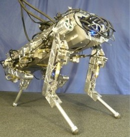
a)
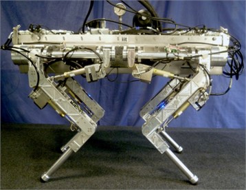
b)
Walking (or legged) robots have been an exciting area of research for the past few decades [11-13]. The study of electro-hydraulic servo-type four-legged robots further found that the real-time control of hip motion process is extremely complex, which is associated with elements from 4 rotating joints as well as hydraulic actuators for 4 symmetrical legs and single leg to a hinged trunk with controllers and sensors [14]. Next thing to study, many tasks in kinematics and dynamics simulation, as well as optimal design of mechanical structure for hydraulic actuated four-legged robot will be completed. A four-legged robot with 4 DOFs per supporting leg has motion redundancy to better adapt to rugged terrain [15].
Similar to the search on related topics, scholars mostly assume that the distance between the foot and the rolling axis of the hydraulic actuated four-legged robot studied in these subjects is larger, and the design required driving torque is larger under the same foot end force [16]. Gehring et al [17] analyzed in detail the impact of supporting leg impedance on leg gait stability and efficiency. In this way, from the author's review of the literature, it is known that few researchers have actively contributed to the dynamic motion posture of four-legged robots. However, it is well known that tetrapods in nature usually twist, dive or bend their trunks to walk, run or crawl [18-20]. The turning strategy of a four-legged robot based on leg gait was mentioned by Liu et al [21]. The transition between single supporting leg of the four-legged robot and walking posture was studied by Zhang et al [22]. In practical applications of the real nature, these research results on leg gaits of twisted torso have been widely popularized. Undoubtedly, it will bring endless advantages to the movement of the inherent tripod structure, especially during the fast and heavy load hydraulic robot movements. Similarly, a twisted torso will also contribute to the leg gaits of a hydraulic four-legged robot. Therefore, the study of torsional trunk gait of FLHL robots has high value practical guiding significance.
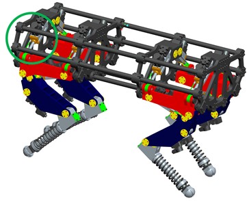
Based on increasing the output pressure and effective equivalent area of an electro-hydraulic servo execution cylinder, the required driving torque is achieved and obtained by means of adopting methods such as multi-cylinder parallel. The fuel supply pressure of a hydraulic system is restricted by the amplitude of the hydraulic components, which makes it difficult to increase further indefinitely. Since the increase of the equivalent area of the electro-hydraulic servo execution cylinder will inevitably add additional torque it bears, but it is difficult to increase the design size due to the structural limitation (the green parallel hydraulic larger cylinder has a small running space margin) (the green and red circle are shown in Fig. 4), which in turn limits the interchange cycle of the actuators with electro-hydraulic servo control function will be increased, and the manufacturing cost will also be raised.
In view of the above factors, the design technology of the multi-cylinder electro-hydraulic parallel structure shall be an ideal choice for achieving the torque output of heavy load four-legged motors. Compared with wheeled robots in rough terrain, it has irreplaceable advantages. Therefore, FLHL robots have always been one of the most attractive research directions of focus points in the field of multi-legged robots.
Considering the larger bearing loads and torque characteristics of the hip joints for a heavy load hydraulic four-legged robot, a parallel servo cylinder driving element model is proposed in this subject research.
In view of the hybrid control performance of roller joint position and the output force used for driving, the numerical analysis model of a parallel servo-executed hydraulic cylinder system is proposed, the solution of mathematical theory model is explored and the decoupling algorithm of the parallel electro-hydraulic servo-executed cylinder force/position hybrid control is constructed. Taking into account the force control model characteristics of an electro-hydraulic parallel actuator, a minimal integrated controller is developed to optimize the design of driving force control. The semi-physical system with parallel cylinders is used to verify the hybrid force/position control strategy, and the feasibility of the proposed control scheme is checked by actual operating experiments in this research project.
2. Kinesiology modeling and parameters adjustable analysis of robot mechanical system
2.1. Analysis of transmission form of a double electrohydraulic cylinder
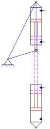
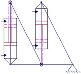
Most researchers only focus on the periodic and time-varying amplitude characteristics of joint angles, but often ignore the force/position stability of continuous motion trajectories. The stable force/position hybrid control of a FLHL robot plays a vital role in the motion of parallel servo execution cylinder transmission system, which is affected by the constraints of the electro-hydraulic servo actuator. It is worth mentioning that the motion form of the four-legged robot is derived from the imitation of the animal's walking posture in nature. The motion forms of an electro-hydraulic servo cylinder (ESC) are the representation of the gait of the FLHL robot. A joint illustration of a heavy load four-legged robot driven by an electro-hydraulic fuel pressure is shown in Fig. 2. In Fig. 2, the movement trajectory of the parallel actuator of the electro-hydraulic servo cylinder is numerically simulated. The three connection points of the bottom of the electro-hydraulic servo actuator cylinder, its associated axis and the end of the piston rod are expressed as A, B and C, respectively. For this point, the position is described when the hydraulic cylinder is fully extended to ensure that the FLHL robot always moves in a preset direction. It can be seen from the above-mentioned figures that the torsional trajectory of the hydraulic cylinder of the four-legged robot is a prerequisite for the normal operation of the parallel actuator. As switching the driving mode to a dual electric-hydraulic servo cylinder, the bottom active range of the other electro-hydraulic servo cylinders must be located outside the sector area composed of and . At this time, a fixed center exists in the transmission joint of the electric hydraulic cylinder, which is difficult to achieve its expected form of motion.
Fig. 2Structure diagram of an electro-hydraulic servo actuator in parallel form
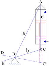
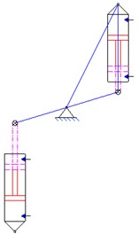
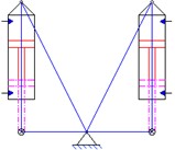
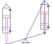
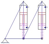
Fig. 3Layout diagrams of a parallel electro-hydraulic cylinder for the study
a)
b)
c)
d)
e)
f)
As can be easily seen in the forms shown in Fig. 3(a) and 3(b), the form of motion of the electro-hydraulic cylinder has nothing to do with the twist of a FLHL manipulator body. It can be known that the body translation of the FLHL robot has no effect on its horizontal coordinates. It can also be seen from the above analysis that another electro-hydraulic servo actuating cylinder and its bottom end movement range should not exceed the sector area enclosed by and . Once the point is precisely controlled in the area , the structural layout of a FLHL robot is described in the Fig. 3. These methods can easily cause motion disturbance of the leg support structure of the FLHL robot in the internal and external pendulums. In the Figs. 3(a) and 3(b) have broken through the overall width limit of the FLHL robot, and then it is concluded that the torso torsion behaviour is independent of the body motion of the robot on the horizontal coordinate. If using the designed form of the Fig. 3(d), the two electro-hydraulic cylinders are located on both sides of the joint axis. Assuming that this research topic adopts the layout design form shown in Fig. 3(d), two electro-hydraulic servo actuator cylinders are mounted on both sides of the joint axis. Herein, as can be seen from Fig. 3(c), the two electro-hydraulic actuators are set in the arrangement form of the same orientation of the articulated joint, thereby eliminating the existence of similar factors in Fig. 3(d). In view of these issues, the structure form shown in Figure c is selected and used for the current project subject of this study. In Fig. 3(d), the parallel arrangement form of a double electro-hydraulic cylinder is pre-developed. Based on the above analysis, it can be seen that the force vector of the electro-hydraulic actuator at the hinge joint is different in the positive/negative directions, as shown in the Fig. 3(e). The connection form in Fig. 3(e) is the best choice for this project subject. In view of the fact that the rotation angle of the rotary joint is set to exceed 45°, the electro-hydraulic actuating cylinder must be connected to a fixed position at the hinge joint. If only by increasing the length of the supporting leg, the effect of the angle-constraining effect of the articulated joint will promote the joint rotation angle, which is contrary to the original design requirements of the FLHL robot compact structure. For the Fig. 3(f), the positive/negative directions can ensure that the electro-hydraulic cylinder at the hinge joint has an equivalent applied force, which is an ideal layout design form. The comprehensive influencing factors take into account the dynamic changes in the form of the link mechanism, which makes it difficult to perform real-time replacement of electro-hydraulic servo actuators.
2.2. Modeling of a servo actuator with electro-hydraulic
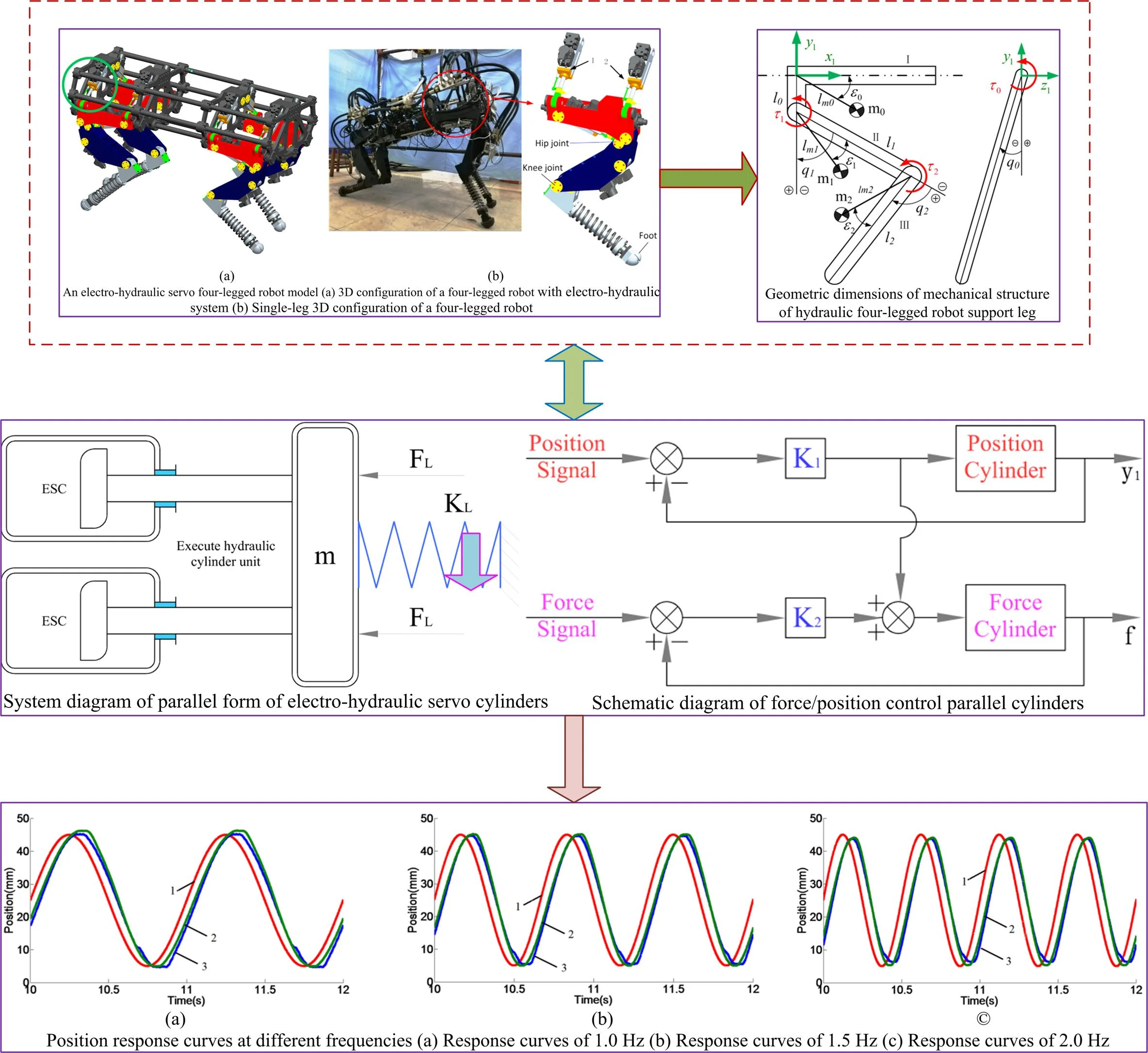
The posture stability of the force/position of the heavy load hydraulic four-legged robot during the motion is further revealed and ensured. The strategy of electro-hydraulic servo actuator control (ESAC) is launched and the PD control method is selected to track the joint angles in real-time operating conditions. The feasibility of the technical solution of the current topics is analyzed in detail, and the results have been verified by kinetic analysis simulations finally. In the movement of a heavy load four-legged hydraulic robot, various forms of motion posture trajectories are planned by tracking the real-time changes of the joint angles to ensure the smoothness, in turn, the trajectory deviation of the torsional driving torque and the robot's movement posture is reduced. A 3D model of a quadruped robot driven by a parallel execution cylinder with a servo system for the research topic of this article is shown in Fig. 4. The four-legged robot with an electro-hydraulic servo cylinder has active/passive degrees of freedoms, of which, the active degrees of freedom are 12 and the passive degrees of freedom are 4. The robot system studied consists of 16 actuators of the same model with electro-hydraulic servo function. It is worth emphasizing that the four-bar hinged connection rolling joint is driven by two actuators with an electro-hydraulic servo system to increase the torsional driving torque of the connection position of its hinge joint. In the further research of this subject, an equivalent analysis model of the required electro-hydraulic servo actuator is proposed and captured. The author proposes the following assumptions: (1) Moment of inertia of a four-legged robot single-leg mechanism with an ESAC around its rolling axis is identified as . (2) Torsional moment of the rolling axis is represented as . (3) For the damping spring and joint axis, the equivalent characterization of its stiffness is noted .
As shown in Fig. 5, an equivalent model of the actuator with electro-hydraulic servo function is established in view of the modular planning method and the controllable framework, which complying with the equivalent principle of load balancing of a parallel servo cylinder with electro-hydraulic system.
Fig. 5 reveals a parallel electro-hydraulic servo actuator for the scroll axis, which is a representative redundant driving system. Considering that the asynchronous operation of the two actuators will generate a greater internal force, which may also greatly weaken the necessary driving torques of the actuators.
Fig. 4An electro-hydraulic servo four-legged robot model: a) 3D configuration of a four-legged robot with electro-hydraulic system, b) single-leg 3D configuration of a four-legged robot
a)
b)
Fig. 5System diagram of parallel form of electro-hydraulic servo cylinders
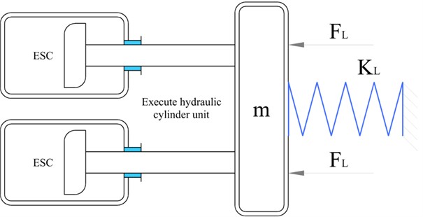
Herein , , , is defined as a distance parameter between the scroll axis and the joint loading of the parallel servo actuator with an electro-hydraulic piston rod.
To avoid the interference of asynchronous motion, the attention will be paid to the position of a servo actuator with electro-hydraulic in its control mode. According to the related research in the reference [23-26], as shown in Eq. (1), the transfer function expression of the single-cylinder servo system with an electro-hydraulic position should be derived:
Among them, represents the effective regions of the servo cylinder piston, indicates the gain features for an amplifier with servo function, indicates the parameter of flow gain, for a servo controllable regulating valve, represents the integrated natural frequency of the system, indicates the comprehensive damping ratio of the system, represents the stiffness parameter of the hydraulic equivalent spring, represents the load equivalent spring stiffness variable of the aforementioned spring, expresses the total flux pressure coefficient of the cylinder, represents an external comprehensive interference force of the system, which indicates both the externally applied loading force and the internal inherent force based on the asynchronous movement of the hydraulic servo cylinder, represents the volume parameter (elastic modulus) of a particular hydraulic oil, indicates the displacement parameter output by the hydraulic servo cylinder.
2.3. Motion analysis of double linear electrohydraulic servo cylinder
In view of the installation error of the linear servo actuator with an electro-hydraulic, the manufacturing of the displacement sensor and the measurement error and the dynamic performance difference, which make it difficult to ensure the synchronization of servo actuators and electro-hydraulic movements. Since the servo actuators and the joints are rigidly contacted, as the displacement amplitude deviation value of the servo actuator is smaller, the internal force generated by the servo actuator bearing load is larger, thereby resisting the actual output force of the electro-hydraulic actuator with servo characteristics. Real-time controllable position and instantaneous drive force control are performed on two actuators, to put it simply, the hybrid form of the force/position control mode of the roll joint is directly completed. Herein, the pre-set torque index required in the design of the driving link of this subject has been checked, and the posture and position of the articulated joint space movement of the four-legged robot in this article is also ensured. The motion strategy of a bilinear electro-hydraulic servo cylinder should be traversed along a specific gait trajectory to accommodate the dynamic requirements of the FLHL robot. The linear electro-hydraulic servo cylinder must alternately follow the specific rule during a position posture cycle. It can be seen from the expression (1) that, focusing on models with motion posture/position control, for the electro-hydraulic servo cylinder, the external excitation factor interference force is used as the output parameter of the electro-hydraulic servo force control mode. Herein, it can be explained that there is an interconnection coupling relationship between the force/position control motion posture outputs of the electrohydraulic servo cylinder. Considering the mutual influence of the output of the FLHL robot system, the accuracy of the position/driving force servo will be reduced. Once the decoupling requirements are achieved, the force/position control accuracy required by the FLHL robot system can be obtained.
3. Decoupling analysis on hybrid mode of force/position control
The coupling interconnection relationship of the servo cylinder with force/position control hybrid mode is considered, the servo precision of the hydraulic cylinder is restricted by each direct input signal command, and each direct input signal should be accurately selected to achieve the decoupling analysis of the two hydraulic cylinders. Therefore, the coupling interconnection effects of the alternating movement of the two hydraulic cylinders are greatly eliminated, with a view to improving the control accuracy and quality of the FLHL robot system.
If:
Hence the Eq. (1) is expressed as:
For servo cylinders 1 and 2, the Eq. (2) is described as the Eq. (3):
Obviously, for a four-legged robot with large self-weight loads, the correlation between the vectors of the displacement/force of the parallel execution cylinder electro-hydraulic servo system can be expressed as:
The matrix expression of Eq. (3) is derived as:
The Eq. (6) can be expressed as follows:
where, the Eq. (7) is rephrased as:
The Eq. (8) is written as:
If:
Thus:
The input signal decoupling process is achieved by the Eq. (11), the input signal is described as:
Then, the Eq. (12) is characterized as:
Usually, the required driving force can be obtained with a smaller control signal. Herein the parameter is much larger than the parameter , and then the Eq. (13) is approximately described as:
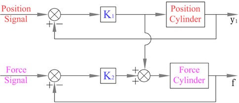
According to Eq. (14), the decoupling process analysis of the input signal is confirmed and completed by the parallel servo system with a dual-electro-hydraulic execution cylinder, so the force/position control mode of the servo cylinders will not affect each other. The principle diagram of the position/force control mode of a parallel system of with double electro-hydraulic cylinders is proposed, as shown in Fig. 6.
Fig. 6Schematic diagram of force/position control parallel cylinders
4. A comprehensive analysis of kinematics/dynamics of the FLHL robot designed for this subject
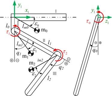
In this subject, the FLHL robot is mainly composed of three mechanical body structures and the joint structure with 12 degrees of freedom, it is emphasized here that the abduction/hip joints intersect at a certain point on each supporting leg, and each liner hydraulic cylinder contains a single rod cylinder block, a servo control valve, a linear displacement sensor and two pressure sensors and other components. The robot support leg uses a spring to absorb the energy of the ground and to release energy during the lifting cycle. Fig. 7 reveals the geometric dimensions of a heavy load hydraulic four-legged robot. Herein, and are expressed as length variables related to the hinge joint coupling links, and describe the related hinge joint angles, and represent the centroid displacement variables of interconnected links, and represent the quality variables of correlation links, and are the connection angles between quality center and related links, and are the torques of corresponding joints.
To the author’s knowledge, the walking frequency of a four-legged robot decreases with the increase of body length and improves with the increase of walking speed. The gait frequency is higher, and then the walking efficiency is lower. The target mass of the four-legged robot developed in this study is no more than 125 kg (total weight), and the target theoretical speed is not less than 1.80 m/s. The optimal gait frequency of the four-legged robot is in the range of 1.0 Hz to 2.0 Hz. The dynamic response frequency of the hydraulic servo cylinder should meet and adapt to the gait frequency requirements.
As far as the authors know, the walking frequency of a four-legged robot decreases with the increase of body length and accelerates with the rapid walking speed. The gait dynamic frequency is higher, and then the walking response efficiency is lower. The target mass of the four-legged robot developed in this paper is no more than 125 kg (total weight), and the target speed is not less than 1.8 m/s. The optimal gait frequency of the four-legged robot is 1.0 Hz to 2.0 Hz. The response frequency of the hydraulic servo cylinder must meet the gait dynamic frequency requirements.
Table 1Main parameter symbols and specification values of the four-legged robot
Parameter symbol | Specification values |
Weight (No external loads) (kg) | ≤ 90 |
Physical dimensions (mm) (Length × Width × Height) | 1200 ×550 × 780 |
DOFs per spring-support leg | 3 (active rotational DOFs) |
Hydraulic actuated pressure (MPa) | 32 |
Main motion posture | Bionic gait |
Optimal gait frequency (Hz) | 1.0-2.0 |
Maximum payload (kg) (On flat ground) | 125 |
Maximum gait walking speed (m/s) (On flat ground) | 2.0 |
Maximum dynamic driving force (KN) (Single servo cylinder) | 5.50 |
4.1. Solving kinematics equations of a FLHL robot
The dynamic stability of a FLHL robot is characterized by its kinematics. Fig. 7 defines the coordinate systems and kinematic vectors. In view of the mechanical structure design forms of the spring-support legs are extremely similar, the four legs coordinate system and the transformation matrix are also similar. The posture of the rear legs and forelegs is the only difference. Referring to the four-legged animals walking posture, the displacement of the four-legged robot is achieved by the force control unit of the support legs. The expression equation at the end of the support leg is revealed as shown in Fig. 7:
According to Eq. (16), the correlation between the displacement of the roller hinge joint actuator and the full-space rotation angle of the hip joints can be expressed as:
Due to the limitations of the structure, the coordinate value of the end of the support leg is .
Fig. 7Geometric dimensions of mechanical structure of hydraulic four-legged robot support leg
The Eq. (16) coordinates value and is identified as:
where the calculations values of and are defined as:
Then the Eq. (17) is rewritten as:
Herein the calculations values of andare expressed as:
Already concerned the comprehensive structural limitations of a heavy load hydraulic four-legged robot studied in this paper, then the expressions and are justified. That is, the Eq. (22) is considered valid. The angle of the joint is solved by the Eq. (16). As mentioned above, the mathematical correlation between the servo actuator displacement vector and full-space angle of the joint is described. Therefore, the specific requirement instruction signal of an electro-hydraulic servo actuator is solved according to the Eq. (16). Because the dynamic gait of spring-support leg is a symmetrical form, the mass properties or inertial indicators of the support legs have little effect on the dynamics of the heavy load robot, since the proportions of the two diagonal legs swinging together are arbitrary, and their dynamic effects almost counteract each other. Hence the quality of torso body in walking posture optimal design is only considered in the study.
4.2. Solving dynamics equations of a FLHL robot
In Fig. 7, from this, the following conclusions are obtained: The kinematic equations are correct and that a FLHL robot has higher kinetic energy and potential energy than a light-loaded robot. On the basis of the above research, the system dynamics Eq. (23) can be obtained from the Lagrangian equation:
where:
The desired planned trajectory is sought through the aforementioned kinematics equations, and the multiple joint torques required can also be obtained by these dynamic equations. In the author’s research topic, the FLHL robot joint of this design is actuated by an electro-hydraulic servo execution cylinder placed at the end of the spring-support legs. It is worth noting that the design according to the variable length of the outrigger of the four-legged robot and the installation positions of the servo execution cylinder on the spring-support legs. Furthermore, the output decoupling of the FLHL robot with force/position hybrid controllable model is described, and the output variable decoupling process of the force/position control hybrid model in the AMESim is implemented.
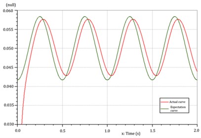
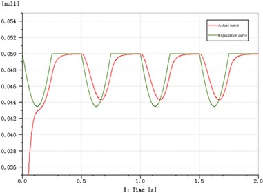
In this chapter, the time domain curves of the required position and physical position are drawn by using the AMEsim software, and the decoupling characteristics of the force/position hybrid control model are realized. Fig. 8 is the time-domain curve of the decoupled slope response of the force/position hybrid control model. In Fig. 9, the time-domain
Fig. 8Curves of slope response decoupling
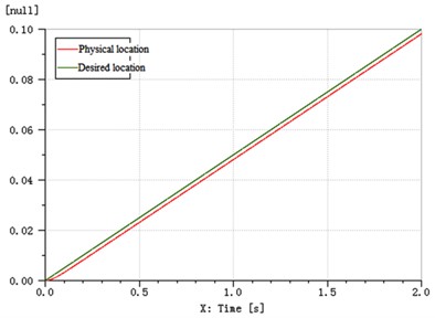
Fig. 9Curves of step response decoupling
4.3. Effect of stiffness variable on synchronization performance of servo controller
In this section, the effects of joint stiffness and system stiffness on the dynamic synchronization characteristics of servo controller are discussed under three typical loads of step load, alternating load and impact load. Among them, the system stiffness 1.80×10⁵ N⋅m/rad, the joint connection stiffness 2.32×10⁷ N⋅m/rad. Fig. 10 shows the influence curves of system stiffness on servo controller synchronization, the influence curves of joint connection stiffness on synchronization of servo controller are shown in Fig. 11.
From the above simulation data, the following conclusions are drawn: the reduction of the objective system stiffness effectively increases the elastic buffer of FLHL robot and is beneficial to its protection; however, the change of joint stiffness has a great influence.
Fig. 10Influence curves of system stiffness on servo controller synchronization: a) variation curves under alternating load, b) variation curves under step load, c) variation curves under impact load
a)
b)
c)
4.4. Optimal design of controller
The PD controller with the position control model is confirmed, in the force control mode, this paper has been proposed a compound strategy with minimum flow/speed compensation and servo control. For details, see the reference [27]. The robotic planning path trajectory generator provides a reference joint angle through the servo controller with PD strategy. Based on the research of this subject, a force control loop is added to deal with the joint force error, and the joint displacement value of the corresponding part is solved. Namely, considering the time-varying disturbance of the joint angle reference value, the system provides the joint force feedback to realize the position tracking of the PD controller. Both the force vector control mode and the position vector control mode are always in the interconnect configuration operation, once the force is wrong and needs to be handled, the connection joint should become compliant. If there is no force error, the force/position control joint tracking is preferred. No matter how the force error changes, the joints of the key parts must guarantee their predetermined rigidity/softness for a long time. The connection modulation strategy between force feedback and active obedience is established friendly.
Fig. 11Curves of joint connection stiffness on synchronization of servo controller: a) variation curves under alternating load, b) variation curves under step load, c) variation curves under impact load
a)
b)
c)
4.5. Calculation model of supporting leg variable damping force
Based on the hybrid mode, the variable damper is the core component of the supporting leg. The damping force is regarded as the sum of multiple driving forces in the supporting legs controls. Herein, assuming that the effective leg diameter of the supporting leg control mode is equal to the diameter of its control valve, the tolerance area is displayed during a specific calculation control process and set equal to the resistance area during actual operation variable . The parameter is used instead of , and a mathematical calculation model for the supporting leg to control the damping force is performed. Its expression is:
From the above discussion, the damping force in the outrigger control is composed of two parts: The first part is related to the dynamic viscosity of lubricating oil, which generally reveals the viscous damping characteristics of the legs in the intelligent control technology. The second part shows that the force is related to the yield strength, which reveals that the yield strength is a quantitative parameter of Coulomb damping characteristics. The above damping force shows an exponential change trend with the control process. The expression of its change multiplier can be written as:
As far as the author knows, the analytical formula used to solve the flow pressure difference in the outrigger control mode is an algebraic equation, which reflects the valve unit force in the damping force control mode and presents the relationship between the external pressure difference and the yield strength. The simplified expression is described as:
where, represents the external excitation load pressure of the control valve, is the transient time-varying stress on supporting leg joints bearing. is the differential pressure of the control valve.
Then, the correlation between the two parameters is:
The correlation time-varying curves between two parameters are shown in Fig. 12.
Fig. 12Correlation time-varying curve between two parameters P0 and T0
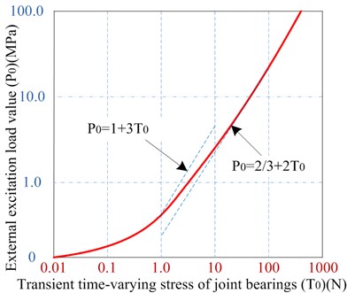
With reference to the general actual environment, the outrigger is in a normal progress state when the value should not be greater than 1.0 (that is ). Only if the mode control speed of the outrigger is lower, the value may not be less than 1.0 (That is, if , then ).
5. Experimental research and results
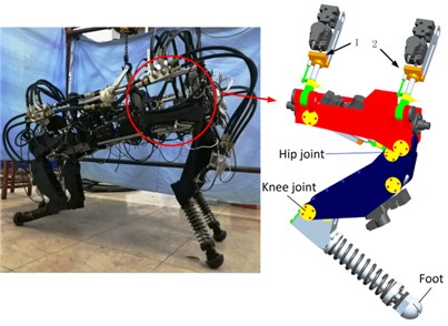
The compound strategy cannot only effectively reduce the internal force, but also enhance the actual driving force. The experimental prototype of this subject is validated on the test platform of the parallel electro-hydraulic servo execution cylinder system. Fig. 13 shows the prototype of the servo actuator with an electro-hydraulic system of four-legged robot.
From the Fig. 13, in the experimental verification process, based on the use of a preset low-pass filter with a lower cut-off frequency of 250 rad/s to further improve and enhance the sensor signal quality, the power supply pressure here is 7.0 MPa.
5.1. Response experiment of position vector unit control mode
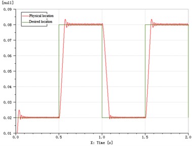
Considering the diagonally extended spatial state of the involved FLHL robot, the movement forms of the two legs on the diagonal are exactly the same and the walking posture transition phase or the support dynamics phase is also in a time-varying period. The controllable method of spatial gait position has the advantages of lower energy loss, fast tempo and relatively stable constant stride in all directions. This gait position control mode has the advantages of low energy loss, fast travel speed, and relatively stable walking posture. The dynamic response curves of hip joint position are shown in Fig. 14.
Fig. 13A four-legged robot with electro-hydraulic servo actuator: 1 – valve assembly, 2 – displacement vector sensor element, 3 – servo control valve with asymmetry, 4 – electro-hydraulic servo execution cylinder, 5 – location marking device, 6 – force vector sensor element, 7 – articulated bearing with full-space rotation performance
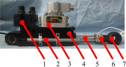
Fig. 14Comparison of dynamic response curves of actual position and expected position of hip joint
a) Dynamic response curves of hip joint
b) Dynamic response curves of knee joint
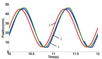
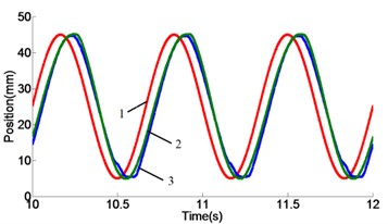
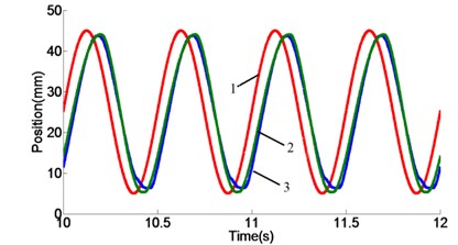
Fig. 15Position response curves at different frequencies: a) response curves of 1.0 Hz, b) response curves of 1.5 Hz, c) response curves of 2.0 Hz
a)
b)
c)
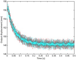
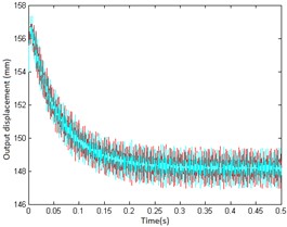
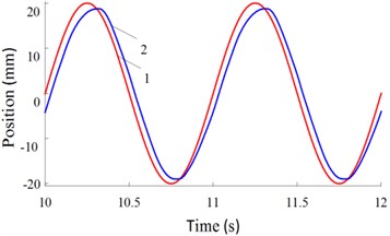
In the study of this paper, the parallel electro-hydraulic servo system has zero-bound damping characteristics, and its steady-state error and speed asymmetry are manifested by the amplitude of attenuation and the asymmetric phase lag. Fig. 15 shows the displacement response curves of 1.0 Hz, 1.5 Hz and 2.0 Hz simulation systems. As shown in Fig. 15, the curves 2 and 3 show that the dynamic response characteristics have too many similarities. Herein the dynamic response curve 1 is indicated in the predetermined input command signal, and the curves 2/3 are the one-to-one designated corresponding position dynamic real-time response curves of the servo cylinders 1/2, respectively.
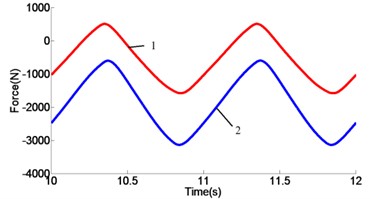
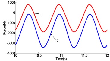
Fig. 16Force curves: a) response curves of 1.0 Hz, b) response curves of 1.5 Hz, c) response curves of 2.0 Hz
a)
b)
c)
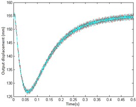
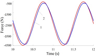
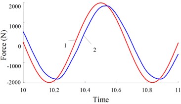
From the Fig. 16, the force response curves of 1.0 Hz, 1.5 Hz and 2.0 Hz systems are revealed. The response curve 1 and the response curve 2 are the corresponding force curves of the cylinder 1 and the cylinder 2, respectively. In Fig. 16, the curves 1/2 have different functions under the dynamic real-time response characteristics of the same position. The dynamic response curve 2 always shows a negative trend, and curve 1 shows a positive and negative equilibrium state. Therefore, if the force value is shown as positive, the output forces of the actuator decrease.
5.2. Experiments for an internal force inhibition
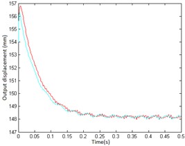
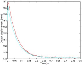
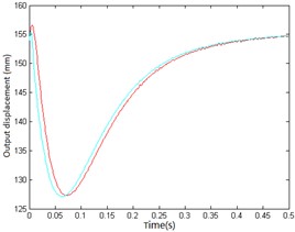
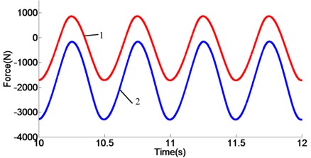
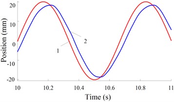
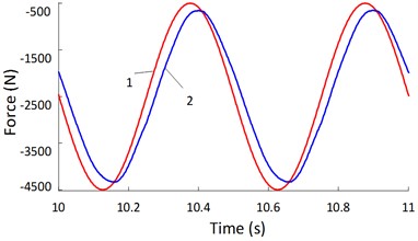
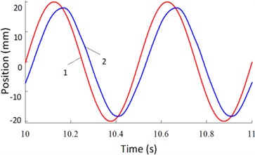
The dynamic response curves of displacement and force variables for 1.0 Hz, 1.5 Hz and 2.0 Hz systems are shown in Figs. 17-19. The graph a) describes the change trend of the dynamic response curve of the driving force of the servo actuating cylinder, the signal amplitude is set to 2000 N. And then the graph b) represents the time-varying law of the dynamic response curve of the displacement of the servo cylinder, here the signal amplitude is set to 20.0 mm. The curve 1 is the design request command signal, and the curve 2 represents the corresponding dynamic real-time response process.
Based on the above relevant research precondition, the results show that under the given demand signal, the parallel double-cylinder hydraulic actuator system designed in this paper has excellent servo tracking capability. Thereby the amplitude reduction and phase lag of the trajectory tracking signal in the dual vectors (force/position) hybrid control modes are close to each other. When the specific command signal frequency is 1.0 Hz, 1.5 Hz and 2.0 Hz, the amplitude attenuation values are 5.52 %, 7.54 % and 8.53 %, and the phase lag values are 9.0°, 13.0° and 18.0°, respectively.
In actual application engineering, the adverse effect of the phase lag can be compensated by the front-feedback servo controller. As the frequency of the external excitation signal increases, furthermore, the amplitude attenuation and phase lag of parallel electro-hydraulic servo system are both increased. The conclusion of this research has proved the effectiveness of a parallel servo cylinder with force/position hybrid control mode.
Fig. 17Real-time response curves of 1.0 Hz: a) real-time change curves of driving force, b) real-time change curves of position
a)
b)
Fig. 18Real-time response curves of 1.5 Hz: a) real-time change curves of driving force, b) real-time change curves of position
a)
b)
Fig. 19Real-time response curves of 2.0 Hz: a) real-time change curves of driving force, b) real-time change curves of position
a)
b)
6. Conclusions
In the author’s research project, a scheme for FLHL robot to reveal motion and dual vectors (force/position) hybrid control modes of a parallel-executed cylinder mechanical integration system has been proposed. First, the preliminary results validate a prototype of a proof-of-concept hydraulic four-legged robot. Then, the simulation results the kinematics and dynamics of the relative force/position controller are analyzed.
1) In view of the larger deadweight load and torsional moment of the supporting and hip joints of a non-lightweight hydraulic servo four-legged robot, a parallel cylinder actuation scheme has been identified to improve the initial active torsional moment.
2) Based on the performances of the parallel-executed cylinder mechanical integration system with dual vectors (force/position) hybrid control modes servo actuator designed in this paper, by optimizing the dual vectors of force signal and position signal, the decoupling analysis process of force/position control mode is realized.
3) The compound optimization strategy is reasonably verified on the simulation platform of the parallel-executed cylinder mechanical integration system. The experimental results show that the dual vectors (force/position) hybrid control modes have excellent dynamic response characteristics, and then the effectiveness of the proposed design scheme and control strategy is verified by using the original sample model.
4) These scientific research results obtained in this paper may be rapidly promoted in many special fields of hybrid control of industrial robot systems in the near future, especially in many fields such as military and aerospace, flexible manufacturing, improved operation and remote control.
In the upcoming studies, it takes into account various optimization conditions and is suitable for the analysis process inverse solution of the attitude or rotation torque in the multi-degree-of-freedom robot’s instantaneous contact with dual vectors (force/position) hybrid control modes. The real-time posture stability of the FLHL robot system has been overcome, and the credible results obtained in this paper will be added to the forthcoming research.
References
-
Wooden David, Malchano Matthew, Blankespoor Kevin Autonomous navigation for BigDog, Proceedings of IEEE International Conference on Robotics and Automation, 2010, p. 4736-4741.
-
Beil J., Marquardt C., Asfour T. Self-aligning exoskeleton hip joint: kinematic design with five revolute, three prismatic and one ball joint. International Conference on Rehabilitation Robotics, IEEE, London, UK, 2017, p. 1349-1355.
-
Semini C., Tsagarakis N. G., Guglielmino E., Focchi M., Cannella F., Caldwell D. G. Design of HyQ-a hydraulically and electrically actuated four-legged robot. Systems Science and Control Engineering, Vol. 225, Issue 6, 2011, p. 831-849.
-
Matta Gómez A., Del Cerro J., Barrientos A. Multi-robot data mapping simulation by using microsoft robotics developer studio. Simulation Modelling Practice and Theory, Vol. 49, 2014, p. 305-319.
-
Sarkar M., Nandy S., Vadali S., Roy S., Shome S. Modelling and simulation of a robust energy efficient AUV controller. Mathematics and Computers in Simulation, Vol. 121, 2016, p. 34-47.
-
Li X., Pan Y., Chen G. Adaptive human–robot interaction control for robots driven by series elastic actuators. IEEE Transactions on Robotics, Vol. 33, Issue 1, 2017, p. 169-182.
-
Bazeille S., Barasuol V., Focchi M. Four-legged robot legting over irregular terrain assisted by stereo-vision. Intelligent Service Robotics, Vol. 7, Issue 2, 2014, p. 67-77.
-
Hamza Khan, Satoshi Kitano, Marco Frigerio Development of the lightweight hydraulic four-legged robot-MiniHyQ. IEEE International Conference on Technologies for Practical Robot Applications, 2015.
-
Claudio Semini, Jake Goldsmith, Diego Manfredi Additive manufacturing for agile legged robots with hydraulic actuation. Proceedings of the 17th International Conference on Advanced Robotics, 2015, p. 123-129.
-
Bazeille S., Barasuol V., Focchi M., Havoutis I. Vision enhanced reactive locomotion control for legting on rough terrain. IEEE Conference on Technologies for Practical Robot Applications, 2013.
-
Tian X., Gao F., Qi C., Chen X., Zhang D. External disturbance identification of a four-legged robot with parallel–serial leg structure. International Journal of Mechanics and Materials in Design, Vol. 12, Issue 1, 2016, p. 109-120.
-
Xianbao Chen, Feng Gao, Chenkun Qi Spring parameters design to increase the loading capability of a hydraulic four-legged robot. International Conference on Advanced Mechatronic Systems, 2013, p. 535-540.
-
Mantian Li, Zhenyu Jiang, Pengfei Wang Control of a four-legged robot with bionic springy legs in legting gait. Journal of Bionic Engineering, Vol. 11, Issue 2, 2014, p. 188-198.
-
Gonzalez Luchena I., Gonzalez Rodriguez A.-G., Gonzalez Rodriguez A. A new algorithm to maintain lateral stabilization during the running gait of a four-legged robot. Robotics and Autonomous Systems, Vol. 83, 2016, p. 57-72.
-
Gorp Pathak M. M. M., Samantaray A. K. Fault accommodation in compliant four-legged robot through a moving appendage mechanism. Mechanism and Machine Theory, Vol. 121, 2018, p. 228-244.
-
Amanuel T., Ma J. G. Modeling and simulations on a fuzzy-PID position controller of electro hydraulic servo system. 12th International Conference on Fuzzy Systems and Knowledge Discovery, FSKD, 2015, p. 96-103.
-
Gehring C., Bellicoso C. D., Coros S., Bloesch M., Fankhauser P., Hutter M., Siegwart R. Dynamic legting on slopes for four-leggedal robots. IEEE/RSJ International Conference on Intelligent Robots and Systems, Hamburg, Germany, 2015, p. 5129-5135.
-
Zhen W. K., Kang X., Zhang X. S., Dai J. S. Gait planning of a novel metamorphic four-legged robot. Journal of Mechanical Engineering, Vol. 11, 2016, p. 26-33, (in Chinese).
-
Zhang C., Dai J. S. Continuous static gait with twisting trunk of a metamorphic four-legged robot. Mechanical Sciences, Vol. 9, 2018, p. 1-14.
-
Xin Y., Liu B., Rong X., Li B., Wang H. Research on smooth leg-to-walk gait transition algorithm for four-legged robot. IEEE Chinese Automation Congress, 2017, p. 5967-5971.
-
Liu W., Zhou L., Qian H., Xu Y. Turning strategy analysis based on leg gait of a four-legged robot. IEEE International Conference on Robotics and Biomimetics, 2017, p. 1306-1311.
-
Zhang C., Wang X., Wang X., Dai J. S. Modeling for a metamorphic four-legged robot with a twisting trunk: Kinematic and workspace. IECON 43rd Annual Conference on Industrial Electronics Society, Beijing, China, 2017, p. 6886-6892.
-
Wang Z. W., Duan R. Z., Sun G. T. Hydraulic four-legged robot joint force control based on double internal model controller. International Journal of Control and Automation, Vol. 9, Issue 1, 2016, p. 241-250.
-
Shao J. P., Mu X. N., Sun G. T., Yang W. Y. Joint torque control of hydraulic four-legged robot. International Journal of Control and Automation, Vol. 8, Issue 5, 2015, p. 383-390.
-
Gong D. W., Wang P., Zhao S. Y. Bionic four-legged robot dynamic gait control strategy based on twenty degrees of freedom. IEEE-CAA Journal of Automatica Sinica, Vol. 5, Issue 1, 2018, p. 382-388.
-
Zhang T. H., An H. L., Ma H. X. Joint torque and velocity optimization for a redundant leg of four-legged robot. International Journal of Advanced Robotic Systems, Vol. 14, Issue 5, 2017, https://doi.org/10.1177/1729881417731897.
-
Ba K. X., Yu B., Kong X. D. The dynamic compliance and its compensation control research of the highly integrated valve-controlled cylinder position control system. International Journal of Control Automation and Systems, Vol. 15, Issue 4, 2017, p. 1814-1825.
About this article

The authors would like to thank the Northeast Forestry University (NEFU), Heilongjiang Institute of Technology (HLJIT), and the Harbin Institute of Technology (HIT) for their support.
The research topic was supported by the Doctoral Research Startup Foundation Project of Heilongjiang Institute of Technology (Grant No. 2020BJ06, Yongmei Wang, HLJIT), the Natural Science Foundation Project of Heilongjiang Province (Grant No. LH2019E114, Baixue Fu, HLJIT), the Basic Scientific Research Business Expenses (Innovation Team Category) Project of Heilongjiang Institute of Engineering (Grant No. 2020CX02, Baixue Fu, HLJIT), and the Special Project for Double First-Class-Cultivation of Innovative Talents (Grant No. 000/41113102, Jiafu Ruan, NEFU).
