Abstract
Paper presents a part of research concerning freight cars modernization. The main causes of damage of freight cars plating are chemical interactions of the carried material and the car body as well as mechanical damages. The introduced structural change consists in the use of composite panels to protect the steel plating of a car body. Therefore, it is necessary to carry out a series of studies. In this paper results of virtual simulations of the freight car vibration during its motion as well as verification of a possibility to create a method to verify technical condition of the freight car during its exploitation based on excited vibrations are presented.
1. Introduction
The presented work is continuation of a previous research project concerned with modernization of freight cars using new, non-classical materials. The proposed solution for modernization of freight cars shells was to use composite materials connected to old elements made of steel. In this research project the scope of works is wider. Not only tasks concerned with use of new materials in freight cars are considered. Effects that are to be achieved by the modernization are better corrosion protection of the freight car elements, easier unloading of the freight car in winter conditions (no freezing of the cargo to the floor and sides), reduction of the freight car’s weight while its payload increases, easier management of the freight wagons during exploitation, application of non-destructive testing methods to verify technical condition of the freight car during its exploitation.
In this work the last of mentioned goals of the research project is presented. The aim of these authors’ research is to determine the possibility of identifying the technical state of the modernized freight wagon based on continuous measurement of the dynamic response during operation. The idea is to create a system integrated with elements of the modernized wagon body shell and for generating alarm signals that will be able to be read periodically by the service, or sent directly after the occurrence, using a wireless system. As sensors piezoelectric transducers in the form of films will be used. They will be integrated with elements of the modernized wagon shell [1].
Issues related to the study of the dynamic response of both railway rolling stock and railway infrastructure are the subject undertaken by a number of research centres. Dynamic loads generated during the passage of railway trains are deleterious to the infrastructure, such as bridges or buildings located near tracks, as well as people staying in them. There is however the possibility of their use in systems for condition monitoring of infrastructure components [2-4]. Due to the dynamic loads generated by moving with higher and higher speed of trains, in the face of aging and worn out infrastructure, these issues are now becoming extremely important. In recent years it can be noticed that significantly increase interest in this subject, as well as the increase in the number of performed acceptance tests of objects under dynamic loading. This is the result of activities related to the implementation of the program of modernization of railway lines in Poland and the introduction of high-speed rail, so passenger transport at speeds above 200 km/h. These issues are discussed among others in the works [2, 3], regarding the dynamic impact of high-speed trains on railway bridges and viaducts, as well as acceptance testing of such facilities under dynamic loading test. Also important are issues of protection of building against vibration generated by the ground and underground rail communication as well as protection and minimize the impact of vibrations on both the passengers and persons in the buildings surrounding the railway line [4].
2. Analysis of motion of a freight car in an advanced engineering environment
The introduction of various modifications in constructional solutions of the existing technical means, which aim is to improve their chosen properties, requires every time additional tests. In this study is considered the technical mean, which is a dumping freight car of the 418V type (Fig. 1). The idea of simple virtual test of this wagon has been presented in [5]. But the requirements considered with higher fidelity of the model test has caused that to the previous model haven been applied elastic and elastic-damping components raising the reality of obtained results. The first step of investigations of the freight wagon was to create a model prepared for motion simulation. For this purpose was used the “Motion Simulation” module of the system of the CAD/CAE/CAM class (Siemens PLM NX). The model, prepared to motion simulation, was created on the basis of a solid model, which imitates the geometrical form of the 418V dumping, freight wagon.
Obtained results of the analysis, on the basis of visual evaluation of derailing of the freight car, let to eliminate the ranges of speed values above which explicitly come to wagon derailment from the track. However, with regard to the positive results of the simulation it should be examined the level of safety of the wagon movement on the track in the form of an arc. Accordingly, in the work is assumed that in the cases in which there has been no explicit derailment, it should be calculated the index of derailment danger, shown in [6-8]. The authors of these works suggest that the safety of wagon movement on the track is dependent on the relationship of forces (Fig. 2). Where force is described as a lateral, guiding one and the force is described as the force of a vertical pressure of a wheel on the rail. Due to the geometry of the rail head and existing components of friction forces between the wheel and the rail head, it is assumed that the movement of the wagon along the track is safe if the ratio 0.78. Whereas this value is exceeded, it should be checked the vertical displacement of the wagon wheel, which should not be greater than 5 mm. Obtained values of the derailment index of the wagon at the speed equal to 77 km/h are presented in Fig. 1.
Fig. 1Values of the derailment index of the wagon at the speed equal to 77 km/h
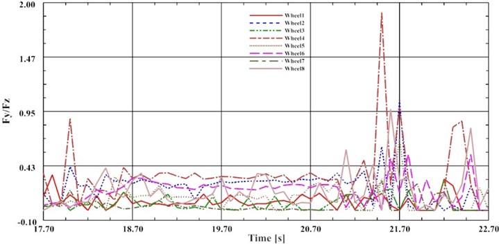
The value of this index is greater than the limit value. When the speed increased to 77 km/h maximal value of the ratio has increased to approx. 1.9. On the basis of the two criteria it could be assumed that the maximal safe speed value at which moves the investigated wagon with the cargo, on the arc-shaped track, is 77 km/h. It should be noted however that in the case of analyzing the movement of a wagon moving at high velocities, besides to the phenomenon of climbing the wagon wheel on the rail head is also dangerous the phenomenon of detachment of the wheels of the wagon moving on the inner rail due to the occurrence of a centrifugal force. Therefore, in the work it was decided to examine the course of the value of the force pressing the wagon to the rail. If the value of this force is equal to zero then the vertical movement of the wheels should be checked. Results of those analyses will be presented in other publications.
The next phase of the work included operations aimed the detailing of the virtual model of the wagon movement on the track way. For this purpose, the model prepared for motion simulation was complemented with the elastic elements. The introduced change forced also the remodelling of the model. In the analyzed model was adopted an elastic element with a line characteristic:
where: – stiffness 1×10⁷ N/m, , – displacements of the ends of the spring as a function of time.
An example of obtained results is presented in Fig. 2. Displacements of wheels in the vertical axis during the wagon movement on the arc part of the railway at the speed equal to 77 km//h are presented when the model includes elastic elements.
Fig. 2Displacements of wheels in the vertical axis during the wagon movement on the arc part of the railway at the speed equal to 77 km//h (the model includes elastic elements)
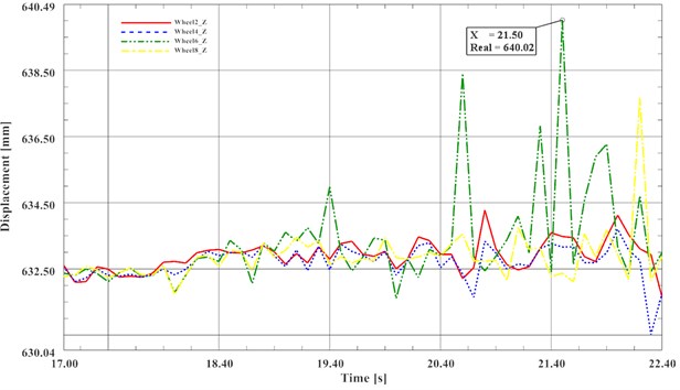
The presented values of displacement of the wagon wheels exceed the required threshold of safety value equal to 5 mm. In order to mapping better the behaviour of the wagon during its motion on the railway the elaborated model has been further refined. Another providing of the model with details consisted of implementing a simplified model of friction in the suspension of wagon cars. It was assumed that the friction in the suspension of the car is a viscous one. Damping force is described in this case, with the linear equation:
where is a viscous damping coefficient, , are displacement velocities of damper ends as the function of time. The CAD model with dumping elements is presented in Fig. 3. Results obtained for the model with elastic-dumping elements are presented in Fig. 4.
Fig. 3Introduction of elastic elements to the virtual model
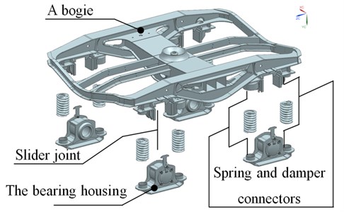
Fig. 4Displacements of wheels in the vertical axis during the wagon movement on the arc part of the railway at the speed equal to 77 km//h (the model includes elastic elements)

3. A real object measurements and laboratory tests
Measurements of the freight car’s elements vibration during operation were also carried out. Measurements were carried out using analogue input cards and portable device NI cDAQ-9191 – the compact 1-Slot chassis which allows send data to a host PC over Ethernet or IEEE 802.11 Wi-Fi. The M-8514-P1 model of Macro Fiber Composite transducers were used as sensors. Four sensors were glued on the surface of the frame and body shell of the tested wagon and connected to the portable measurement system for data acquisition. Measurements were carried out while the observed train was driving (locomotive and two wagons) with the maximum travelling speed about 10 km/h. The train was driving a section of about 400 meters, stopped and then it was returning. The test was repeated five times to verify the repeatability of the results. Measurement points were selected as:
– Channel 1 – the center of the top envelope of the box, interior of the freight wagon;
– Channel 2 – the support frame – the bottom surface of the main, outer beam;
– Channel 3 – the support frame – the inner surface of the main, outer beam of the frame;
– Channel 3 – the support frame – side surface of the crossbeam.
The main aim of the measurements was to acquire a profile of excitations that are elements of the freight wagon exposed to during standard exploitation of the wagon [9]. This profile was in the next step used in tests using laboratory stands in order to verify their dynamical response onto the excitation occurring during standard operation. It was observed that the electric voltage generated by the piezoelectric MFC sensors has not a high value but measured signal can be used in order to reproduce the extortion profile course during laboratory tests. The carried out measurements proved that results are repetitive and can be used in laboratory tests. During all measurements it was observed that obtained results are repeatable (taking into account the range of possible measurement errors) for all tested measuring points without influence of the weather conditions and temperature.
Measured profiles of vibration excitation that are results of the standard operation of the freight car were used for tests on a created laboratory stand. In carried out measurements the laboratory stand was a piece of the freight car’s side created in the scale 1:2. Composite panels were mounted to the freight car’s side model using rivet nuts. During measurements the freight car’s side was excited using vibration test system produced by TIRA GmbH. Macro Fiber Composite M-8514-P1 piezoelectric transducers were used as sensors glued to the surface of the tested elements. Measurements were carried out with and without composite panels mounted to the freight car’s side. The aim of this work was to verify if it is possible to detect the presence of composite panels mounted to the tested freight car’s side element. The tested element was excited using electrodynamic shaker and vibration profile obtained during the measurements carried out on the real freight car was used for excitation. Vibrations of the analysed freight car’s side were measured in four measuring points. MFC sensors were glued to the surfaces of the side’s frame as well as to the sheet metal elements.
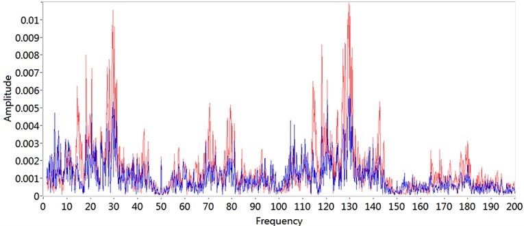
As the next step of the carried out analysis the Fast Fourier Transform of measured signals was carried out in order to verify if any change in the obtained results can be observed. Results of the FFT analysis of measured signals obtained for the system with and without composite panels are juxtaposed in Fig. 6 up to frequency 200 Hz.
Fig. 6An example of results of the FFT analysis of measured signals juxtaposed for the system witch (the blue line) and without (the red line) composite panels
4. Conclusions
As the result of conducted investigations using CAD models it was obtained the value of the safe speed movement of a freight car transported a cargo equal to 77 km/h. The simplification, used in the work, in the form of the lack of a track way slope allows assumes that the adopted model provides a margin of the safe speeds. As the result of the model detailing lower values of vertical displacements of the freight car’s wheels were obtained, at the same speed of movement of the wagon on the track in the form of an arc. On the other hand excited vibration can be used in the system for non-destructive testing method to verify technical condition of the freight car during its exploitation. In order to obtain a proper fit of operation of the virtual model to the real object the research aimed at identifying the real object properties should be continued. Carried out tests and measurements on freight cars as well as using laboratory stands proved that Mecro Fiber Composite piezoelectric transducers can be successfully used as sensors for measurements of freight car’s elements vibrations. They can be easily applied to the surface of monitoring structure as well as laminated in composite panels that will be used during freight cars modernization.
In further research more measurements on laboratory stands and especially on real objects during their exploitation will be carried out in order to obtain a better fit of operation of the virtual model to the real object and verify repeatability of obtained results. It is also important to take into account influence of various conditions such as weather conditions, deformations of the wagon’s body shell that are results of its exploitation, mainly unloading using excavators etc. The influence of changes in monitored system created during its exploitation appears as a main problem which may result in system malfunction.
References
-
Wróbel A., Płaczek M., Buchacz A., Majzner M. Study of mechanical properties and computer simulation of composite materials reinforced by metal. International Journal of Materials and Product Technology, Vol. 50, Issues 3-4, 2015, p. 259-275.
-
Herwig A., Bruhwiler E. In-situ dynamic behaviour of a railway bridge girder under fatigue causing traffic loading. Proceedings of the 11th International Conference on Applications of Statistics and Probability in Civil Engineering, ICASP11, Zurich, Switzerland, 2011, p. 389-395.
-
Oleszak P., Cieśla J., Szaniec W. Study of the effects of side impacts on railway viaduct lying on the arc. Budownictwo i Architektura, Vol. 12, Issue 2, 2013, p. 47-54, (in Polish).
-
Stypuła K. Selected problems of surface building protection against vibrations generated by underground communication. Górnictwo i Geoinżynieria, Vol. 3, Issue 1, 2009, p. 351-362, (in Polish).
-
Buchacz A., Baier A., Herbuś K., Majzner M., Ociepka P. Investigation of motion of a freight wagon aimed to identify the forces acting on the side wall of the wagon. Dynamical Systems: Mechatronics and Life Sciences, ARSA Łódź, 2015, p. 77-88.
-
Matej J. Simulation method of assessing the level of risk of derailment of the freight wagon on straight track. Przegląd Mechaniczny, Vol. 1, 2011, p. 20-25, (in Polish).
-
Matej J. Modeling and Simulation Research of Bimodal Wagons in Terms of Risk of Derailment. Scientific Works: Mechanics, Publishing House of Warsaw University of Technology, Vol. 234, 2010, (in Polish).
-
Dusza M., Zboiński K. Accurate determination of critical velocity of rail vehicle model – comparison of methods. Technical Magazine: Mechanics, Vol. 109, Issue 14, 2012, p. 71-80, (in Polish).
-
Płaczek M., Buchacz A., Wróbel A. Use of piezoelectric foils as tools for structural health monitoring of freight cars during exploitation. Eksploatacja i Niezawodnosc – Maintenance and Reliability, Vol. 17, Issue 3, 2015, p. 443-449.
About this article

The work was carried out under the Project Number PBS2/A6/17/2013 funded by the National Centre for Research and Development.
