Abstract
The pentadecane single droplet size of less than 20 µm and its refractive index were measured at various ambient temperatures of 100, 120, 150 and 180 °C. The experimental setup was equipped with the high speed linear CCD camera to give sharp and clearly visible MDRs (Morphology Dependent Resonances) structure from the droplet refractive index. The valve of the heated chamber was closed during the experiment until the droplet disappeared from the chamber to increase the measurement time of about 2 folds in order to obtain more experimental data of the droplet behaviors. The cooling device was mounted on the heated chamber to improve boundary condition and smooth the ambient temperature. The obtained droplet sizes were in good agreement with both the D2 law and the Rapid Mixing Model (RMM), while the measured droplet refractive index values were closed to those calculated from the previous reported formula. This has indicated the reliability and applicability of this improved measurement technique for a better understanding of the real fuel droplet behaviors in a combustion system.
1. Introduction
Fuel in the combustion chamber contains millions of droplets. The fuel droplet behaviors including size and refractive index are important parameters for the evaluation of the characteristics and behaviors of fuel droplets in a combustion chamber. Various droplet behaviors have been investigated such as evaporation by Wilms [1], size by Glover et al. [2], temperature by Castanet et al. [3, 4] and refractive index and rainbow angle (for refractive index determination) by Roth et al. [5, 6] and Anders et al. [7]. In addition, droplet temperatures and droplet fractions of the components inside the droplet as in the case of multi-component droplets can be determined from the measured refractive index value. Numerous techniques have been adapted to examine the single droplet characteristics and behaviors including MSI (Mie Scattering Imaging) by Wilms [1], Laser Imaging for Droplet Sizing (ILIDS) by Glover et al. [2], Kobayashi et al. [8] and Kawaguchi et al. [9], Phase Doppler Anemometry (PDA) by Fieberg et al. [10], Sangkaew [11] and Fandrey et al. [12]. Not only the experimental method can be used to investigate the droplet behaviors, but also the numerical calculations [13] or both the experimental and numerical calculations as well [8].
Glover et al. [2] have performed on the large droplet size in several millimeters to several hundred millimeters using the angular intensity oscillations in the wide-angle forward-scatter region method, which are not suitable for the interpretation of the real fuel droplet condition in the combustion chamber in which the droplet size is in the micron scale (10-240 µm) [14]. This gave the insufficient information for an accurate evaluation of the fuel droplet size in the real system. Groups of fuel droplets in the form of spray which cannot be used to determine accurately the individual fuel droplet characteristics have also reported [8]. Behaviors of many droplets presented as an average value were also not the real presentation of the only one droplet behaviors [3]. Honnery et al. [13] have examined the behaviors of small droplet size (of less than 100 µm) and velocity measured by the Magnified Digital In-line Holographic Particle Image Velocimetry (MDIH-PIV) technique with a HeNe laser, but have not measured the refractive index. The droplet refractive index was measured at low frequency with low speed camera resulting of not being able to obtain the clearly visible MDRs (Morphology Dependent Resonances) [1]. In order to obtain the MDRs that can be used to determine changes of the droplet diameter from the droplet refractive index, the frequency of the measurement should be sufficiently high. In addition, it has been reported that the measurement time of the droplet size and refractive index must be long enough in order to get sufficient information for the droplet behavior evaluation [13].
Therefore, the objective of this present study was to develop an improved size and refractive index measurement technique of a small single droplet (20-40 µm) of a model liquid, pentadecane in a heated chamber. This technique included the combining of a high speed linear CCD camera for the high frequency measurement and the proper closing valve period of the heated chamber to increase the measurement time with the cooling device to improve the boundary condition and using the Mie Scattering Imaging and Rainbow Refractometry technique to determine the droplet diameter and refractive index. The experimental results were also compared with the two numerical models. This improved measurement technique can get more reliable and accurate droplet behavior information which will be certainly beneficial for the evaluation and anticipation of the fuel droplet behaviors in a real engine system.
2. Materials and Methods
2.1. Experimental equipment
The experimental equipment consisted of a heated chamber, a linear CCD camera, a laser, a cooling device, a droplet on demand generator, the Position Sensing Diode (PSD) and the temperature profile measurement system (traverse and thermocouple).
2.1.1. The heated chamber
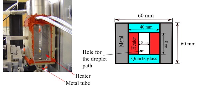
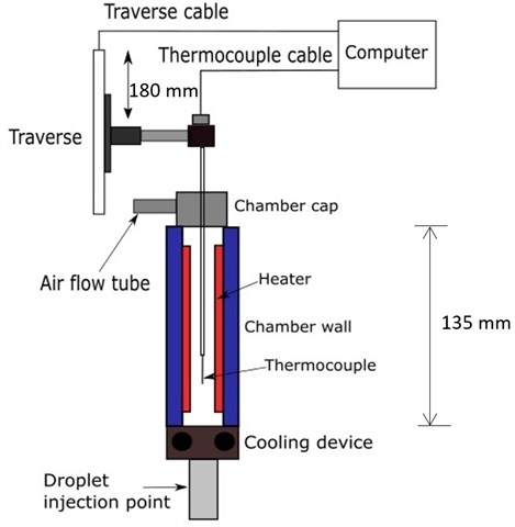
The length of the chamber was 13.5 cm. Two opposite sides of the chamber were made of quartz glass in order to allow observation of the droplet. The other side was made of copper containing an electrical heater. The outer cross section of the heated chamber for the droplet path was 6×6 cm2 and the inner cross section was 4×4 cm2. Fig. 1 displayed the heated chamber without the cooling device and showed a schematic of the top view of the heated chamber.
Fig. 1The heated chamber without the cooling device and schematic top view of the heated chamber
2.1.2. The linear CCD camera
The two cameras were the high speed cameras (Atmel and Aviiva model AT71YM2CL2013-BA6) for measuring the droplet diameter at the forward region (Atmel) with the frequency of 5,000 fps (frames per second) and the refractive index at the backward region (Aviiva) of 12,500 fps.
2.1.3. The laser
It was at the wavelength of 532 nm. The laser model was FYPL-0532-500T and manufactured by Frankfurt Laser Company, Germany.
2.1.4. The cooling device
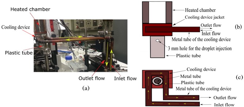
The cooling device was shown in Fig. 2. It was mounted over the metal tube below the heated chamber. The tube of the cooling device was made of metal. Water at room temperature (27±3 °C) was used as a cooling fluid. It entered the experimental setup from the left tube (inlet flow), then reached the metal tube below the heated chamber and circulated. After that, the water flowed from the experimental setup through the right tube (outlet flow) into the sink. At the circulation region below the heated chamber, there was a jacket covering the metal tube of the cooling device.
Fig. 2a) The cooling device and the heated chamber, b) schematic side view of the cooling device, c) schematic top view of the cooling device
2.1.5. The droplet generator
The pentadecane (Fluka Chemica Company, Switzerland) was used as a hydrocarbon liquid. The pentadecane single droplets were generated by the droplet generator (Fig. 3) which was an electrical generator. It consisted of a metal tube that compressed and decompressed the liquid column as shown in Fig. 4. The generator was driven by an electrical pulse generator. The voltage frequency and amplitude were changed to adjust the droplet flow. Orifices with a diameter of 40 µm were used. The resulting initial droplet sizes ranged from the orifice diameter to 1.2 times of the orifice diameter.
2.1.6. The temperature profile measurement system
The temperature profiles in the heated chamber were measured by a temperature measurement system consisted of the thermocouple and the traverse shown in Fig. 5. The traverse was controlled by a computer. The temperature measurement started at the droplet injection position. Length of the temperature profile measurement was 180 mm (the length of the chamber was 135 mm, but the system also measured the position which was out of the measurement range). The measurement was measured at every 2 mm. The traverse started to move from position 0 to 4, 8, 12,... up to 180 mm, then moved back until the position of 2 mm. The thermocouple remained at each position for 2 minutes to reach the equilibrium conditions before performing the temperature profile measurement.
Fig. 3The droplet generator
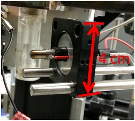
Fig. 4Schematic view of the droplet generator
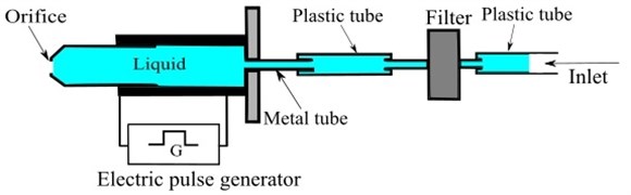
Fig. 5The temperature profile measurement system
2.2. Experimental method
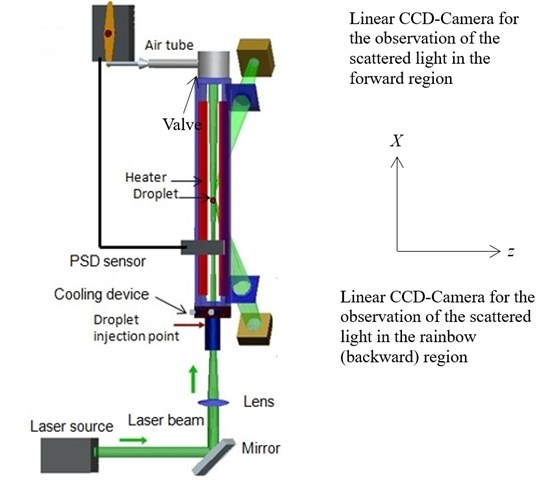
The setup of the heated chamber equipped with a linear CCD camera, a cooling device and a laser was shown in Fig. 6. The pentadecane liquid was injected horizontally along the -axis to form the single droplets and the droplets were decelerated very soon. In the chamber, a vertical upward stream existed due to the chimney effect which transported the droplets along the -axes upwards in a region of the chamber with approximately constant temperature. The droplets were illuminated permanently by the laser beam. As soon as the droplets reached this region, the position was detected by a Position Sensing Diode (PSD) together with the partly closing of the valve at the exit of the flow path to reduce the air velocity in order to keep the droplets as long as possible in the region with approximately constant temperature. The PSD detected the light scattering signal from the droplet and the signal was sent from PSD to the servo motor to close the valve of the heated chamber to have the longer measurement time. At the same time, the equipped high speed linear CCD camera captured the scattered light from the droplet.
Fig. 6The experimental setup
3. Results and discussion
3.1. Effects of the cooling device on the temperature profile
Fig. 7 showed the temperature profile with and without adding the cooling device at a heater temperature of 180°C. Without installing the cooling device, the rate of the temperature change was not smooth. When the cooling device was mounted at the bottom of the chamber (shown in Fig. 6), the rate of the temperature change turned out to be much more gradual. An increase of the ambient temperatures in the heated chamber appeared to be delayed by the cooling device. The temperature was decreased suddenly when the droplets were passing the cooling device. The temperature profile and boundary condition were smooth in which the droplet behaviors were not complicate for the analysis.
3.2. Comparison of the temperature profile at various heater temperatures in the heated chamber with the cooling device
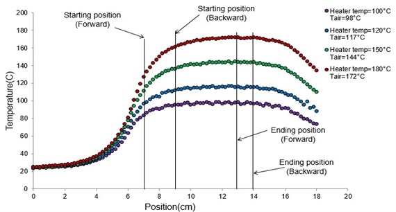
Honnery et al. [13] measured the droplet evaporation under increasing ambient temperatures without the cooling device. The resulting temperature profiles were not smooth, thereby causing the complicated analysis. For the temperature profile measurement in this present study, four heater temperatures were used (100, 120, 150 and 180 °C). The cooling device was added in every case to improve the boundary condition. The temperature profile and the measurement starting point were shown in Fig. 8. The temperature profiles of all heater temperatures with the cooling device gave the same smooth trend. The air temperature (Tair) value in the parenthesis indicated the highest temperature of each profile. The air temperatures were less than the heater temperatures due to the heat loss during the heat transfer from the heater to the air in the chamber. These temperature profiles were used as ambient temperatures for the measurement of the droplet diameter and refractive index.
Fig. 7Temperature profiles with and without the cooling device at the heater temperature of 180 °C
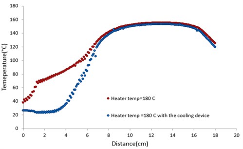
Fig. 8Temperature profiles with the cooling device at the heater temperatures of 100, 120, 150 and 180 °C
3.3. Effects of various ambient temperatures on the rate of droplet diameter changes
Honnery et al. [13] have measured the droplet diameter versus time under an increasing ambient temperatures with the unsmooth temperature profile. They have investigated the droplet evaporation in 3 phases including the preheating phase, the transitional heating phase and the steady evaporation phase. The results showed that while the evaporation rates at the peak temperature condition were generally well predicted, but during the prolonged expansion phase, the evaporation rates were over predicted, and during the transitional heating phase, the rates were under predicted. This was similar to a steady state evaporation process. The experimental evaporation rates were found to be almost linear depending on the gas temperature once the evaporation dominated the expansion processes. For this present work, the droplets were measured in a smooth temperature profile at constant ambient temperatures. The droplet was injected at the position 0 mm (according to Fig. 6). But, the measurement started at the position of 80 mm for the forward scattering region. The backward scattering region started slightly later at the position of 90 mm. This was caused by the thickness of the chamber walls. Fig. 9 displayed the plot of the pentadecane single droplet diameters versus time (in seconds) at various ambient temperatures. The droplet diameters in every case decreased due to evaporation. The rate of droplet diameter changes increased with increased ambient temperatures. The slope of the droplet surface plot increased with increased heater temperatures. The evaporation rate was determined from the slope of the plot between the droplet surface area (non-dimensional) and shown in Fig. 10 [1]. The evaporation rate of the droplet increased with an increase of the slope. This indicated a faster evaporation of the droplets with increasing ambient temperatures. The linear trends indicated a constant evaporation rate. In comparing the result (data not shown) with and without the adjustment of the closing valve period, the measurement time with closing valve was longer than that without closing valve of about 2 times, thereby being able to measure the droplet diameter until the detectable minimum size of 20 µm was disappeared from the chamber. Instead, if the valve was not closed properly, the droplet would leave the chamber rapidly and the minimal droplet size of 20 µm could not be detected. Thus, the technique of adjusting the closing valve period together with the cooling device can increase the droplet size measuring time.
Fig. 9Pentadecane single droplet diameter (µm) versus time (seconds) at various ambient temperatures
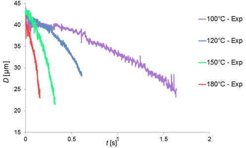
Fig. 10Pentadecane single droplet surface versus t/D02 at various ambient temperatures in comparing with the D2 law and RMM model
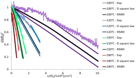
The experimental data were also compared with the law and the RMM models (Rapid Mixing Model or the Infinite Conduction Model). The differences between the law and the RMM model was quite small because of the small change in the droplet temperature due to the small change of the ambient temperatures. There was also a small discrepancy due to the measurement uncertainty, and also the vapor in the heated chamber prevented the evaporation. The experimental results and both the law and RMM models were in good agreement especially the results in the case of higher heater temperatures at 150 and 180 °C and at the constant evaporation rate region (constant slope of the droplet surface plot in Fig. 10). But, high discrepancies were observed at lower heater temperatures of 100 and 120 °C. This may be due to the reaching of the droplet saturation at the beginning of the experiment. When the ambient temperatures decreased, more effects of droplet saturation were observed. The RMM model gave slight better agreement than the law model. For the work of Wilms [1], the droplet size was measured with a low speed camera. Although the experimental results were in good agreement with the numerical model, there were very few data obtained and the minimal size of the droplet diameter measurement was at 40 µm which was bigger than that of our study (20 µm). This result has indicated the more efficient measurement of our improved technique.
3.4. Effects of various heater temperatures on the droplet rainbow position measurement
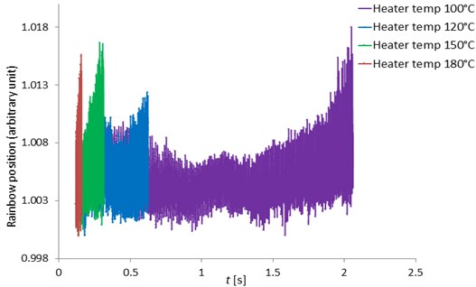
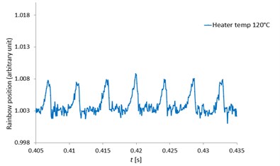
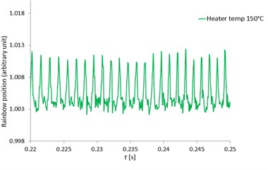
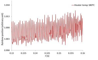
Fig. 11 showed the pentadecane droplet rainbow position versus time (in seconds) at the heater temperatures of 100, 120, 150 and 180 °C. The rainbow position was in arbitrary units because it was derived from the main rainbow position (in angle units) divided by the minimum main rainbow position (in angle units) at each heater temperature. Refractive index can be calculated from the droplet rainbow position because they are the function of the rainbow position. There were fluctuations on the rainbow position caused by MDRs. The refractive index values determined from the rainbow position in this study were close to the refractive index value calculated by the formula of Wilms [1]. The difference was less than 10 %.
Fig. 12 indicated the rainbow position at the heater temperatures of 100, 120, 150 and 180 °C respectively zoomed from the rainbow position of Fig. 11. With high speed measurement using the high-speed camera, the MDRs were sharp and clearly seen at all heater temperatures and the rainbow position mean values were quite constant. The MDRs peaks increased with increased ambient temperatures due to the increase of the evaporation rate. When the MDRs were clearly observed, the droplet diameter changes () and the droplet temperatures can be accurately determined. For the work of Wilms [1], the droplet refractive index were measured with a low speed camera and the MDRs structure was not observed due to the low frequency measurement and also the error from the signal processing. Thus, this developed measurement technique can obtain the accurate and clearly observed MDRs for more droplet behavior information.
Fig. 11The pentadecane single droplet rainbow position as a function of time (second) at various heater temperatures
The measured diameter change () was obtained from the peak of MDRs from the refractive index showing in arbitrary units in Figs. 11 and 12. The diameter changes between the data from the forward region and backward region were in good agreement (data not shown). This confirmed the reliability of the refractive index measurement.
For the further study to improve the experimental results, the measurement can start at the droplet injection point (at the beginning of the temperature profile measurement region) by modifying the chamber. The observation range can also be increased by using more cameras or using a lens which can increase the observation range. In addition, there are two other possibilities. First, it is interesting to investigate the droplet characteristics and behaviors at temperatures which are closer to the real temperature conditions in a combustion chamber that would certainly be more applicable for the real system. Second, a heatable droplet generator could be used to heat the droplet before entering the heated chamber to investigate the droplet heat transfer at the constant droplet temperature.
Fig. 12The zoomed pentadecane single droplet rainbow position as a function of time (seconds) with clearly seen MDRs at the heater temperatures of 100, 120, 150 and 180 °C
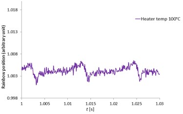
a) 100 °C
b) 120 °C
c) 150 °C
d) 180 °C
4. Conclusions
This study presented an improved size and refractive index measurement of a pentadecane single droplet in a heated chamber at various ambient temperatures of 100, 120, 150 and 180 °C. The technique included the application of a high speed linear CCD camera, the proper adjustment of the closing valve period of the heated chamber and the using of the cooling device. The droplet diameter and refractive index were determined by the Mie Scattering Imaging and Rainbow Refractometry technique. When the cooling device was added in the heated chamber, the temperature profiles were smooth at all heater temperatures which were used as the ambient temperatures for the droplets. With the proper adjustment of the closing valve, the measurement time was about 2 folds longer than not adjusting the closing valve and the droplet size of 20 µm could be detected. The plot of the pentadecane single droplet surface versus at various ambient temperatures was in good agreement with the law and RMM models. The pentadecane single droplet rainbow as a function of time and MDRs at all ambient temperatures were clearly observed in which the droplet behaviors including the refractive index and the droplet diameter changes () as well as the droplet temperatures can be accurately determined. Therefore, this present developed method was a reliable measurement technique which can be applied to obtain more information of a single droplet in a heated chamber for the representation of the fuel droplet behaviors in an engine system.
References
-
Wilms J. Evaporation of Multi-Component Droplets. Ph.D. Thesis, Universität Stuttgart, Verlag Dr. Hut, 2005.
-
Glover A. R., Skippon S. M., Boyle R. D. Interferometric laser imaging for droplet sizing: a method for droplet-size measurement in sparse spray systems. Applied Optics, Vol. 34, Issue 36, 1995, p. 8409-8421.
-
Castanet G., Delconte A., Lemoine F., Mees L., Grehan G. Evaluation of temperature gradients within combusting droplets in linear stream using two colors laser induced fluorescence. Experiments in Fluids, Vol. 39, 2005, p. 431-440.
-
Castanet G., Lemoine F. Heat transfer within combusting droplets. Combustion Institute, Vol. 31, 2007, p. 2141-2148.
-
Roth N., Anders K., Frohn A. Simultaneous measurement of temperature and size of droplets in the micrometric range. Journal of Laser Applications, Vol. 2, 1990, p. 37-42.
-
Roth N., Anders K., Frohn A. Refractive index measurements for the correction particle sizing methods. Applied Optics, Vol. 30, Issue 33, 1991, p. 4960-4965.
-
Anders K., Roth N., Frohn A. Influence of Refractive Index Gradients within Droplets on Rainbow Position and Implications for Rainbow Refractometry. Particle & Particle Systems Characterization, Vol. 13, 1996, p. 125-129.
-
Kobayashi T., Kawaguchi T., Maeda M. Measurement of Spray Flow by an Improved Interferometric Laser Imaging Droplet Sizing (ILIDS) System. Department of System Design Engineering, Japan, 2000.
-
Kawaguchi T., Akasaka Y., Maeda M. Size Measurements of Droplets and Bubbles by Advanced Interferometric Laser Imaging Technique. Department of System Design Engineering. Keio University, Japan, 2002.
-
Fieberg C., Reichelt L., Martin D., Renz U., Kneer R. Experimental and Numerical Investigation of Droplet Evaporation under Diesel Engine Conditions. International Journal of Heat and Mass Transfer, Vol. 52, 2009, p. 3738-3746.
-
Sangkaew S. Development of Novel Global Rainbow Technique for Characterizing Spray Generated by Ultrasonic Nozzle. Doctoral Thesis, Chulalongkorn University, Thailand, 2005.
-
Fandrey C., Isvik S., Naqwi A., Shakal J. Dual beam rainbow refractometry and its application to the temperature measurement of liquid drops. http://in3.dem.ist.utl.pt/downloads/lxlaser2000 /pdf/236.pdf.
-
Honnery D., Nguyen D., Soria J. Microdroplet evaporation under increasing temperature conditions: experiments and modeling. Fuel, Vol. 105, 2013, p. 247-257.
-
Hiroyasu H., Kadota T. Fuel droplet size distribution in combustion chamber. Bulletin of JSME, Vol. 19, Issue 135, 1976, p. 740715.
About this article

The authors would like to thank the Friedrich and Elisabeth Boysen Foundation in Germany for the financial support.
