Abstract
In order to obtain high quality of special channel surface and improve overall performance of machine or parts, this paper regarded the non linear tube-nozzle as the research object, and the single factor experiment was performed in the critical process parameter of abrasive flow machining(AFM) with self-developed abrasive medium, to study the relationship between process parameters and channel surface of microstructure and the influence of process parameters on the workpiece surface quality. The results show that abrasive flow technology can obviously improve surface quality of the non-linear tube, and has important practical value to improve the stability and the functional performance of the non-linear tube. The results can provide technical support for the deep research in the theory of abrasive flow machining.
1. Introduction
In the military, aerospace, machinery, energy and other areas, a lot of key parts have high performance within the channel, such as the infantry fighting vehicle fuel supply system and air intake and exhaust system of the important parts, aircraft engine air cooling channel, satellite attitude control system in the special channel and cross hole, fine complex mold, etc. [1]. Surface quality of the key parts can often determine the overall performance. So, it is urgent to improve surface quality of the parts, to reduce parts wear and improve positional accuracy, fatigue strength and corrosion resistance. Based on this background, abrasive flow machining (AFM) technology is an effective method for the ultra-precision machining of high performance inner channel parts.
There are many literatures on abrasive flow machining technology. Mamilla Ravi Sankar and other scholars investigated the processing characteristics of rotating abrasive grains and the relationship among the rotational speed of the workpiece, the number of processing, extrusion pressure, the percentage of the medium oil and the surface roughness [2, 3]. Kamal K. Kara and other scholars researched the effects of temperature, shear rate and frequency on the rheological properties and the composition of the proportion of abrasive particle flow medium [4]. Kuan Yu, Chen and other scholars designed a kind of spiral channel providing multiple flow path for the abrasive medium. After comparing and detecting the uniformity and improvement rate of roughness on round hole parts which were polished by abrasive flow with different machining parameters in heliciform core, they found that the effect of abrasive flow polishing in spiral channel was better than that in circular channel or polygonal channel [5, 6]. H. Zarepour and other scholars used a single grain as the research object to study the material removal method in ultrasonic micro machining [7]. Mittal Sushil et. applied the Taguchi Philosophy to AFM to find the effect of input parameters on material removal rate and the change in surface roughness. They found that extrusion pressure was most significant factor for material removal rate and surface roughness [8]. Gudipadu Venkatesh et. constructed a three-dimensional model to simulate the ultrasonic assisted abrasive flow machining process and to a great extent, Ultrasonic assisted abrasive flow machining could improve the effect of abrasive flow processing [9]. Tan Yuan-qiang and other scholars carried out numerical simulation of the flow pattern of abrasive flow in the abrasive flow machining process, and concluded that the average velocity of the fluid in the passage can be improved by increasing the pressure difference, and the processing efficiency can be improved by increasing the flow velocity between boundary layer and wall [10]. Ji Shi-ming and other scholars presented a kind of precision finishing machining method based on the structure surface of the die with soft abrasive flow, and the pressure and velocity distribution of the abrasive particles in the flow channel is obtained by solving the flow equation [11]. Zhang ke-hua and other scholars analyzed the internal factors of the abrasive flow machining by using the mechanical model and researched the material removal variations during abrasive flow machining [12, 13]. N. L. Ravikumar, and other scholars studied surface finishing of carbon-carbon composites using abrasive flow machining [14]. Sehijpal Singha, H. S. Shanb and Pradeep Kumarc had experimental studies on mechanism of material removal in abrasive flow machining [15].
Theoretical and experimental research on the current study of scholars mainly concentrate on certain special conditions. And key parameters of non-linear pipe abrasive flow machining are not analyzed through the single factor experiment. So, the results of the universal significance of abrasive flow machining special channel is limited. In this paper, the single factor experimental study on the processing technology of the non-linear tube abrasive flow machining is presented, which can provide important theoretical and technical support for production practice.
1.1. Theoretical analysis of AFM
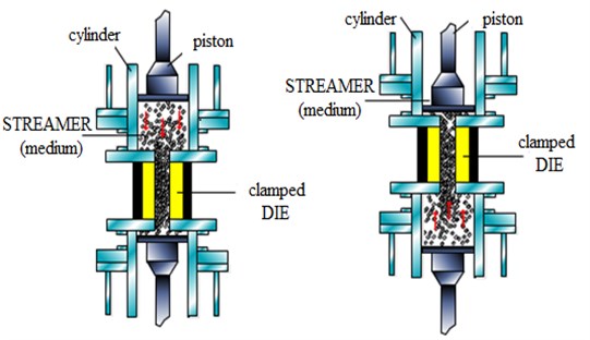
AFM is a polishing method, which is accomplished through viscoelastic soft abrasive media flowing back and forth on the machined parts surface under the pressure. The medium are used as many cutting tools to make repeated cutting with its hard and sharp edges on the surface, in order to achieve a certain degree of processing purposes [16]. The machining mechanism is illustrated in Fig. 1.
Fig. 1Principle of abrasive flow machining
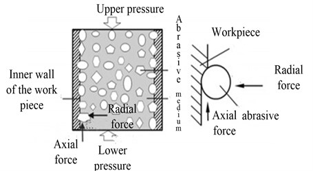
Abrasive wear is the main form of material removal during abrasive flow machining. The process is that the relative motion between hard particles and workpiece wall will produce wear to the wall of the workpiece. The steps of abrasive machining surface are as follows:
1) The abrasive grains are inserted into the workpiece surface by normal acting force, and the move in certain conditions.
2) Because of the horizontal cutting force, the abrasive grain and the surface of the workpiece produce relative sliding. So as to produce wear debris, wear scar, plastic deformation. Then the material on both sides of the indentation is destroyed, resulting in the surface of workpiece is squeezed out or off.
The force schematic diagram of the particles in the channel is shown in Fig. 2.
Fig. 2Schematic diagram of the force of particles in the channel
2. Materials and methods
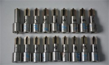
The experiment carried out different abrasive particle size, different abrasive concentration, different abrasive viscosity and different process time as key process parameters, which studied on process of abrasive flow machining in nozzle channel. The nozzle hole diameter was Φ0.16 mm and primary roughness of the inner channel was 1.64 μm. Nozzle parts were shown in Fig. 3.
Fig. 3The Part drawing of fuel spray nozzle after wire cutting
The experiment used self-developed abrasive medium which mixed certain volume fraction of silicon carbide abrasive particles with semi solid shape of the abrasive carrier. HL type hydraulic oil was the abrasive carrier, and the silicon carbide particles were solid particles, and other related auxiliary reagents were added. Because the nozzle orifice size was small, in order to make the abrasive medium with the ability to finish grinding and would not cause damage to the nozzle hole, small size silicon carbide particles should be chosen in the process of abrasive flow machining. On the basis of theoretical analysis and experimental study, abrasive particle size was 6 μm, 8 μm, 10 μm and 12 μm, and abrasive concentration was 4 %, 6 %, 8 % and 10 %. Test parameter settings were shown in Table 1.
Table 1Abrasive flow machining parameters
Designation | Parameter | Level | |||
1 | 2 | 3 | 4 | ||
A | Concentration of abrasive (%) | 4 | 6 | 8 | 10 |
B | Particle size of abrasive (μm) | 6 | 8 | 10 | 12 |
C | Viscosity grade (–) | VG22 | VG32 | VG46 | VG68 |
D | Processing time (s) | 60 | 90 | 120 | 150 |
The purpose of the single factor test design was usually to compare whether the different levels of the factors had differences and which one was better. When we needed to analyze the impact of multiple factors on the response value, the single factor rotation method was usually used to achieve. Single factor rotation experiment was to transform a multi factor test into a number of single factor test which can intuitively investigate basic changes in the effect of each factor.
3. Results and discussion
Analysis shows that the more evenly the scraping is, the better surface quality obtains.
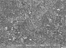
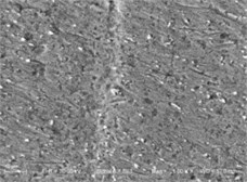
Fig. 4 (a) is the SEM of intersection of orifice before processing, and Fig. 4(b) is the one after processing. Fig. 4 shows that, after abrasive flow machining, channel surface becomes smoothing and it also has good effects on the nozzle and chamber pressure cross position to chamfering and deburring.
Fig. 4The SEM of fuel spray nozzle cross hole pre and post abrasive flow machining
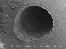
a) Pre abrasive flow machining
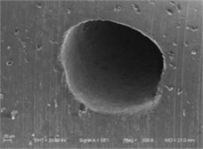
b) Post abrasive flow machining
3.1. Effect of abrasive concentration on the quality of abrasive flow machining
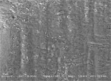
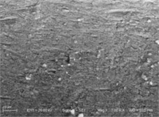
On the conditions that the abrasive viscosity grade is VG68, processing time is 150s and the abrasive particle size is 6μm, different concentration of abrasive is chosen on the nozzle channel for machining. The SEM of surface structure is obtained under the abrasive concentration of 4 %, 6 %, 8 % and 10 %, which are shown in Fig. 5.
Fig. 5The SEM of fuel spray nozzle hole after abrasive flow machining in different density
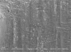
a) The concentration is 4 %
b) The concentration is 6 %
c) The concentration of 8 %
d) The concentration of 10 %
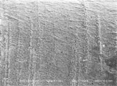
From the figures, the scratches of inner surface of nozzle channel obviously increase with increase of concentration of the abrasive. When the abrasive concentration is 4 %, there are only a few scratches on the inner surface of the nozzle channel. When it increases to 10 %, the number of scratches obviously increases and distribution tends to uniform. So, when the abrasive concentration is 10 %, the grinding effect is the best.
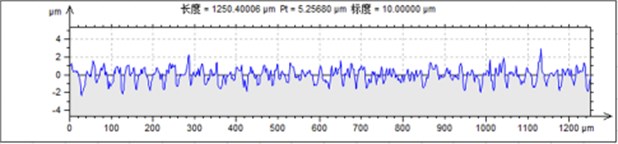
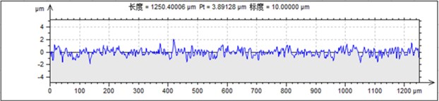
It is obtained from Fig. 6 that increasing the concentration of abrasive can improve the processing quality of abrasive grains. The fluctuation of the surface profile of the nozzle can be decreased with the increase of the concentration of abrasive. The higher the abrasive concentration is, the smaller the fluctuation of the surface profile will be. The surface of the nozzle channel is detected by raster scanner, and the test data are shown in Table 2 and Table 3. It can be seen that the numerical value and of surface roughness becomes smaller with increase of abrasive concentration.
Fig. 6Roughness detection under different abrasive density
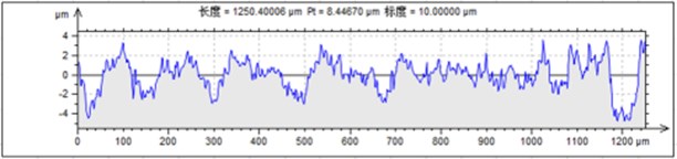
a) The abrasive density is 4 %
b) The abrasive density is 6 %
c) The abrasive density is 8 %
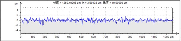
d) The abrasive density is 10 %
Table 2The surface roughness Ra test data
Concentration of abrasive (%) | |||||
Original value | 4% | 6% | 8% | 10% | |
Roughness value | 0.76937 | 0.76461 | 0.55341 | 0.38402 | 0.36149 |
Table 3The surface roughness Rz test data
Concentration of abrasive (%) | |||||
Original value | 4 % | 6 % | 8 % | 10 % | |
Roughness value | 6.03275 | 4.30630 | 3.36000 | 2.82459 | 2.63613 |
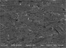
3.2. The effect of abrasive particle size on the quality of abrasive flow machining
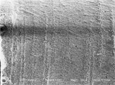
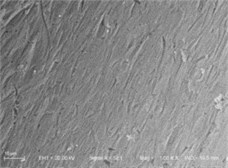
On the conditions that the concentration of abrasive is 10 %, the abrasive viscosity grade is VG68 and processing time is 150 s, different abrasive particle size is chosen on the nozzle channel for machining, and SEM diagrams of the channel surface quality of nozzle channel is obtained, which process from different abrasive particle size, which are shown in Fig. 7.
It can be seen from the graph that the flatness of the nozzle surface can be improved by using smaller particle size. It proves that on conditions of the same concentration of abrasive and abrasive viscosity and processing time, the smaller the particle size is, the better surface quality will be obtained. The results show that the best abrasive particle size is 6 μm.
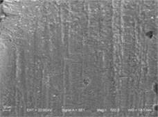
3.3. The effect of the abrasive viscosity on the quality of abrasive flow machining
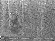
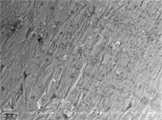
Liquid phase vector with different viscosity grades has different performance of carrying capacity of solid particles. Therefore, the viscosity of the abrasive will also directly affect the movement of solid particles in the nozzle channel. On the conditions that the concentration of abrasive is 10 % and the abrasive particle size is 6 μm and processing time is 150 s, different abrasive viscosity is chosen on the nozzle channel for machining. Fig. 8 shows the SEM picture of the surface structure of the nozzle channel surface with different viscosity grade.
Fig. 7The SEM of fuel spray nozzle channel after abrasive flow machining in different abrasive size
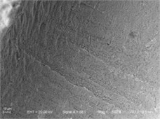
a) The abrasive size is 6 μm
b) The abrasive size is 8 μm
c) The abrasive size is 10 μm
d) The abrasive size is 12 μm
Fig. 8The SEM of fuel spray nozzle channel after abrasive flow machining in different viscosity
a) The viscosity grade is VG22
b) The viscosity grade is VG32
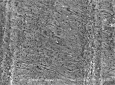
c) The viscosity grade is VG46
d) The viscosity grade is VG68
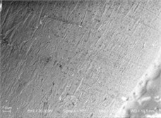
It can be seen from the figures that solid particles cause scratch on machined surface. The surface of nozzle channel has less scratches which are uneven distribution and not obvious in Fig. 8(a). And with the increase of the abrasive viscosity, the number of scratches on the wall have increased and become uniform distribution in Fig. 8(b), Fig. 8(c) and Fig. 8(d), especially The surface becomes smooth and fine in Fig. 8(d). It proved that in the process of machining nozzle, the cutting of the particle on the wall is weak and the randomness is large when the viscosity is small, and the machining of the nozzle wall is not obvious. With the increase of the abrasive viscosity, the number of scratches on the surface of the wall has increased, and the effect of cutting is enhanced. It is obvious that with the increase of the viscosity, the effect of abrasive flow on the injection nozzle passage becomes more obvious.
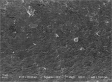
3.4. The effect of processing time on the quality of abrasive flow machining
Fig. 9 shows the SEM diagrams of the nozzle channel after abrasive flow machining which are on the conditions that the abrasive viscosity is VG68, the concentration of abrasive is 10 % and the particle size is 6 μm and the processing times are respectively 60 s, 90 s, 120 s and 150 s.
It can be seen from the Fig. 9, the scratches on the inner surface of the nozzle channel increase with the increase of processing time. When the processing time is 60 s, the inner surface of the nozzle channel has only a few scratches. And the number of scratches on the surface in the nozzle passage formed by abrasive flow machining increased obviously and the distribution is more uniform.
Fig. 9The SEM of fuel spray nozzle channel after abrasive flow machining in different machining time
a) The processing time is 60 s
b) The processing time is 90 s
c) The processing time is 120 s
d) The processing time is 150 s
4. Conclusions
It is found that when high concentration, fine particle size, high viscosity of abrasive is selected to process the non-linear pipe channel by abrasive flow machining, better surface quality is obtained. This is because that the viscidity of abrasive with high concentration and small particle size is better, and the greater the viscosity of the liquid phase carrier is, the greater the carrying effect of the solid particles will be. At the same time, the flow of high viscosity liquid drives the movement of particles, so that the mobility of the particles increases, and the machining of the workpiece is enhanced. After a certain time of abrasive flow machining of the non-linear pipe by using this kind of abrasive, better surface quality of the channel can be obtained. The surface roughness of the non-linear pipe passage is gradually decreased with the increase of the processing time. The best parameter combination which is obtained in this experimental condition is abrasive concentration of 10 %, the particle size of 6 μm, abrasive viscosity grade for VG68, the processing time for 150 seconds. Better surface quality can be obtained in the condition of the optimum parameters combination. The surface roughness Ra can be reduced to 0.6 μm from the original 1.64 μm.
The experimental results show that the self-developed abrasive grinding fluid applicable to non-linear tube hole channel of precision machining, which can effectively improve power post EDM surface channels uneven situation, and it also plays a role in the nozzle and chamber pressure cross position to the chamfering and deburring. It effectively improves the surface roughness and surface morphology of the nozzle channel, and reduces the resistance of the surface of the channel and the cross hole to the diesel oil and improve the quality of fuel injection nozzle parts. And it also has important significance to improve the atomization effect of fuel. It will provide support for seeking the best polishing process parameters and development of surface quality control of two phases abrasive flow.
References
-
Li Jun Ye, Ying, Yang, Li Feng Research on abrasive flow machining experiments of non-linear tubes. China Mechanical Engineering, Vol. 25, Issue 13, 2014, p. 1729-1734.
-
Sankar Mamilla Ravi, Ramkumar J., Jain V. K. Experimental investigation and mechanism of material removal in nano finishing of MMCs using abrasive flow finishing (AFF) process. Wear, Vol. 266, Issue 7, 2009, p. 688-698.
-
[Sankar Mamilla Ravi, Jain V. K., Ramkumar J. Experimental investigations into rotating workpiece abrasive flow finishing. Wear, Vol. 267, Issue 1, 2009, p. 43-51.
-
Kar K., Ravikumar N. L., Tailor P., Ramkumar J., Sathiyamoorthy D. Performance evaluation and rheological characterization of newly developed butyl rubber based media for abrasive flow machining process. Journal of Materials Processing Technology, Vol. 209, 2009, p. 2212-2221.
-
Kuan Yuchen, Ken Chuancheng A study of helical passageways applied to polygon holes in abrasive flow machining. The International Journal of Advanced Manufacturing Technology, Vol. 74, 2014, p. 781-790.
-
Wang A. Cheng, Cheng Ken Chuan, Chen Kuan Yu, Lin Yan-Cherng Enhancing the surface precision for the helical passageways in abrasive flow machining. Materials and Manufacturing Processes, Vol. 29, Issue 2, 2014, p. 153-159.
-
Zarepour H., Yeo S. H. Single abrasive particle impingements as a benchmark to determine material removal modes in micro ultrasonic machining. Wear, Vol. 288, 2012, p. 1-8.
-
Sushil Mittal, Vinod Kumar, Harmesh Kumar Experimental investigation and optimization of process parameters of Al/SiC MMCs finished by abrasive flow machining. Materials and Manufacturing Processes, Vol. 30, Issue 7, 2015, p. 902-911.
-
Venkatesh Gudipadu, Sharma Apurbba Kumar, Singh Nitish Simulation of media behaviour in vibration assisted abrasive flow machining. Simulation Modelling Practice and Theory, Vol. 51, 2015, p. 1-13.
-
Tan Yuan Qiang, Li Yi, Shen Yong On the model and pressure simulation of solid-fluid two phase flow for abrasive flow machining. China Mechanical Engineering, Vol. 19, Issue 4, 2008, p. 439-441.
-
Ji Shi Ming, Fu You Zhi, Tan Da Peng Numerical analysis and processing experiment of double-inlet restraint flow field in the soft abrasive flow machining. Journal of Mechanical Engineering, Vol. 19, 2012, p. 177-185.
-
Zhang Ke Hua, Min Li, Ding Jin Fu Micro-cutting of driving force and controllable influencing factors in abrasive flow machining. China Mechanical Engineering, Vol. 25, Issue 18, 2014, p. 2432-2438.
-
Zhang K. H., Shi Xu D. Y. C., et al. Investigation of material removal variations during abrasive flow machining. Materials Research Innovations, Vol. 18, Issue 2, 2014, S2-928-S2-931.
-
Ravikumar N. L., Kar K. K., Sathiyamoorthy D., et al. Surface finishing of carbon-carbon composites using abrasive flow machining. Fullerenes, Nanotubes and Carbon Nanostructures, Vol. 20, Issue 2, 2012, p. 170-182.
-
Singh S., Shan H. S., Kumar P. Experimental studies on mechanism of material removal in abrasive flow machining process. Materials and Manufacturing Processes, Vol. 23, Issue 7, 2008, p. 714-718.
-
Wan S., Ang Y. J., Sato T., Lim G. C. Process modeling and CFD simulation of two-way abrasive flow machining. The International Journal of Advanced Manufacturing Technology, Vol. 71, 2014, p. 1077-1086.
Cited by
About this article

The authors would like to thank the National Natural Science Foundation of China No. NSFC 51206011, Jilin Province Science and Technology Development Program of Jilin Province No. 20160101270JC and No. 20170204064GX, Project of Education Department of Jilin Province No. 2016386.
