Abstract
In this paper, the method of spatial information extraction of tree branch was studied. The region matching method was used to get the disparity map of stereo image, extracted feature points combining with branch skeleton image by multi-segment approximation method, and calculated the spatial coordinates and the radius of branch feature points by using binocular stereo vision. Real-time model reconstruction for fruit tree has been researched on. Test proposed that each branch module was constructed by 12-prism in the coordinate origin, and then rotated twice and translated once to get correct posture, finally combined with other modules for the fruit tree model. Test has optimized extraction algorithm and matching algorithm of the branch region, improved matching rate, reduced matching errors, avoided matching confusion, accurately extracted branch spatial information and improved the success rate of robot path planning for obstacle avoidance.
1. Introduction
The intelligent harvesting robot is an effective solution approach for the reduction of agricultural labor force and the high cost of fruit picking. Unstructured working environment is the biggest problem for harvesting robot. As the spatial location and posture of fruit are random, the existence of branches and other obstacles are the hidden dangers of the harvesting robot. Therefore, the identification and location of obstacles is a new problem. After the acquisition of branch spatial information, their 3D models are reconstructed by using appropriate method. In the work scene model, path planning for fruit picking are carried out to make robot real-time, securely, nondestructively pick fruit.
In the whole harvesting process, there are two key issues: identification and picking. So, the system must have two functions, by which obtain the identification information from the fruit data and obstacle avoidance information from the branch data. Until present, binocular stereo vision system is the best choice for the whole process system and connection platform have known. In the picking part, it is easy to reconstruct the real-time model and supply the data for obstacle avoidance by binocular stereo vision system. And in fact, when the model was reconstructed, the data transformation from that could supply enough data for the obstacle avoidance [1].
In 3D modeling, decompose a complicated object into simple modules, and then combine them according to a given rule. For three-dimensional modeling, this method of complexity-simpleness-complexity [2-9] is important. It is well known that OpenGL include the standard modules, if a module could be found that satisfies the rapid fruit model construction, all problems would become simple following the thinking mentioned before. In this paper, the cylinder module is choosing because though the tree's shape is complicated, the branch is made from a great deal of cylinders.
2. Extraction of branches information
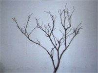
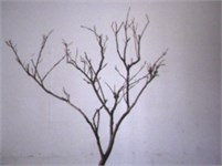
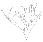
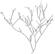
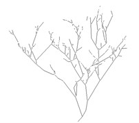
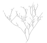
Extraction of branches features information of fruit trees is to reconstruct tree model based on these features. From the scene images Fig. 1, it can be seen that the shape of branches are complex, it is very difficult to recover the branches 3D information. There are straight branches and curved branches. Reconstruction cylindrical through branch endpoints and radius can characterize direct branches, but not to characterize curved branches.
In this study, first, extract the tree skeleton, and then fit tree branches skeletons by multi-segment approximation method to obtain feature points coordinate information and extract radius information of the characteristic points by the branch range image. Finally, the original branches are reconstructed by multi cylindrical.
Fig. 1Scene image and binary image of branch
a)
b)
2.1. Skeletons extraction
Skeleton is the core part of the object, and the objects of different shapes have different skeletons. In general, the skeleton has three main characteristics: continuity, the minimum width is 1, and centrality [10]. Currently, extraction method of region skeleton mainly includes morphology method, distance transform and thinning method, etc.
1. Morphology method. Morphological method is a way to corrode awaiting processing region with a structure element, and then add each last time result before corrosion to empty set to get region skeleton [11]. But, this method can’t guarantee the connectivity, when the edge is not smooth or the width sudden changes in the region, that will cause skeleton points detected from the continuous region discontinuous.
2. Distance transform. Distance transform method extract region skeleton in two steps by distance transform and skeletonization. In this method, the range image is obtained through distance transform, the size of each pixel value in the range image directly reflects the distance from the pixel to edge; Then comparing the distance value of pixel in the range image, all the set of pixels which’s distance value are greater or equal to the maximum distance value of the neighborhood is used as region skeleton.
Distance transform method extract region skeleton points by range image. For the largest distance points in each row (or column) are only related to the edge, the skeleton points location relationship of adjacent two rows (or two column) is not necessarily related, when the edge is not smooth or the width sudden changes in the region, that will cause discontinuous skeleton points detected from the continuous region or generate noise points, which will cause difficulty in further processing.
3. Thinning method. Region thinning method thins the region to get line graph constituted by lines with small memory capacity and ease to be identified. In order to make line graph accurately represent the shape of the object, the thinning must meet the following requirements:
(1) The line-width is one pixel;
(2) Thin position lies in the center of the original region;
(3) Graph’s connectivity keeps invariant, and the hole and points can’t new increase or disappear;
(4) The graphic ends keep invariant.
So, one can see, the essence of region thinning is the process of finding the center line of graph without changing the length and the connectivity of graph.
There are various thinning methods, this paper adopts Yokoi thinning method to implement thinning region. When Yokoi thinning method repeatedly removing pixels in the surface of graphics, the graphic surface pixels are divided into upper-lower surface pixels and left-right surface pixels, and forward scanning and reverse scanning are alternately carried out to remove upper-lower surface pixels and left-right surface pixels until the center line was obtained.
In this study, the region skeletons extracted by Yokoi thinning method keep the connectivity of original region with better effect Fig. 2.
Fig. 2Features extraction of branch
a) Branch range image
b) Branch skeleton
c) Multi-segment approximation image
d) Overlay
2.2. Skeleton pruning
Although the branches skeletons processed by thinning keep a good connectivity, it will lead to “false branch” Fig. 2(b) when the edge is not smooth. The Spurs don’t affect the overall structure of the branches, but will increase computational complexity, which should be removed. At present, the common skeleton pruning method is morphology method [12]. But morphology method can only prune short branches (not more than three pixels, the glitch), because the falsest branches in this study are more than 3 pixels, morphology method can’t prune that. In this study, the length of branch skeletons counted, and then set the threshold for the length to remove the false branch, the concrete process are as follows:
1) Scanning skeleton image to find the branch points () and endpoints () of the skeleton, and copy the skeleton image;
2) In the copy image, the pixels in the eight neighborhoods of the branch point are changed into background points, as the branch point is the connection point of several branches, when eight neighborhood points of the branch points are changed into background points, these branches will be divided into some separate branch segments;
3) Label each branch and count the length of that;
4) Judge each branch skeleton in skeleton image, if two endpoint of the skeleton are both branch points, then this skeleton is in the tree trunk which can’t be removed; if the two endpoints are both the endpoints, then the skeleton is an independent skeleton and not the branch section which can’t be removed; if only one point between two endpoints of the skeleton is the branch point, the skeleton isn’t the trunk, and then judge its length, if the total number of pixels less than 15, indicating that the skeleton is the “false branch” which should be removed.
With the above processing, the skeleton glitch and “false branch” are effectively removed, the number of feature points and branches are significantly reduced, so as to simplifying the subsequent processing.
3. Acquiring 3D information
This paper extracts the branch 3D information by binocular stereo vision technology, which includes the space coordinate of branch feature points and the radius of the branch. Because there are many feature points for one breach, feature points matching is unsuitable for branch matching.
Region matching is to select a region (window) with one point as the center in an image, find the region with the greatest correlation degree to the window region in another image, and the center of the maximum correlation region found is used as the corresponding point of original regional centre, the disparity of the whole image can be obtained. So, region matching is suitable for branch matching in this study.
Typically, the gray matching method is the fastest way to reconstruction. Sum of absolute gray value differences (SAD) and sum of squared gray value differences (SSD) are two methods of similarity measure [16, 17]. The definition as follows:
SAD and SSD are sensitive to illumination variation. As the shading of tree, and the different viewpoint of two cameras, illumination variation often occurs. Therefore, this study used normalized cross-correlation (NCC) method:
and (, ) respectively represented mean value and standard deviation of the window in the left and right image. NCC has the advantage of anti interference to illumination variation, but with slightly longer computation time.
To find the match point in the left image, similarity measure should be calculated along the entire epipolar line in the right image. However, the disparity of the point related to the depth, which is decreased with depth increased, the disparity of infinite point can be seen as 0. Depth range of the object can set disparity search. A smaller searching range of disparity can be set by depth range of the object.
Therefore, , (min disparity) and (max disparity) can be calculated by the depth extreme value. After the calculation of similarity measure for a point, the matching point is based determined by the maximum value of the NCC. However, the occlusion may result in failure matching of the pixels, a threshold value of similarity is set, and only when the pixel similarity measure is above this threshold, the matching results are accepted. Obviously, the setting for the threshold may result in multiple matching [18].
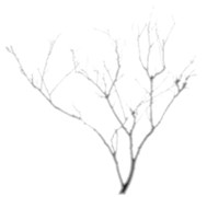
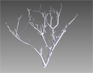
Fig. 4Disparity image using area-based matching and skeleton image
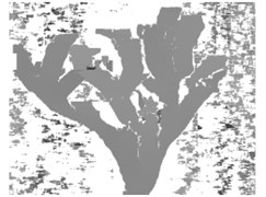
a) Disparity image
b) Skeleton image
c) Skeleton image processed by “and operation”
In this study, the distance from fruit trees to the camera is between 1.0-2.0 m, by calculating the disparity search range of 96 and 48 can be set. After two original images are converted to grayscale images, the two images are matched with setting 15×15 matching window by NCC method. Texture validation and uniqueness validation are set to prevent the match pixels generated by window texture level being declared to be invalid pixels and to optimal select one of the best match points from multiple matching pixels. Disparity image are shown in Fig. 4(a), Fig. 4(c) is the result of “and operation” between Fig. 4(a) and Fig. 4(b), which represents branches that can be measured. By comparing Fig. 4(c) and 4(b), it can be found in Fig. 4(c) that some of region skeletons are reduced, this is because part of the branches can’t find the matching points.
4. 3D reconstruction based OpenGL
Harvesting robot is complex and expensive, which is eased to be damaged by branches and other obstacles when picking citrus, apples and other fruits of tall trees. It is necessary for harvesting manipulator to possess the function of obstacle avoidance, as will ensure the occlusion fruit are picked safely and successfully. The premise conditions for obstacle avoidance are the perception of obstacle information in the robot work space and the reconstruction of scene model. The work scene includes fruits, leaves and branches, the fruits are the work target and the leaves will not cause damage to the robot, so that reconstructing branch model is enough.
On the basis of fitting branch by multi-segment approximation and branch feature extraction, the unit module is constructed by the 12- prism method, and then assembled into the tree model.
Fruit trees are with complexity structure and large individual differences, the breaches are composed of large number of truncated cones with constantly changing radius. The unit module is constructed branches have been divided into many segments by multi-segment approximation and extracted the 3D coordinate and radius of feature point. The data of each branch is stored as which is the necessary data for constructing unit module. Model is constructed by using OpenGL in VC platform.
4.1. Unit model construction
The basic elements of the model are the model vertices. The vertices branch is located on the bottom of both endpoints of the branch, in order to describe each branch model, it needs to calculate the space coordinates of 24 points on the two bottoms. Since the position and pose of each branch is random, computing for the 24 points is very complicated. To reduce computational complexity of unit module, this study made coordinates of circle center on the bottom coincide with coordinate origin. The branch model’s height can be calculated by Eq. (5):
The coordinates and radius of circle centers on the bottom of the two cylinders are changed into . Through the radius information of and , the coordinates of 12 equal diversion points (vertices) of the circle with radius on the plane of were calculated out and the coordinates of 12 equal diversion points (vertices) of the circle with radius on the plane of were calculated out.
The 24 vertices were connected by the connection order of standard model so as to get a branch module.
4.2. Scene model combination
Each branch unit model needed to be moved to correct position with the original pos and composed of scene model with other model.
By spatial position transformation law, unit model will recurrence the branch original position and pos by twice rotations and once translation. Taking the cylindrical module for example, the transform process of module position and orientation is briefly introduced.
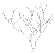
Each branch model in the scene was transformed by above methods to obtain scene tree model, shown in Fig. 5.
Fig. 5Scene model of virtual reconstruction
a) Front view
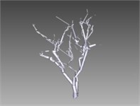
b) Left view
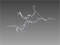
c) Top View
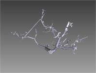
d) Bottom view
5. Conclusions
This paper has studied the method of spatial information extraction. Experiment used the region matching method to obtain the disparity of each pixel matched, extracted feature points combining with branch skeleton image by multi-segment approximation method, and calculated the spatial coordinates and the radius of branch feature points by using binocular stereo vision. Real-time model reconstructing for fruit tree has been researched on. Test has optimized extraction algorithm and matching algorithm of the branch region, improved matching rate, reduced matching errors, avoided matching confusion, accurately extracted branch spatial information and improve the success rate of robot path planning for obstacle avoidance.
Real-time model reconstruction for fruit trees had been researched on. Test proposed that each branch module was constructed by 12-prism in the coordinate origin and then in the space of tree build paragraphs, and then rotated twice and translated once to get correct posture, finally combined with other modules for the fruit tree model. Documents required for obstacle avoidance and path planning is analyzed, and the relationship between model accuracy and model generation time was found by comparing the model generation time in different condition. Experiments show that the fruit tree model provide environmental reference for obstacle avoidance and path planning of the fruit harvesting robot, and the speed and the accuracy essentially meet the requirements.
References
-
Szostak M., Wężyk P., Pająk M., et al. Determination of the spatial structure of vegetation on the repository of the mine “Fryderyk” in Tarnowskie Góry, based on airborne laser scanning from the ISOK project and digital orthophotomaps. Geodesy and Cartography, Vol. 64, Issue 1, 2015, p. 87-99.
-
Yan H., Kang M. Z., Reffye P. D., et al. A Dynamic, architectural plant model simulating resource-dependent growth. Annals of Botany, Vol. 93, Issue 5, 2004, p. 591-602.
-
Jansson S., Douglas C. J. Populus: a model system for plant biology. Annual Review of Plant Biology, Vol. 58, Issue 1, 2007, p. 435-458.
-
Shlyakhter I., Rozenoer M., Dorsey J., et al. Reconstructing 3D tree models from instrumented photographs. IEEE Computer Graphics and Applications, Vol. 21, Issue 3, 1999, p. 53-61.
-
Wang R., Hua W., Dong Z., et al. Synthesizing trees by plantons. The Visual Computer, Vol. 22, Issue 4, 2006, p. 238-248.
-
Liang H. Design and realization of the 3D digital campus based on sketchup and ArcGIS. Geospatial Information, 2014, p. 132-137.
-
Biljecki F., Ledoux H., Stoter J., et al. The variants of an LOD of a 3D building model and their influence on spatial analyses. ISPRS Journal of Photogrammetry and Remote Sensing, Vol. 116, 2016, p. 42-54.
-
Jabr F. Building tastier fruits and veggies (No GMOs required). Scientific American, Vol. 311, 2014, p. 56-61.
-
Xiang L. I. Optimized disquisition on basic arithmetic in 3D scene emulator. Computer Engineering and Applications, Vol. 44, Issue 7, 2006, p. 123-125.
-
Zhang T., Mu D., Ren S. An algorithm based on skeleton extraction and inscribed sphere analysis for 3D model information hiding. International Journal of Advancements in Computing Technology, Vol. 4, Issue 1, 2012, p. 453-462.
-
Yang C. L., Meng X. X., Li X. Q., et al. Undigraph based whole expression model and algorithm for the skeleton of an image. Chinese Journal of Computers, Vol. 2000, Issue 3, 2000, p. 293-299.
-
Corke P. I. Machine vision. Moldes, Vol. 19, Issue 3, 2000.
-
Zimmer Y., Tepper R., Akselrod S. An improved method to compute the convex hull of a shape in a binary image. Pattern Recognition, Vol. 30, Issue 3, 1997, p. 397-402.
-
Yaroslavsky L. P. Fast transforms in image processing: compression, restoration, and resampling. Advances in Electrical Engineering, Vol. 2014, Issue 90, 2014, p. 1-23.
About this article

This work was supported by the foundation of Zhejiang Educational Committee (Grant No. Y201432724, Y201533234, 2017C35001, 2016C11018), the foundation of Ningbo Science Bureau (Grant No. 2015C10050, 2016C10056, 2016A10003, 2016C11018).
