Abstract
The paper refers to development of relationship between fatigue life and energy dissipated during process of fatigue. A theory about treating technical object as operational system, with limited potential for destruction was utilized. On the base of experiments, it was stated, that dissipated energy, which is stored in the object as a result of various kinds of wear processes, including fatigue can be such parameter. Amount of this energy was determined experimentally. It was found, that “consumption” of this energy depends on the value of the damping coefficient of the test object and the parameters of the oscillatory motion. Knowing the amount of this energy and accepting it as a "destruction capacity”, it is possible to predict the fatigue life of an object under a given load.
1. Introduction
The quality of machines operating can be described -among others - by parameters of their technical condition. These parameters are determined by the severity of wear processes taking place in the objects during their lifetime. Ability to identify, or even more important, forecasting this state is crucial from the point of view of rational operational decisions. Whole series of papers refer to this issue. For instance [1] summaries and review developments in diagnostics and prognostics of mechanical system with emphasis on models, algorithms and technologies for data processing and maintenance decision-making. The use of vibro-acoustic nonlinear wave modulations for prediction of cracked aluminum plate is described in [2]. Methods for predicting rotating machinery failures are summarized and classified as conventional reliability models, condition-based prognostics models and models integrating reliability and prognostics are given in [3]. Common causes of damages are related to wear processes. Creating possibilities for precise – based on the current stage of such processes, not on likelihood - prediction the appearance of the failure (damage) is therefore extremely important, especially for those industries which use complex and responsible machinery and equipment.
The essence of the problem of damage prediction is the difficulty in the quantitative description of the severity of wear processes taking place in the technical objects. One of the most common causes of failures is fatigue wear. The problem lies in the fact that phenomena of fatigue, having a large effect on the durability and reliability of technical objects are not yet sufficiently clarified. Computational methods are rather related to design stage and generally are based on empirical generalization. The result is that the technical concept of “fatigue” is generally seen as certain probability of damage after a certain number of cycles of load, which should not be exceeded. Some methods are given in literature. For instance, in [4] a time-based method is proposed to analyze the fatigue crack growth behavior under variable amplitude loading caused by vibration. Spectral method for assessing the fatigue lives of mechanical components under non-Gaussian random vibration loadings id described in [5].
Treating technical objects as behavioral systems, it can be said that they are systems that transform energy into useful energy (in the form of e.g. desired product or the work process) and energy dissipated externally and internally [6]. This last one is stored internally in the object as a result of various kinds of wear processes occurring during operation.
Energy dissipation can be modelled using frictional, hysteretic or thermo-elastic mechanisms [7]. As example, in [8] vibrothermography method that detects surface temperature changes due to heating associated with frictional energy dissipation by damage is presented. Concept of energy dissipation was also used for identification of structural supporting layer of the foil bearing model [9]. Fundamentals of the concept of energy dissipation in the diagnosis are included in the works [10-13]. Concept of Energy dissipation was also used in [14] for measuring of vibration damping of shot‐filled containers with some empty volume as the shot damper clearance.
Deformation (fatigue) of machine elements under the influence of external forces is always accompanied by internal friction. Heat emission is the symptom of this phenomena. In case of exceeding the limit of elasticity, permanent deformation appears caused by plasticizing material and decohesion.
Such energy is lost energy as opposed to elastic energy which is returned after unloading. It can be assumed that dissipative energy is the destructive energy [15] and the identification process of its transformation can be used to predict the durability of machine parts. Treating technical objects as behavioral systems, it can be said that they are systems that transform energy into useful energy (in the form of e.g. desired product or the work process) and energy dissipated externally and internally. This last one is stored internally in the object as a result of various kinds of wear processes occurring during operation.
Theories of ideal medium can be used to describe the energy transformation: the energy changes in cyclically deformed element machine can be described on the basis of appropriate connecting models: spring (Hook), viscous (Newton) and plastic (Saint-Venant). Dissipated energy can be determined using Newton and Saint-Venant models [17-19].
Accurate prediction of fatigue life of machines, equipment and structures is critical for some industries like petrochemical for instance where extremely important in operating conditions may be possibility of detecting the dangers associated with the fatigue early enough, that machine or the entire production process can be safely switch off, even if degradation is already irreversible.
2. Test stand description
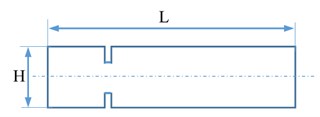
Neodymium fatigue machine NMZ-1 (Fig. 1) designed and built within the framework of the research project [10]. The machine is a non-contact bending device, consists of three independent measuring sections. The sample (Fig. 2) is placed in the jaw holder between two disks with neodymium magnets fixed on the motor shaft. Rotation of discs through neodymium act on a test sample causing it to swing from the state of equilibrium. Value of forces acting on the sample is combination of the distance between the discs, installed power neodymium magnets and the length of the sample. The frequency depends on the rotational frequency of the motor. The following parameters are recorded: number of fatigue cycles, displacement (amplitude) of test sample and its temperature. There is also the opportunity to evaluate a number of other process parameters of test sample deformation such as stress in the cross-notched specimen, and the loading force (focused) at the end of the sample.
Fig. 1Neodymium machine NMZ-1
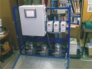
a) General view of the device
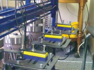
b) View the section handles with measurement sensors
Fig. 2The basic dimensions of the sample. L= 180 mm – length of the sample, H= 25 mm – the width of the sample; g= 2 mm – thickness
3. The test procedure and results
A series of experiments involving subjecting the samples made of steel S 235 to fatigue loads of a certain frequency and amplitude were carried out. The selection of frequencies and amplitudes extortion was made by analyzing the functioning of the common piping and sources of their vibration (mechanical force, acoustic, pulsations of medium) because ultimately the results of the research will serve the development of test methods for so-called SBC (Small Bore Connection).
The frequency excitations varied in the range of 1 to 50 Hz, and they were respectively equal to 10, 15, 17 (the resonance frequency of the sample), 25, 35 and 50 Hz. Following values were recorded – the RMS value of relative vibration (displacement), the number of cycles and the time to failure of the sample. For each frequency, the measurements were done for 5 samples. Spectral analysis of sample vibration was done.
Fig. 3 shows an example of a sample answer - simple, with one harmonic and complex – with visible other harmonics of sample response.
Table 1 summarizes obtained results (for each experiment, average value from 5 samples/measurements). The last two columns of the table show the values and the frequency of the next after the first, significant (largest) signal component (mostly the second or third harmonic).
Fig. 3Sample spectra of samples of the response signal
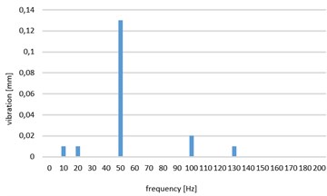
a) The answer simple, with one first harmonic
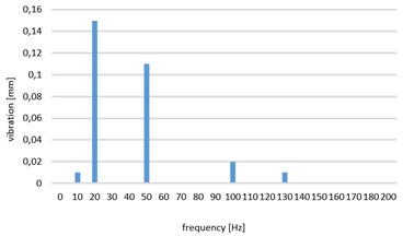
b) The answer complex with visible successive harmonics
Table 1Values of excitation vibrations frequency and amplitude response
No. of experiment | Number of cycles to destruction | Time to failure [s] | Excitation frequency [Hz] | RMS of sample vibration [mm] | Value of 1st harmonic [mm] | Value of next significant harmonic [mm] | The frequency of next significant harmonic [Hz] |
1 | ∞ | ∞ | 10 | 0.15 | 0.15 | 0 | 0 |
2 | 880 000 | 58 667 | 15 | 0.27 | 0.22 | 0.14 | 75 |
3 | 200 000 | 11 765 | 17 | 0.56 | 0.49 | 0.28 | 68 |
4 | 2 000 000 | 76 923 | 26 | 0.19 | 0.15 | 0.11 | 78 |
5 | 280 000 | 8 000 | 35 | 0.48 | 0.28 | 0.39 | 70 |
6 | 1 100 000 | 22 000 | 50 | 0.36 | 0.36 | 0 | 0 |
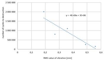
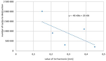
Fig. 4 shows the relationship between the RMS value of displacements of the sample (Fig. 4(b)) and the value of the first harmonic of the sample displacement (Fig. 4(a)) and the number of cycles for destruction. Trend lines (linear) with equations are noted on figures. From the graphs it is clear and obvious statistical relationship between the values of the vibration amplitude and the number of cycles but a relatively large standard deviations, in particular for the first harmonic do not allow for accurate prediction of time to failure (statistical analysis of the test results is not shown in this article).
Fig. 4Relationship between the a) the value of the first harmonic of the sample displacement and b) RMS value of displacements of the sample and the number of cycles for destruction
a)
b)
Analysis of these drawings leads to the conclusion that accurate prediction of the fatigue life should refer not only to value of vibration but also to nature of the response. Attempt was made to determine the relationships between the fatigue strength of samples and the parameters of the responses (amplitude and frequency) by calculating energy dissipated internally throughout the experiment.
It is assumed, that generated deformation are within the limits of elasticity. Then, in the bending process part of energy supplied is recovered after relaxation of the sample which can be described by the Hook model and part is converted to heat due to internal friction in the sample which can be described by the Newton model. For this reason, the description of the phenomenon analyzed model is adopted Kelvin-Voigt:
where: [N] – the force that causes deformation (not taking into account the forces of inertia), [N/m] – coefficient of elasticity, [Ns/m]– coefficient of damping, [m] – coordinate of the center of gravity of the sample during test, [m/s] – velocity of the sample center of gravity during test.
It was assumed that energy dissipated during test will be calculated as the sum of the individual components of the vibration response of the sample. After transformations which considered internal friction force and distance to overcome by the sample center of gravity during fatigue test, for complex harmonic motion Eq. (2) was obtained:
where – amplitude of -harmonic in sample response [m], – frequency of -harmonic in sample response [Hz], – number of harmonics in sample response, – time to destruction [s].
This model allows to determine energy dissipated internally during the whole process of sample destruction. This energy depends on the amplitude and frequency of vibration and the value of damping factor. It should be noted that the elastic material (value near zero), the value of this energy is also strives to 0.
The results of calculations of dissipated energy are shown in Table 2. Value of damping coefficient c for tested samples is equal to 0,085 N·s/m [10].
Fig. 5 shows the relationship between energy dissipation and number of cycles to destruction.
For the obtained results, the equation of trend (linear) is given by formula:
Experiment No. 3 was carried out in resonance frequency. If the result obtained in this experiment is not included, the graph will take the form as shown in Fig. 6.
Table 2Results of experiments
No. of experiment | Number of cycles to destruction | Time to failure [s] | Energy dissipation [J] |
1 | ∞ | ∞ | ∞ |
2 | 880 000 | 58 667 | 96 654 |
3 | 200 000 | 11 765 | 69 107 |
4 | 2 000 000 | 76 923 | 92 926 |
5 | 280 000 | 8 000 | 91 537 |
6 | 1 100 000 | 22 000 | 96 941 |
Fig. 5Relationship between energy dissipation and number of cycles to destruction
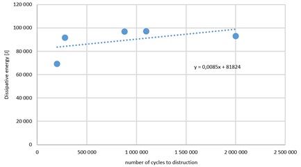
Fig. 6Relationship between energy dissipation and number of cycles to destruction without experiment done in resonance frequency
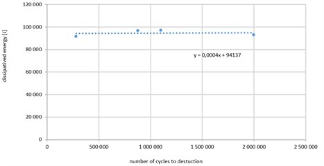
Equation of trend (linear) is than given by formula: .
Analyzing the results, it was found that: 1) for excitations, as a result of which the amplitude response of samples (RMS) was less than 0.2 mm (irrespective of the composition of the frequency response), the sample is not damaged. For such conditions, dissipated energy tend to infinity without sample destruction. 2) for greater excitations, it was found that the amount of energy dissipated is almost constant, irrespective of the number of cycles to failure with slope line trend equation equal to 0.0085. If experiment no 3 (carried out in resonance frequency) is not taken into account, value of slope is equal to 0,0004. Average value of dissipated energy is equal to app. 95 kJ while standard deviation is equal to 2,7 kJ what is 2,8 % of average value.
4. Conclusions
As a result of experiment, it was found that the fatigue life depends not only on the vibration amplitude but also on composition of the frequency response signal. The relationship between the dissipated energy in the process of fatigue, number of cycles to the destruction and vibration parameters of response signal was determined. It was found that value of this energy, regardless of the experimental conditions is almost constant – the standard deviation is about 2.8 % of the average. Therefore, conclusion confirming the theory about the technical object as operational system, with limited potential for destruction [5] can be drawn. In this case it is amount of dissipated energy, which is stored in the object as a result of various kinds of wear processes, including fatigue. Amount of this energy can be determined experimentally while “consumption” of this energy depends on the value of the damping coefficient of the test object and the parameters of the oscillatory motion. Knowing the amount of this energy and accepting it as a “destruction capacity”, it is possible to predict the fatigue life of an object under a given load.
References
-
Jardine A. K. S., Lin D., Banjevic D. A review on machinery diagnostics and prognostics implementing condition-based maintenance. Mechanical Systems and Signal Processing, Vol. 20, Issue 7, 2006, p. 1483-1510.
-
Klepka A., Staszewski W., Jenal R., Szwedo M., Iwaniec J., Uhl T. Nonlinear acoustics for fatigue crack detection-experimental investigations of vibro-acoustic wave modulations. Structural Health Monitoring, Vol. 11, Issue 2, 2012, p. 197-211.
-
Heng A., Zhang S., Tan A. C. C., Mathew J. Rotating machinery prognostics: State of the art, challenges and opportunities. Mechanical Systems and Signal Processing, Vol. 23, Issue 3, 2009, p. 724-739.
-
Jiang S., Zhang W., Wang Z. A vibration fatigue analysis model considering interaction effects. Journal of Vibroengineering, Vol. 17, Issue 7, 2015, p. 3650-3661.
-
Cheng H., Tao J., Chen X., Jiang Y. A spectral method to estimate fatigue life under broadband non-Gaussian random vibration loading. Journal of Vibroengineering, Vol. 16, Issue 2, 2014, p. 596-607.
-
Cempel C. Holistic model of degradation processes in mechanical systems. Diagnostyka, Vol. 29, 2003, p. 7-14, (in Polish).
-
Broda D., Staszewski W., Martowicz A., Uhl T., Silberschmidt V. V. Modelling of nonlinear crack–wave interactions for damage detection based on ultrasound – a review. Journal of Sound and Vibration, Vol. 333, Issue 4, 2014, p. 1097-1118.
-
Pieczonka L., Staszewski W., Ymerich F., Uhl T., Szwedo M. Numerical simulations for impact damage detection in composites using vibrothermography. IOP Conference Series: Materials Science and Engineering, Vol. 10, Issue 1, 2010, p. 12062.
-
Żywica G., Kiciński J., Bagiński P. The static and dynamic performance analysis of the foil bearing structure. International Conference on Vibration Problems ICOVP, Lisbon, 2013.
-
Winiwarter P., Cempel C. Life symptoms: the behavior of open systems with limited energy dissipation capacity and evolution. Systems Research, Vol. 9, Issue 4, 1992, p. 9-34.
-
Natke H., Cempel C. Model-Aided Diagnosis of Mechanical Systems: Fundamentals, Detection, Localization, Assessment. Springer Science and Business Media, 2012.
-
Cempel C. Fundamentals of Vibroacoustical Condition Monitoring. Handbook of Condition Monitoring, Springer Netherlands, 1998.
-
Cempel C., Natke H. Damage evolution and diagnosis in operating systems. Safety Evaluation Based on Identification Approaches Related to Time-Variant and Nonlinear Structures. Verlag, p. 44-61, 1993.
-
Cempel C., Lotz G. Efficiency of vibrational energy dissipation by moving shot. Journal of Structural Engineering, Vol. 119, Issue 9, 1993, p. 2642-2652.
-
Lin X., Haicheng G. Plastic energy dissipation model for lifetime prediction of zirconium and zircaloy-4 fatigued at RT and 400 °C. Journal of Engineering Materials and Technology, Vol. 120, Issue 2, 2001, https://doi.org/10.1115/1.2806998.
-
Szczyglak P. Stability analysis of a machine unit against the background of modeling its dynamics. Maintenance and Reliability, Vol. 4, 2006, p. 46-50.
-
Szczyglak P. Modeling the Flexibility of Pneumatic Tired Wheels Moving on the Soil Surface. Technical Sciences v.9, UWM, 2006.
-
Masoud Hassani M., Wittel F. K., Hering S., Herrmann H. J. Rheological model for wood. Computer Methods in Applied Mechanics and Engineering, Vol. 283, Issue 1, 2015, p. 1032-1060.
-
Napiórkowski J., Rychlik A., Szczyglak P., Kołakowski K., Ligier K., Mikołajczak P., Drożyner P. Research and Modeling of Abrasive Wear and Fatigue. University of Warmia and Mazury in Olsztyn, 2014.
