Abstract
Vibration-based damage detection is based on the fact that vibration characteristics such as natural frequencies and mode shapes of structures are changed when the damage is happened. The vibration-based damage detection of a beam is formulated as a single-objective optimization problem in which genetic algorithm (GA) is used as the optimizer. This paper presents the encoding by locations and damage factor (ELD) which employs location and damage amount as the decision variables. The proposed encoding can reduce the number of decision variables that used in the previous encoding, the encoding by damage factor of each element (EDE). The search space of GA with ELD is then smaller than that of GA with EDE. The simulation results reveal that GA with ELD can identify the damage occurred in the beam more correctly than GA with EDE. Moreover, the damage predicted by GA with ELD is quite close to the actual damage for all 3 test cases.
1. Introduction
The vibration-based damage detection methods are non-destructive methods, which are important for structural integrity testing. When there is some damage in the structure, vibration characteristics such as natural frequencies and mode shapes are changed. These vibration characteristics are actually related to structural physical parameters such as mass, stiffness, and damping of the structure. The structural damage causes a reduction of structural stiffness so that vibration characteristics are consequently changed. Many applications in engineers [1, 2] employed the vibration-based damage detection methods.
This method formulates structural damage identification to an optimization problem, the optimization algorithm is then to be used in this method. Genetic algorithm (GA) [3] is used as the optimization algorithm in this paper. GA is a derivative-free population-based optimization method of which search mechanisms are based on the Darwinian concept of survival of the fittest. A number of previous works such as [4, 5] employed GAs as the optimizers in vibration-based damage detection in beams. In addition, there are many researches such as [6, 7] employed other artificial intelligence techniques for the damage detection in beams.
In previous works [4, 8], the encoding by damage factor of each element (EDE) in which a decision variable represents damage amount of each of divided elements is used. The number of decision variables is directly equal to number of divided elements in the objective calculation. In order to reduce the number of decision variables, this paper will propose the encoding by locations and damage factor (ELD) in which location and damage amount are used as the decision variables.
2. Objective calculation
For free vibration of undamped structures, the equation of motion is given by the following equation:
where [] and [] are mass and stiffness matrices respectively. The corresponding eigenvalue equation for vibration mode is given by:
where and are eigenvalue, the square of nature frequency, and eigen vector or mode shape of th mode of vibration.
Fig. 1A divided element for finite element model
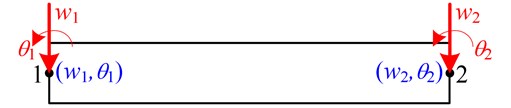
This paper uses the finite element method (FEM) for beam in which Fig. 1 shows a divided element. At each nodal point, there are 2 degrees of freedom which are deflection in vertical direction (), and angle of rotation (). There are 2 nodal points of the divided element so that 4 degrees of motion used for computing local stiffness matrix and local mass matrix .
In finite element model, the stiffness matrix and mass matrix can be calculated by the sum of their local matrices of all divided elements as the following equations:
Once the damage occurs in an element of a structure, local damaged matrix is reduced from its local undamaged matrix according to damage factor () of the element. The damaged local matrix can be computed by the following equation:
The values of the parameters fall in the range 0 to 1. The damage factor 1 indicates that a completely damaged element and 0 or less than 1 implies undamaged or partially damaged elements respectively.
Similar to Eq. (5) the stiffness matrix of the damaged structure is the sum of their local damaged matrices:
Moreover, it is assumed that the mass matrix is unchanged due to the occurred damage. In the optimization process, the decision variables are the predicted damage factors of all divided elements so that the number of decision variables is equal to the number of divided elements. As same as [7], the objective function is numerically calculated from the difference between the experimentally vibration characteristics, natural frequencies and mode shape, of the actual damage and those of the predicted damage as shown in Eq. (7):
where is a weight factor corresponding to the th natural frequency, while corresponding to th . and are the numerical indicators of the difference of th natural frequency and that of th mode shape as shown in Eqs. (8) and (9) respectively. and are the numbers of natural frequencies and mode shapes used in the calculation:
where and are natural frequencies of predicted damage and actual damage of vibration mode , while and are mode shapes of measured points of the predicted and actual damage of the vibration mode . It can be noted that and are related to the predicted damage, while and are measured natural frequency and mode shape of the actual damaged occurred in the structure. If the damage is correctly predicted, for all vibration mode and are equal to 0 and 1, the objective function is then equal to 0.
Fig. 2Test problems
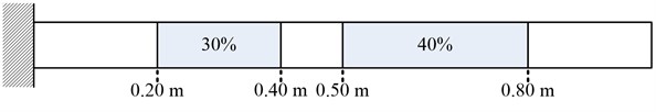
a) Case 1
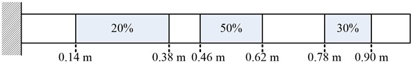
b) Case 2
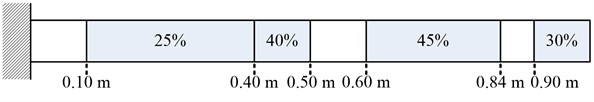
c) Case 3
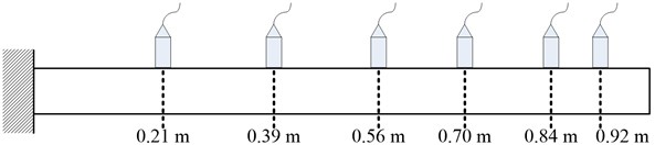
Fig. 3Vibration measured points
3. Test problems
The damage detection in a cantilever beam in Fig. 2 is used as the test problem. Three different situations of this test problem are considered. As shown in the figure, the beam has 2, 3, 4 partially damaged regions, represented by grey areas, in cases 1, 2, and 3, respectively. The damage amount of the damaged regions is shown in the figure. The beam is made from the material of which modulus of elasticity 70.3 GPA and density 2,685 kg/m3. The length (), cross-sectional area (), and moment of inertia () are 1.0 m, 1.82×10⁻⁴ m2, and 1.46×10⁻⁹ m4, respectively. In objective calculation, the beam is equally divided into 100 elements so that there are 200 degrees of freedom – 100 vertical displacements and 100 rotated angles, for the finite element model. In addition, there are 6 measured points at different locations as shown in Fig. 3.
4. Locations and damage factors encoding
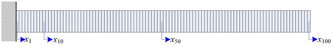
Genetic algorithm (GA), a derivative-free population-based optimization method, is employed as the optimizer in the damage detection. This paper proposes a new encoding, that will be used in GA, for the test problem. The previous works such as [4], [8] employed encoding by damage factor of each element (EDE) in which a decision variable represents damage factor of one divided element. The number of decision variables is directly equal to number of divided elements in the objective calculation. EDE which is benchmarked with the proposed encoding for the test problem is shown in Fig. 4 so that a solution to the problem is represented by a set of 100 variables.
Fig. 4Encoding by damage factor of an element (EDE)
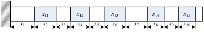
This paper proposes encoding by locations and damage factor (ELD) in which location and damage amount are used. In the test problem, ELD with 5 damaged regions as shown in Fig. 5 is used for all 3 cases. In addition, the number of damaged regions in the encoding must be more than or equal to the number of actual damaged region. A solution is encoded by a set of 15 decision variables. The first 10 variables, -, represent location and length of each damage region occurred in the beam while each of the last 5 variables, -, identify damage amount of each damaged region. The summation of the first 10 decision variable must be less than or equal to one. If the summation the first 10 decision variable of a generated solution is higher than one, these variables of the generated solution have to be changed by dividing with their sum so that the summation of the modified variable is equal to one. Compared to EDE, the number of decision variables is decreased, the search space of ELD is significantly reduced.
Fig. 5Locations and damage factors encoding in 5 damaged regions
5. Results and discussions
The parameter settings of GA are shown in Table 1. Fig. 6 to Fig. 8 illustrate predicted damage factors for all 3 test cases. The figures show that the proposed encoding by locations and damage factor (ELD) is superior to encoding by damage factor of each element (EDE) used in previous works.
Moreover, the predicted damage factors obtained from the proposed ELD are close from the actual damage factors. The experimentally vibration characteristics is assumed to be same as the vibration characteristics of the actual damage numerically calculated by FEM. The values of the weight factors and in Eq. (7) are both equal 1 for all vibration mode . The first 10 vibration modes are considered in the objective calculation so that and in Eq. (7) are all equal to 10.
Fig. 6Predicted damage factors of test case 1
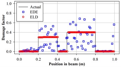
Fig. 7Predicted damage factors of test case 2
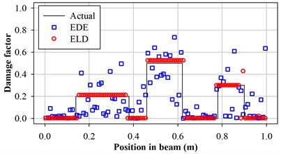
Fig. 8Predicted damage factors of test case 3
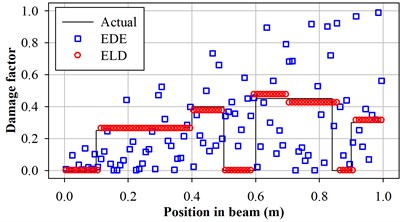
Table 1Parameter settings of GA for the damage detection of all test problems
Parameter | Setting and values |
Chromosome coding | Real-value chromosome with 100 decision variables for EDE, and 15 decision variables for ELD. |
Population size | 30 |
Number of elite individuals | 2 |
Scaling factor [3] | 2.0 |
Selection method | Stochastic universal sampling selection |
Crossover method | Simulated-binary crossover ( 15) [9] with probability = 1.0 |
Mutation method | Variable-wise polynomial mutation ( 20) [10] with probability = 0.03 |
Number of generations used for termination condition | 1.000 |
6. Conclusions
This paper presents the encoding by locations and damage factor (ELD) employing location and damage amount as the decision variables in genetic algorithm. Compared to the previous encoding, EDE, ELD could reduce the number of decision variables to be optimized in GA. The simulation results reveal that GA with ELD can identify the damage occurred in the beam more correctly than GA with EDE. Moreover, the damage predicted by GA with ELD is quite close to the actual damage for all 3 test cases.
References
-
Yang Q. W., Liu J. K. Structural damage identification based on residual force vector. Journal of Sound and Vibration, Vol. 305, Issues 1-2, 2007, p. 298-307.
-
Altunışık A. C., Okur F. Y., Kahya V. Modal parameter identification and vibration based damage detection of a multiple cracked cantilever beam. Engineering Failure Analysis, Vol. 79, 2017, p. 154-170.
-
Goldberg D. E. Genetic Algorithms in Search, Optimization and Machine Learning. Addison-Wesley, USA, 1989.
-
Panigrahi S. K., Chakraverty S., Mishra B. K. Vibration based damage detection in a uniform strength beam using genetic algorithm. Meccanica, Vol. 44, Issue 6, 2009, p. 697-710.
-
Mehrjoo M., Khaji N., Ghafory-Ashtiany M. Application of genetic algorithm in crack detection of beam-like structures using a new cracked Euler-Bernoulli beam element. Applied Soft Computing, Vol. 13, Issue 2, 2013, p. 867-880.
-
Tan Z. X., Thambiratnam D. P., Chan T. H. T., Razakb H. A. Detecting damage in steel beams using modal strain energy based damage index and artificial neural network. Engineering Failure Analysis, Vol. 79, 2017, p. 253-262.
-
Ding Z. H., Huang M., Lu Z. R. Structural damage detection using artificial bee colony algorithm and hybrid search strategy. Swarm and Evolutionary Computation. Vol. 28, 2016, p. 1-13.
-
Boonlong K. Vibration-based damage detection in beams by cooperative coevolutionary genetic algorithm. Advances in Mechanical Engineering, 2015, https://doi.org/10.1155/2014/624949.
-
Deb K., Agrawal R. B. Simulated binary crossover for continuous search space. Complex Systems, Vol. 9, Issue 2, 1995, p. 115-148.
-
Deb K. Mechanical component design using genetic algorithms. Evolutionary Algorithms in Engineering Applications, 1997, p. 495-512.
About this article

This work was financially supported by Faculty of Engineering, Burapha University, Thailand.
