Abstract
The paper deals with basic behaviour and torsional analysis of the engine computational model. This computational model is assembled from own blocks which are created using the basic elements of Simulink software. The paper describes individual blocks and whole assembly of the engine computational model. The simulation of this diesel model was done to verify its function. In conclusion, torsional analysis was carried out.
1. Introduction
Different software is used for development of engine computational model and it is first step of the engine prototype development. However, some parts or internal structure of the prepared computational model cannot be fully modified. Therefore, it is necessary to create a custom engine computation model.
This paper is focused on development of own library with blocks. They describe individual parts of the engine and are created in Simulink software. Then the user can assemble different types of engine construction. For the represent of the real engine, indicated pressure measurement were used. From this data, the torque map is assembled and implement to the engine computational model. The model includes flexible elements; therefore, torsional vibrations can be simulated. The paper also describes an example of a computational model of the eight-cylinder diesel engine. Its simulation of maximum load was compared with measurement of the engine torque and engine power curves. Other simulation describes the torsional vibrations which were evaluated by FFT analysis.
The aim was to create a computational engine model with possibility of real time simulation. In the future, this will allow using of these models for developing and testing of ECU prototypes.
2. Input value of the computational model
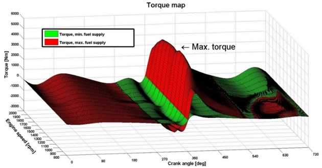
For getting input values of the engine computational model, engine torque and forces acting on the crank mechanism must be calculated. Therefore, input values of the engine computational model are curves of indicated pressure in the engine cylinder. The range of the engine speed, representing pressure curve, is from 800 rpm to 2000 rpm. The cylinder diameter of 120 mm, the engine stroke of 140 mm and the length of the connecting rod of 260 mm were also used for the calculation and the equations are described in [1]. To obtain the whole engine torque map, the individual curves of pressure were recalculated to the torque and were placed to the three-dimensional matrices with the dimensions of 13×720×2 for each cylinder. Some dimensions of the matrices could be different because it depends on the measured data which are available. Here are example matrices used for simulation. First dimension has value of 2, it represents two-dimensional arrays for maximum and minimum fuel supply. The 13 matrix rows contain the engine speed range from 800 rpm to 2000 rpm and the 720 matrix columns represent the crank angle. The matrices of individual cylinder were shifted according to cylinder ignitions. Fig. 1 shows the torque map for a maximum and a minimum fuel supply. Between these statuses, there is range of engine torque which can be used for a drive of powertrain. In the new version of blocks, there is also a possibility of using straight away indicated pressure, because blocks contain equation for calculation of the torque.
Fig. 1Torque map
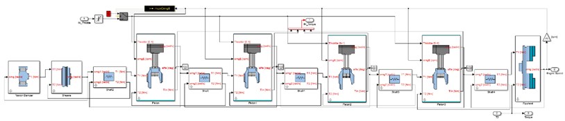
3. Computational model of the engine
The computational engine model is created in Simulink software and uses own library with blocks. For the creation of computational models, the literature [2, 3, 4] was used. This library includes blocks describing the individual parts of engine. Basic principle of blocks is based on flexible elements; therefore, user can simulate torsional vibrations. The engine computational model is represented by a torsional model. The assembly of the computational engine model includes blocks of piston, shaft, flywheel, torsion damper, to name but a few. The computational model is shown in Fig. 2. There is torsional model with seven reduced inertia values and six stiffness blocks between discs. In general, torsional system is described by using Lagrangian method [5]:
where is mass matrix, – damping matrix, – stiffness matrix, – vector of engine torque, – vector of generalised coordinates ( is the angular acceleration, – angular velocity, – angle of deformation) and – time.
Fig. 2Intern blocks of the engine computational model
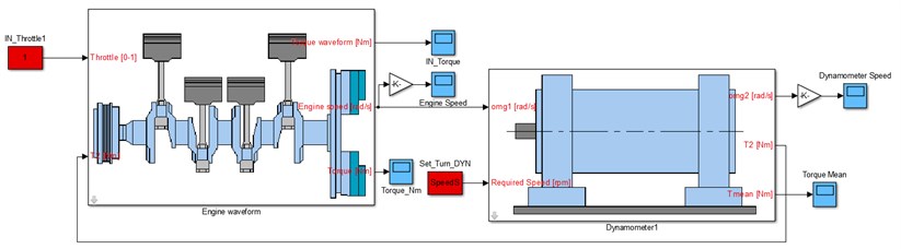
During the simulation, the computational model generates crankshaft angle and engine speed. And the user controls the engine model by an input signal of a throttle pedal. Its value has the range of 0-100 %. These three values determine the value of actual engine torque from torque map. The acquired engine torque is applied on the individual inertia block of the torsional model. These piston blocks are connected together using by flexible blocks, therefore, they affect each other. Then torsional vibration can be simulated. The computational model of the dynamometer is also assembled as a torsional model. Its block is shown in Fig. 3. This dynamometer block generates a torque which counteracts the engine torque to achieve the desired engine speed.
Fig. 3Computational model of engine and dynamometer
4. Simulation
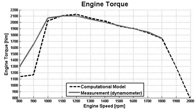
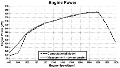
In the simulation, the computational model simulated maximum load of diesel engine. The simulation was divided into several steps. In each step of engine speed, the mean torque was obtained. From these values were created curves of the engine torque and power. Then they were compared with the speed characteristics of the real engine. The results are shown in Fig. 4. The results show that the curves of torque and power are similar in main range of engine speed. In this engine load state, the computational model can be considered working properly. In the future, other simulations will be carried out to verify of other conditions.
Fig. 4Result of the engine speed characteristics
a)
b)
5. Torsional vibration
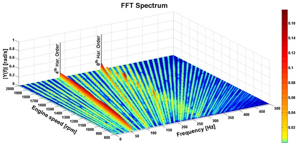
It is an eight-cylinder engine and ignition occur after 90° of the crankshaft. Therefore, it can be assumed that the 4th and 8th harmonics of the engine speed are reflected in torsional vibrations. This frequency can be calculated using the following equation:
where n is the engine speed with the unit rpm and – harmonic order of engine speed. The frequency corresponding to the 4th and 8th harmonic order of the engine speed is calculated at 800 rpm and results are 53.33 Hz and 106.66 Hz.
For the analysis of torsional vibrations, the simulations from the previous chapter were used. Their total torque from each engine cycle was used to evaluate the FFT analysis [6] of the engine speed range from 800 to 2000 rpm. In this FFT spectrum in Fig. 5, the 4th and 8th harmonic order of the engine speed are clearly visible. It corresponds to the calculations in Eq. (2). These harmonic orders can excite torsional system of the engine or the vehicle powertrain. This occurs when the actual torsional frequency is equal to the harmonic order of the engine speed. In the graph in Fig. 5, there is very little visible transition over the 2nd own engine frequency (282.73 Hz) because the torsional vibration is damped. Results of torsional vibration analyses shows that the model works properly and can be used for analyses of other engines or excitation of the whole virtual vehicle powertrain.
Fig. 5FFT spectrum of the engine computational model
6. Conclusions
The aim was to assemble the computational engine model which describes the functions of the real engine, can be simulated in the real time and can be used for analyse of the torsional vibration. The computational model was assembled from own library with blocks. They represent individual parts of the engine.
The results of engine speed characteristics in the first simulation were compared to the real engine and the virtual engine can be used for a simulation with maximum load of an engine. However, other simulations must be done to verify other operating modes of the engine. The results of the torsional vibration analysis show generated harmonic order of the engine speed and it correspond with theoretical assumptions. In the future, measurement of torsional vibration must be done to verify of results.
This engine computational model can be also used for real-time simulations in the Hardware in the Loop systems. It is important for future development and testing of ECU prototypes.
References
-
Heisler H. Advanced Engine Technology. 1st Edition. Arnold, Oxford, 2002.
-
Gillespie T.D. Fundamentals of Vehicle Dynamics. Society of Automotive Engineers, Warrendale 1992.
-
Budynas R. G. Shigley’s Mechanical Engineering Design. McGraw-Hill, New York, 2006.
-
Kučera P. Mechatronic Approach to Vehicle Dynamics. Doctoral Thesis, BUT Brno. 2015
-
Nestorides E. J. A Handbook on Torsional Vibration. Cambridge University Press¸ Cambridge, 1958.
-
Tůma J. Vehicle Gearbox Noise and Vibration. Wiley, Chichester, 2014.
About this article

This work is an output of the internal BUT Research Project Reg. No. FSI-S-17-4104.
