Abstract
Especially, with the advancement of technology, mechanical parts need to be designed to be lighter and more durable. In the industry, gears are the most common power transmission equipment, and for this equipment, increasing durability and rigidity has an essential importance. During power transmission, undesired vibration and noise arise in gear systems. In addition to gear design, gearbox housing design is also essential to reduce the radiation of undesired structure-borne noise and vibration. In order to reduce noise and vibration levels, some modifications are frequently used on gearbox housings. In this study, three different gearbox housing designs (basic, cross and cellular) are formed and analysed by using ANSYS® software. The design alternatives for housings have been formed inside of the structure as different quantities of longitudinal and transverse stiffeners. In addition, all the external dimensions and the mass of these three housing designs are equal in order to observe just vibration and noise reduction. Fast Fourier Transform (FFT), statistical properties of vibration signals and sound levels of the gearbox have used for comparisons to determine which gearbox have better vibration and sound levels.
Highlights
- The mass and the external dimensions of the gearbox housings are kept constant for the three designs.
- According to the statistical parameters, the cross model and the cellular model have better results than the basic model.
- The cellular model has the lowest sound pressure level.
- The FFT result of the cellular model has a lower vibration amplitude than the other two models.
1. Introduction
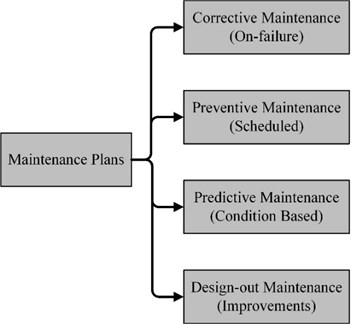
Gearboxes are one of the most commonly used mechanical power transmission systems in the industry. They use two gears or gear trains to provide speed and torque transmission from a rotating power source to another device in desired ratios and high efficiency [1]. In gear systems, the vibration and noise generated at the gear mesh transmits to the gearbox housing through the shafts and bearings, and this causes structure-borne noise [2-5]. Low vibration and noise are desired for mechanical power transmission systems, because excessive vibration on power transmission systems may cause damage to connected machine, damage to product quality, lead to degradation in plant working conditions, lead to consuming excessive power, reduce machine’s lifetime, and finally knock it out of service and halt plant production. Therefore, vibration and noise are widely accepted as a measure of the total quality of machines. Maintenance methods have been developed in order to maintain the operation of the established system without interruption. These maintenance plans are illustrated in Fig. 1. In these maintenance strategies, design-out maintenance (DOM) has more applications recently and it ensures sustainable production and economic contributions in the industry [6]. Design-out maintenance also known as eliminative maintenance [7] is to improve the design of machine in order to minimize effect of failures as well as to eliminate the cause of maintenance such as vibration and noise [8].
Redesigning and helpful modifications on machine can provide increase the systems reliability and machine performance. Therefore, in DOM, maintenance engineers work in close cooperation with design engineer [9]. The DOM has attracted much attention recently due to the increased use of structural analysis programs. Because of excessive costs associated with testing of real equipment, researches into structural and mechanical systems are often conducted with the aid of numerical models and simulations. For modelling and simulations, structural analysis programs such as SolidWorks® and ANSYS® are often demanded and used extensively in the pre-production stage for design and analysis. These programs provide a decrease in time and effort needed for a better quality of production. After numerical structural analysis on these programs, the measurements and verification analyses are performed on the test product. The final product is produced at the final stage.
During the power transmission, mechanical vibration also causes environmental noise. The importance of reduction of vibration and noise generated from gears has grown in recent years. One of the possible ways to reduce this noise is to decrease the vibration level in the source of the sound emitted. An important factor causing vibration and noise of the housing is dynamic forces evoked during the meshing between gears. However, the noise and vibration of gearboxes are emitted mainly by its housing [10]. For this reason, the design of a gearbox is critical for the noise and vibration. In order to hold these structural effects as low as possible, different gear housing designs have been investigated. Vibration and noise are broadly accepted as a measure of qualities of the gearboxes and reduction of them are demanded.
Fig. 1Maintenance plans
There are some researches carried out to reduce vibration in gear systems by using improved housing design. Inoue and Yamanaka investigated the influence of stiffened plate construction to reduce the noise as well as the vibration. In their research, they researched the rib stiffener layout and most effective positions of stiffeners in order to reduce the vibration [11]. Kumar et al. tackled with the failure problems of transmission housing or gearbox which were main problems for vehicle manufacturers. They found that noise and vibration were the main reason. So as to reduce vibration and noise levels, they analyzed the natural frequencies and mode shapes of housings by ANSYS® [12]. Lazarz and Perun presented a paper including the results of numerical and experimental studies on the influence of selected factors on the dynamic forces and vibration of the gearboxes. The study was performed using a dynamic model of a test stand with the gears operating in the circulating power system [13]. Folega et al. studied an experimental and theoretical modal analysis of structural solutions of housings gear. The modal analysis of examined gearbox housing versions enabled to estimate the influence of made ribbing modifications on form and frequency of vibrations [14, 15]. The aim of all these studies is to contribute to the production of better-quality mechanical equipment with low vibration and noise level during operation.
Mechanical improvements on structures could be accomplished in two ways; one is producing better quality products, while keeping mass constant and the second one is achieving a predetermined quality by reducing in mass. In this study, structural improvements have been researched for equiponderant housings [16]. The purpose which differentiates this study from others is to achieve vibration and noise reduction with inner stiffeners and webs for each gearbox housing designs, while the mass of gearbox housings keeps constant. Furthermore, modifications on gearbox housing are applied to the inner of gearboxes, unlike the other studies. Aims of this research can be summarized as reducing the vibration and noise levels without increasing the mass, analysing effects of the inner stiffeners on housing designs, and identifying the natural frequency influence on vibration levels.
2. Mechanical design and analysis
2.1. Mechanical design
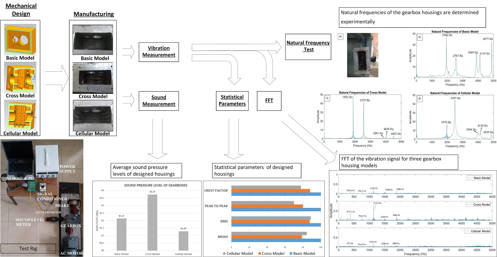
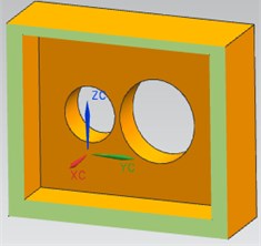
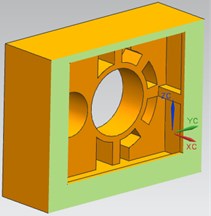
In this study, three different gearbox housing designs (basic, cross and cellular) are investigated. All gearbox housings have been designed by keeping the same transfer ratio, the same external size and the same mass. The outer dimensions of these three gearbox housings are 205×160×140 mm, which is fixed for all designs. The total mass of gearbox housings is equal and about 5.2 kg; range of ±10 gr. The design differences for housings have been established inside of the structure as usage of webs and stiffeners. So as to preserve the mass, wall thicknesses is changed. All designed housings have been analysed through the modal analysis of ANSYS in order to determine natural frequencies. For the experiment, three different gearbox housings (basic, cross and cellular) are produced. The basic model of gearbox housing has no stiffener, no longitudinal and transverse webs. Housing solid models are shown in Fig. 2-4. The basic model of gearbox housing can be shown in Fig. 2.
Fig. 2The basic model
a)
b)
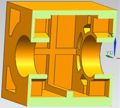
In order to determine design effects on gearbox vibration, longitudinal and transverse stiffeners are located to the centre line of the side walls and the transverse stiffener is located to the base wall, as shown in Fig. 3. In addition, longitudinal webs are located around bearing races in order to support bearings and reduce vibration tendency. This second model is called as a cross because of the appearance of stiffeners. The mass, changed due to stiffeners and webs, is kept the same by changing wall thickness in order to compare with the basic model more reliably.
Fig. 3The cross model
a)
b)
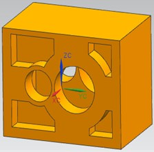
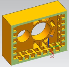
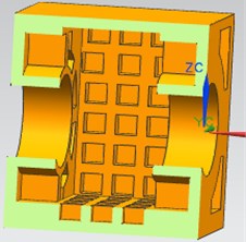
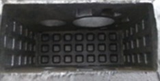
For the third model called cellular, longitudinal and transverse webs are located to both side and base walls in order to strengthen the body, as shown in Fig. 4. The mass, decreased due to webs, is increased by thickened walls in order to maintain constant mass in comparison with the basic model.
Fig. 4The cellular model
a)
b)
2.2. Natural frequency analysis
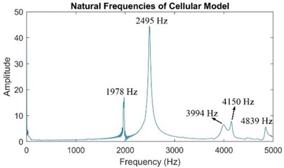
Three housings were designed to enhance vibration tendency with the same external size and gear ratios. Natural frequency analyses of structures were executed by ANSYS as free-free boundary condition and results are shown in Table 1. In order to verify the results of ANSYS, natural frequencies are obtained from the free vibration response of the models initiated by the impact test. In the experimental measurements, the free-free boundary condition is used for gearbox housing models. The results of the natural frequency experiment are also given in Table 1. According to Table 1, the first natural frequency of the cellular model is higher than that of the basic and cross model.
Table 1Natural frequencies of the gearbox housing models obtained from the ANSYS and experiment
BASIC Model | CROSS Model | CELLULAR Model | ||||||
ANSYS (Hz) | Experiment (Hz) | Difference (%) | ANSYS (Hz) | Experiment (Hz) | Difference (%) | ANSYS (Hz) | Experiment (Hz) | Difference (%) |
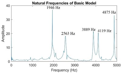
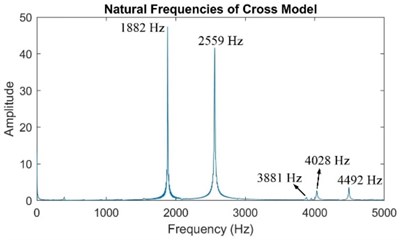
1986.6 | 1946 | –2.04 | 1962.8 | 1882 | –4.11 | 2066 | 1978 | –4.25 |
2773.5 | 2563 | –7.58 | 2911.9 | 2559 | –12.11 | 2904.8 | 2495 | –14.1 |
3928.4 | 3889 | -1 | 3797.9 | 3881 | 2.1 | 3994.9 | 3994 | –0.02 |
4160.5 | 4119 | –0.99 | 3852.5 | 4028 | 4.55 | 4290.1 | 4150 | –3.26 |
4820.3 | 4875 | 1.13 | 4347 | 4492 | 3.31 | 4623 | 4839 | 4.67 |
Natural frequencies tested experimentally of the manufactured gearbox housing are shown in Fig. 5. The cellular model of the gearbox housing is given in Fig. 5(a) as an example of the natural frequency experiment. The natural frequencies of the basic, cross and cellular models can be shown in Fig. 5(b)-(d), respectively. The differences between the results of ANSYS models and the results of the experiments are given in Table 1 as a comparison of results. It can be seen from Table 1 that the results are very similar.
3. Manufacturing and experimental setup
3.1. Manufacturing of gear housings
Casting model was produced for all three gearbox housings. Since there were no differences between external dimensions of gearbox housings, one model was produced for all the three designated gearboxes and three core boxes were produced for each design because of inner differences of the housings. Gearbox housings were produced by the method of aluminium gravity casting and the type of aluminium is Etial-150 (AlSi12Cu2Fe). Housing models are shown in Fig. 6.
After casting operation, all gearbox housings were machined for their bearing house in the same manner and accuracy. Identical bearings were supplied. For each gearbox, one pinion helical gear and one wheel helical gear are used. Pinion gears and wheel gears having 37 and 15 teeth, respectively were produced with the same accuracy in the same production line in order not to affect vibration analysis. Gear ratio of the gearboxes is 2.47. Gears were made by 8620 case hardening steel (21NiCrMo2) and hardened to the value of 58-60HRC. Shafts of the wheel gears were produced in the same manner.
Fig. 5Natural frequencies tested experimentally of the manufactured gearbox housing
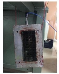
a)
b)
c)
d)
Fig. 6Model of the gear housings

a) Basic model

b) Cross model
c) Cellular model
3.2. The experimental setup
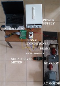
The gearbox is driven by a 1.5 kW, 3000 rpm three-phase AC motor and a variable speed controller was used to drive the motor-shaft-gearbox. The capacity of electromagnetic brake is 30 Nm, which is used in the system as a load for gearbox. The experimental setup is shown in Fig. 7.
The helical gears generate the vibration signals and these signals are acquired using two PCB 352A76 type accelerometers, whose frequency range is 5-16000 Hz and its sensitivity 1 mV/g. The accelerometer was mounted to the side wall of gearbox housings. The noise signals are acquired by sound level meter (Extech instruments, SDL600), as shown in Fig. 7. A PCB 480C02 type signal conditioner has been used to optimize accelerometer outputs. The position of the input shaft has been indicated using a 5V DC ME4 S12L-PA type inductive sensor which produces a single pulse per rotation of the pinion gear. This sensor has been used for the synchronous time domain averaging (TSA) of the gear vibration signal. Analog to digital converter was used to transform signals. In this work NI DAQ Card (which is a trademark of National Instrument Data Acquisition Card) 6036E has been used as an analog to digital converter (ADC). All the signals acquired from accelerometers have been sampled at a determined rate and have been recorded on a computer using NI DAQ Card and Lab VIEW 7.0 software.
Fig. 7Experimental setup
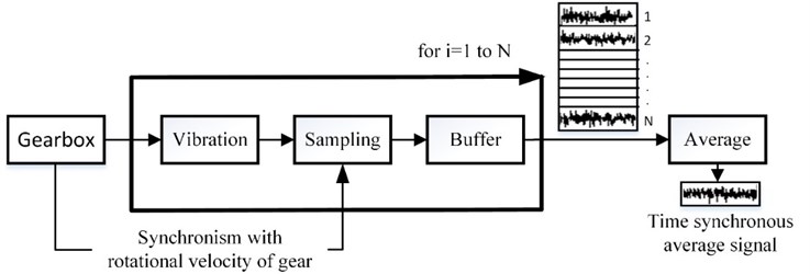
TSA is applied to the raw signal to eliminate some signal components which may consist of electrical and mechanical noise. Measurement of all samples starts at the same exact point and samples are synchronous with rotational velocity [17]. The vibration samples are averaged in time, employing periodicity with gear shaft rotating speed. The averaged vibration signals are obtained for every 10 turns of the input pinion gear. A simplified block diagram of TSA used in this study is shown in Fig. 8.
Fig. 8A simplified block diagram of TSA for this study
4. Results
For this experimental study, the speed of the motor was set to 1500 rpm. The vibration signals acquired from accelerometer and pulse signals acquired from the inductive sensor were sampled at 10 kHz and stored on a computer. The raw vibration data was acquired for 60 second that is equal to 1500 pinion gear rotation and 607 wheel gear rotation, owing to gear ratio.
Fig. 9. illustrates spectrum representation of averaged gear vibration for three gearbox housings for 0 to 5000 Hz. The rotating frequency of the gear input shaft can be seen as 25 Hz especially, in the basic and cross model figure. Amplitudes of frequencies are generally lower for the cellular model than the other models. Also, peaks are seen in the frequency spectrums of the three-gear models for 377 Hz, 754 Hz, 1131 Hz, 1508 Hz and 1885 Hz, which are gear mesh frequency (GMF) and its harmonics. The cellular model does not contain any other significant peaks except GMF, as shown in Fig. 9. Also, the amplitude of frequency increases steadily in the higher frequency range.
Fig. 9FFT of the vibration signal for three gearbox housing models (0-5000 Hz)
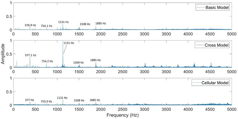
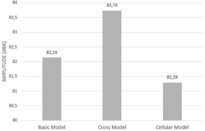
Fig. 10 compares the averaged sound level of gearbox housings. When the noise level of the running gearboxes is measured, there are close results for three gearbox housings. The noise level of the experimental test area is 35 dBA. The cross model gave a higher sound level than the basic model. However, the noise generated by the cellular model during operation is considerably lower than that of the other two gearbox housings.
Fig. 10Average sound pressure levels of designed housings
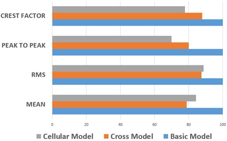
Statistical properties can be subsidiary and informative about the improvement of the vibration tendency of gearbox housings. In this study, statistical properties of vibration signal as mean, root mean square (RMS), peak to peak and crest factor is used for explaining gearbox housing comparisons. According to designed gearbox housings, the results of these statistical properties are given in Fig. 11.
According to the results of the statistical parameter, the cross model shows minimum mean and RMS acceleration during the experiment. RMS and mean results for the cellular and cross models are very close to each other. On the other hand, the cellular model gives better results on peak to peak and crest factor results. Consequently, the cross and cellular designs decrease the vibration on gearboxes and their results are sharply better than the basic model.
Fig. 11Statistical parameters levels of designed housings
5. Conclusions
The scope of this study is gearbox vibration and noise reduction. In order to reduce vibration levels, some mechanical improvements were implemented to gearbox housings.
According to the experimental results, when the statistical values of the vibration signal of the cross model and the cellular model are examined, it is seen that they have better results than the basic model. According to the sound level results, the cross model has high sound level even compared to the basic model, but the cellular model seems to have better sound characteristics. Moreover, the cellular model design for the FFT results shows more successful results than the other two models with low vibration amplitude. Therefore, it is obvious that adding stiffeners is better than applied webs in order to reduce the vibration of gearbox housings. Consequently, vibration and noise reduction have been achieved without increasing the mass. These implementations contribute to design more rigid and durable parts.
As a future study, geometrical optimization of the considered gearbox housings can be performed in order to find the best combination of both the dimensions of the housing and the type of inner stiffeners. For this purpose, some dimensions can be selected as design variables and they may be varied into predefined limits related to the useful workspace and the gearing configuration. Also, shape and number of the inner stiffeners can be assigned as design variables to analyse the possible different structural configurations. After specifying the design variables, limits on the static and/or dynamic behaviour of the structure (maximum stress and displacement value, natural frequency etc.) can be assigned as the design constraints. In this study, the mass of the gearbox housing has been kept constant for considered housing models, but minimization of the mass can be chosen as the goal of the optimization study in order to obtain the optimum geometry.
References
-
Ozturk H. Gearbox Health Monitoring and Fault Detection Using Vibration Analysis. Ph.D. Thesis, Graduate School of Natural and Applied Sciences of Dokuz Eylul University, Turkey, 2006.
-
Rautert J., Kollmann F. G. Computer simulation of dynamic forces in helical and bevel gears. Proceedings of the International Power Transmission and Gearing Conference, 1989, p. 435-445.
-
Choy F. K., Ruan Y. F., Zakrajsek J., Oswald F. B. Modal simulation of gear box vibration with experimental correlation. Journal of Propulsion and Power, Vol. 9, Issue 2, 1993, p. 301-306.
-
Krishnaswamy K., Rajamani R., Woo J. J., Cho Y. M. Structural vibration control for broadband noise attenuation in enclosures. Journal of Mechanical Science and Technology, Vol. 19, Issue 7, 2005, p. 1414-1423.
-
Gao W., Wang W. L., Liu Y. A modified adaptive filtering algorithm with online secondary path identification used for suppressing gearbox vibration. Journal of Mechanical Science and Technology, Vol. 30, Issue 11, 2016, p. 4833-4843.
-
Tumer I., Stone Y., Robert B. Mapping function to failure mode during component development. Research in Engineering Design, Vol. 14, Issue 1, 2003, p. 25-33.
-
Gopalakrishnan P., Banerji A. K. Maintenance and Spare Parts Management. PHI Learning Pvt. Ltd., 2013.
-
Waeyenbergh G., Pintelon L. A framework for maintenance concept development. International Journal of Production Economics, Vol. 77, Issues 3, 2002, p. 299-313.
-
Jain A. K. Influence of modification of design out maintenance and design out information system for maintenance cost control and a lucrative business (with case study). International Journal of Engineering Trends and Technology, Vol. 4, Issue 1, 2013, p. 1-9.
-
Figlus T., Wilk A. Application of FEM method in reduction of gear transmission housing vibration. Journal of KONES, Vol. 16, Issue 2, 2009, p. 97-102.
-
Inoue K., Yamanaka M., Kihara M. Optimum stiffener layout for the reduction of vibration and noise of gearbox housing. Transactions-American Society of Mechanical Engineers Journal of Mechanical Design, Vol. 124, Issue 3, 2002, p. 518-523.
-
Kumar A., Jaiswal H., Pandey A., Patil P. P. Free vibration analysis of truck transmission housing based on FEA. Procedia Materials Science, Vol. 6, 2014, p. 1588-1592.
-
Łazarz B., Peruń G. Influence of construction factors on the vibrational activity of the gearing. Transport Problems, Vol. 7, Issue 2, 2012, p. 95-102.
-
Folęga P., Burdzik R., Konieczny L., Wieczorek A. Influence of housing ribbing modification on frequencies and shapes of vibration. Journal of Measurements in Engineering, Vol. 1, Issue 3, 2013, p. 159-163.
-
Folęga P., Burdzik R., Wojnar G. The optimization of the ribbing of gear transmission housing used in transportation machines. Journal of Vibroengineering, Vol. 18, Issue 4, 2016, p. 2372-2383.
-
Dalbicer C. Experimental Analyses of Gearbox Housing Design. M.Sc. Thesis, Graduate School of Natural and Applied Sciences of Dokuz Eylul University, Turkey, 2016.
-
Hizarci B., Ümütlü R. C., Kiral Z., Ozturk H. Smart condition monitoring of worm gearboxes. Inter-Noise and Noise-Con Congress and Conference Proceedings, 2016.
Cited by
About this article

