Abstract
All the current sound field separation methods based on particle velocity are apply measurement surfaces or a single measurement surface with pressure-velocity. In order to acquire less measurement data and efficient calculation, a sound field separation method with single holographic surface based on particle velocity is proposed. According to the principle of equivalent sources near-field acoustical holography technique, this method can separate directly the sound filed information radiated by target source from coherent sound fields. Numerical simulation analyzed the results with different frequencies and signal-to-noise ratio (SNR). The results show that this method can separate the coherent sources accurately and efficiently.
Highlights
- Particle velocity separation Basic theory
- Comparative particle theoretical vibration speed and separation vibration speed
- Effect of SNRs on separation error
1. Introduction
Near-field acoustical holography (NAH) is a technique for reproducing sound field information [1, 2], because this algorithm has a great advantage in noise source identification and positioning, which gets a fast application in engineering. Sound field separation technology based on NAH requires that the traditional NAH measurement surface must be located on the same side of the sound sources.
At present, the main sound field separation methods, contain space-based Fourier transform [3, 4], SONAH method [5, 6], boundary element method [7, 8], and equivalent source method [9]. There are two main data input methods for sound field separation based on the equivalent source method [10], which is the sound pressure based on double measurement surface and sound pressure – vibration speed input method based on a single measurement surface. Zhang et al. [11] proposed an improved sound field separation formula for eliminating singular values and a statistical optimal single-side sound field separation method. Mao et al. [12] used a single measurement surface to separate directly the coherent sources based on sound pressure.
This paper uses the input method of particle velocity collected measured on a single measurement surface. The source is equivalent to some point sources on a virtual sphere using the error of the measurement data. There are different transfer functions between the equivalent source point and different points in space, and then we can obtain a single measurement surface sound field separation formula based on vibration velocity.
2. Basic theory. Particle velocity separation
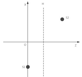
The basic principle of the equivalent source method is to place some equivalent sound sources inside the vibrating body. Using the superposition of these equivalent sound sources to generate sound field, could replace the original sound field radiated by the vibrating body. According to the Helmholtz equation, Fig. 1 shows the location of the target sound , interference sound and holographic surface.
There is on one side of the measuring surface and a single measurement is used to separate the sound field, the false sound source may interfere with the separation result when the sound source is reconstructed. In order to remove the error caused by the interference sound source, put some simple equivalent sources on the virtual sphere evenly, and establish a transfer function matrix between virtual equivalent sources and measurement points. The measurement vibration speed can be expressed by:
where is the theoretical vibration speed produced by , is the theoretical vibration speed produced by , is the measurement error formed by , and is the measurement error formed by .
Fig. 1Sound field locations of sources and measurement surface
Reconstruction of the vibration speed can be expressed by:
where is the transfer matrix from the equivalent source on to the holographic surface . is the transfer matrix from the equivalent source on to the surface . In the same way, the vibration speed produced by on the surface can be approximated by equivalent sources placed on the fictitious surface :
Because the errors and are smaller relative to the signal, the regularization method is used to reduce the influence of the error when the theoretical vibration velocity is calculated. We can obtain the approximate representation as follows:
By Eq. (1) we can obtain the following equation:
Combining Eqs. (5) and (6), we can obtain the following equation:
By Eq. (1) we can obtain the following equation:
Combining Eqs. (7) and (8), we can obtain the following equation:
By Eq. (4) into the right part of Eq. (9), we can obtain an approximate equation:
where make the simplification Eq. (10), we can obtain the vibration velocity approximate equation:
where is the identity matrix.
It is obvious that, with the above-mentioned method, the particle velocity radiated by the can be separated from the coherent sound field.
3. Simulation analysis
Fig. 1 shows the locations of the sound field. Two pulsating sources are placed on either side of the holographic surface. Target source and interference source coordinates are located at (-0.15, 0, 0) m and (0.15, 0, 0.2) m, respectively. All the sound sources all have the same radius of 0.01m, the vibration speed of sound sources is 0.25 m/s. putting the virtual ball inside the sound source, and the virtual sphere radius is 0.008 m. the virtual sphere is divided into equal grids, and the equivalent sound source is placed at the grid node, there are ninety-two equivalent sources in both pulsating sources. The holographic plane is located at 0.08 m along the horizontal () directions. The hologram size is direction 0.49 meters, 0.49 meters in the direction, using 8 sensors arrays per row and per column, the grid space was 0.07m along the horizontal () and vertical () directions. During numerical simulation, white Gaussian noise with 30 dB SNR is added to the theoretical value. The mixed sound pressure measured by this holographic plane includes the sound pressure produced by the target sound source and the interference sound source and their respective errors. We use the algorithm introduced in this paper to separate the sound field information of the target sound source from the interference sound source and the measurement error.
The separated error level can be expressed by:
where is the theoretical value of particle velocity radiated by the target sound source on the measuring surface, and is the calculated value.
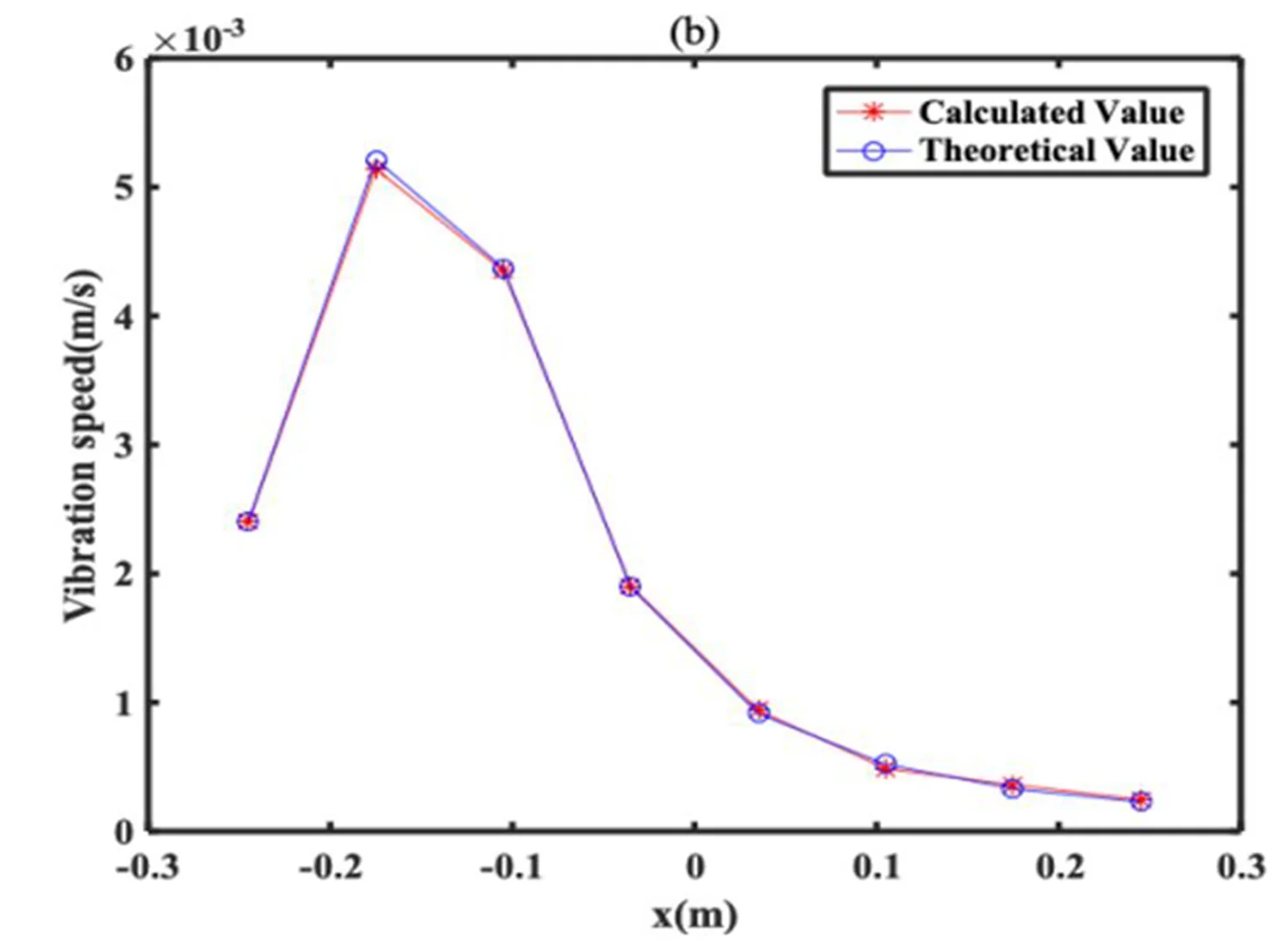
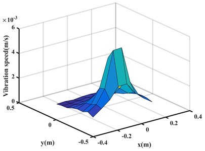
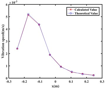
The three-dimensional map is shown in Fig. 2. Fig. 2(a) shows the target sound calculated value in the holographic surface; Fig. 2(b) shows a two-dimensional sectional view of the theoretical value and the calculated value in the plane, where – represents the theoretical value, - - + -- represents the calculated value.
Fig. 2(a) shows a three-dimensional graph of the vibration velocity of target source, which was obtained by the calculated using this algorithm; Fig. 2(b) shows a two-dimensional diagram of the theoretical and the separated velocity, from where it can be seen that the errors between these two values are very small. Here, the separation error is Leer = –33.35 dB, which is calculated by Eq. (12). It is obvious that, such field separation method is effective and accurate.
Fig. 2Vibration velocity measured on the holographic plane at 1000 Hz: a) calculated value, b) comparison chart
a)
b)
Fig. 3Calculation errors at different frequencies
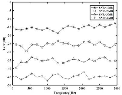
After demonstrating that this separation method is feasible and accurate, in order to further verify the performances of this sound field separation method, we continue to study the error produced by this method at different SNRs (from 10 to 40 dB) and different frequencies (from 100 to 3000 Hz). The results of the analysis are shown in Fig. 3. Obviously, the method based on the single-measurement surface vibration velocity has a good separation effect at different frequencies. It further proved the validity of the proposed separation method.
4. Conclusions
The single holographic surface sound field separation method is based on wave superposition, according to the vibration velocity information on the holographic surface to build the sound field separation formula. Numerical simulation analyzes the process of sound field separation with a single holographic surface from the 100 Hz to 3000 Hz. It is verified that this method is effective and accurate to separate the target source information from coherent sources, and it can be used in a relatively wide frequency range.
References
-
Williams E. G., Maynard J. D., Skudrzyk E. Sound source reconstructions using a microphone array. Journal of the Acoustical Society of America, Vol. 68, Issue 1, 1980, p. 340-344.
-
Maynard J. D., Williams E. G., Lee Y. Near-field acoustic holography: I. Theory of generalized holography and the development of NAH. Journal of the Acoustical Society of America, Vol. 78, Issue 4, 1985, p. 1395-1413.
-
Totaro N., Vigoureux D., Leclère Q., et al. Sound fields separation and reconstruction of irregularly shaped sources. Journal of Sound and Vibration, Vol. 336, 2015, p. 62-81.
-
Sun Y. H., Xiang Y., Wang Y. J. Comparison of regularization methods of near-field acoustic holography based on Fourier transform-source simulation technique. Journal of Guangxi University of Science and Technology, 2014.
-
Li W. B. The principle of statistically optimal planar near-field acoustical holography and the sound field separation technique. Acta Physica Sinica, Vol. 54, Issue 3, 2005, p. 1253-1260.
-
Li W., Chen J. Study on statistically optimal cylindrical near-field acoustical holography. Chinese Journal of Mechanical Engineering, Vol. 41, Issue 4, 2005, p. 123-127.
-
Bai M. R. Application of BEM-based acoustic holography to radiation analysis of sound sources with arbitrarily shaped geometries. Journal of the Acoustical Society of America, Vol. 92, Issue 1, 1992, p. 533-549.
-
Veronesi W. A., Maynard J. D. Digital holographic reconstruction of sources with arbitrarily shaped surfaces. Journal of the Acoustical Society of America, Vol. 85, Issue 2, 1989, p. 588-598.
-
He Y., Wei X., Xu Z., et al. Sound field separation of coherent sources using double plane measurements based on equivalent source method. Chinese Journal of Scientific Instrument, Vol. 35, Issue 9, 2014, p. 2109-2115.
-
Bi Chuan Xing, Zhang Yong Bin, Xu Liang, et al. Separation of sound field based on the measurement of two-sided particle velocity. Journal of Acoustics, Vol. 6, 2010, p. 653-658.
-
Zhang Yong Bin Near-Field Acoustic Holography Based on Equivalent Source Method and Particle Velocity Measurement. Hefei University of Technology, 2010.
-
Mao Jin, Xu Zhong Ming, Li Shu, et al. Direct sound field separation method for single holographic surface. Journal of Acoustics, Vol. 1, 2017, p. 115-121.
About this article

Project supported by the National Natural Science Foundation Youth Fund (Grant No. 61701397, 51705419), and supported by the Natural Science Basic Research Plan in the Shaanxi Province of China (No. 2017JQ5011).
