Abstract
In order to study the effect of different inlet velocity on the polishing quality of abrasive flow machining, this paper takes the variable diameter pipe as an example. The fluid dynamic pressure and total energy of abrasive particles under coupling field with different inlet velocities were carried out by using computational fluid dynamics software. The results of numerical analysis show that the polishing quality becomes better with the increase of the inlet velocity. At the same inlet velocity, the smaller the pipe diameter is, the higher the polishing quality will be. Therefore, the optimum inlet velocity can be selected by numerical simulation according to the size of the aperture of workpiece in the actual processing, which can provide technical support for the production.
1. Introduction
The rapid development of engineering technology, machining has progressed from rough machining to precision ultra-precision machining, more and more ultra-precision machining has emerged [1, 2], the abrasive flow polishing is a processing technology in the field of ultra-precision machining. It uses semi-solid abrasive to make the abrasive move to and from on the surface of the machined parts under certain pressure, which can polish all kinds of cavity, cross aperture and edge of the parts [3-5]. Variable diameter pipe parts are widely used in aerospace, automobile, mechanical processing and other industrial production. Due to the special structure of variable diameter pipe parts, the traditional processing method is difficult to perform an effective finishing process on its inner surface [6, 7]. Therefore, the study of abrasive flow polishing technology has extremely important engineering application.
2. Geometric model
2.1. Creation of physical model
The Fig. 1 is the three-dimensional modeling, which was carried out according to the actual geometric model.
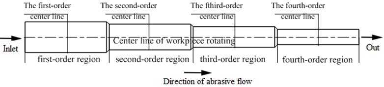
In order to facilitate the analysis of the numerical variation trend, the variable diameter pipe is divided into four region, which is shown in the Fig. 2. The length of the variable diameter pipe is 12.7 mm, which is divided into four parts and the diameter of each order is1.2 mm, 1.0 mm, 0.8 mm and 0.6 mm. The first-order center line, the second-order center line, the third-order center line and the fourth-order center line are located at the transverse center of each region respectively. The center line of workpiece rotating is defined as the origin of the center line of each region and above the center line is positive and below is negative.
Fig. 1Three-dimensional model

Fig. 2The division area of flow passage
3. Parameter setting of the model
According to structure characteristics of the variable diameter pipe and the size of the abrasive particle, the length of time step is 2E-7s, the total time of numerical simulation is 1 s and the command of Track Collision is opened. Momentum Under-relaxation is set to 0.7, which makes it easier to converge. In the simulation process, the k-epsilon (2 eqn) model is selected to solve, the Standard Wall Functions in near-wall Treatment is selected. The wall is regard as the solid wall without slip.
4. Analysis of simulation results
The abrasive particle size was set as 300 mesh (48 um) and the abrasive concentration was 10 %. The inlet velocity was selected as 30 m/s, 35 m/s, 40 m/s and 45 m/s for numerical simulation analysis. The fluid dynamic pressure and total energy of abrasive particles under coupling field with different inlet velocities were obtained, as shown in Fig. 3.
From Fig. 3(a) to Fig. 3(d), it can be seen that the inlet velocity will directly affect the distribution of fluid dynamic pressure and total energy of abrasive particles. With the abrasive flow into the cavity, the first-order region has the smallest dynamic pressure and total energy of abrasive particles, while the fourth-order region has the largest dynamic pressure and total energy of abrasive particles. The larger the total energy of abrasive particles, the more violent collision on the wall surface so that the fourth-order region polishing quality is the best.
In order to analyze the numerical variation trend of each order region accurately, the fluid dynamic pressure with inlet velocity of 45 m/s was used for numerical analysis, and the data of every order center line of the workpiece was analyzed.
The histogram of fluid dynamic pressure at the center line of different regions were obtained as shown in Fig. 4.
From Fig. 4(a) to Fig. 4(d), it can be seen that the variation trend of dynamic pressure in each order is similar, but the numbers of the dynamic pressure increases with the decrease of the aperture. As shown in Fig. 4(e), the fluid dynamic pressure is the smallest at the beginning of each stage and then gradually increases. In the actual processing, the appropriate increase of the dynamic pressure is conducive to the workpiece surface polishing.
Fig. 3Coupling field nephogram of fluid dynamic pressure and total energy of abrasive particles under different Inlet velocity
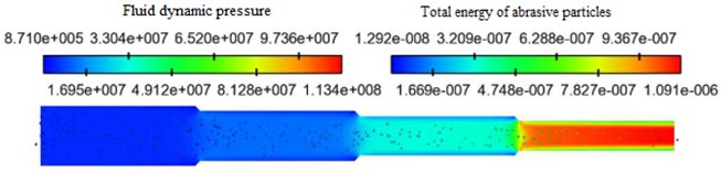
a) Inlet velocity 30 m/s
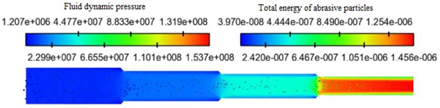
b) Inlet velocity 35 m/s
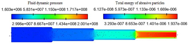
c) Inlet velocity 40 m/s
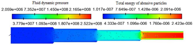
d) Inlet velocity 45 m/s
Fig. 4The histogram of fluid dynamic pressure at the center line of different regions
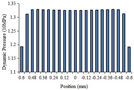
a) The first-order center line
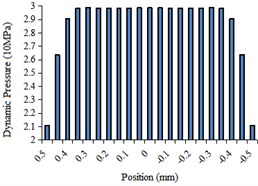
b) The second-order center line
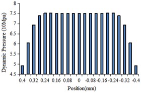
c) The third-order center line
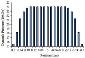
d) The fourth-order center line
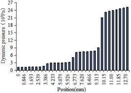
e) The center line of workpiece rotating
In order to better analyze the influence of the fluid dynamic pressure near the wall surface of workpiece on the abrasive flow polishing, the fluid dynamic pressure near the wall of the workpiece in different regions of the pipe was selected for numerical analysis, and the distribution table of the fluid dynamic pressure near the wall of the workpiece under different inlet velocities was obtained, as shown in Table 1.
Table 1Fluid dynamic pressure distribution table of workpiece near wall surface under different inlet velocity
Inlet velocity (m/s) | Fluid dynamic pressure (10 MPa) | |||
The first-order region | The second-order region | The third-order region | The fourth-order region | |
30 | 0.108 | 0.483 | 0.996 | 11.001 |
35 | 0.394 | 0.981 | 1.365 | 12.908 |
40 | 0.916 | 1.357 | 2.594 | 14.603 |
45 | 1.193 | 2.108 | 4.929 | 15.512 |
It can be seen from Table 1 that:
1) The dynamic pressure near the wall of the workpiece increases gradually under the same inlet velocity condition. The dynamic pressure near the wall increases faster in the four-order region, indicating that the cutting ability of the fourth-order is the strongest and the polishing quality is the best.
2) The dynamic pressure near the wall increases with the increase of inlet velocity, indicating that the higher inlet velocity can increase the dynamic pressure and then improve the polishing quality of the workpiece.
5. Conclusions
In this paper, the influence of different inlet velocity on the polishing quality was discussed by analyzing the distribution characteristics of fluid dynamic pressure and total energy of abrasive particles. The results of numerical simulation show that the polishing quality becomes better with the increase of the inlet velocity. Under the same inlet velocity, the polishing quality is inversely proportional to the size of the aperture. That is to say, within the allowable processing range of conditions, the smaller the diameter of the pipe, the better the polishing quality. According to the size of the aperture of workpiece, the optimum inlet velocity can be selected by numerical simulation, which can provide technical support for the production.
References
-
Yuan Julong, Zhang Feihu, Dai Yifan, et al. Development research of science and technology in ultra-precision machine field. Journal of Mechanical Engineering, Vol. 46, Issue 15, 2010, p. 161-177.
-
Gao Hang, Wu Mingyu, Fu Youzhi, et al. Development of theory and technology in fluid abrasive finishing technology. Journal of Mechanical Engineering, Vol. 51, Issue 7, 2015, p. 174-187.
-
Santhosh Kumar Sa, Somashekhar Hiremathb S. A review on abrasive flow machining (AFM). Procedia Technology, Vol. 25, 2016, p. 1297-1304.
-
Uhlmann E., Schmiedel C., Wendler J. CFD simulation of the abrasive flow machining process. 15th CIRP Conference on Modeling of Machining Operations, Vol. 31, 2015, p. 209-214.
-
Ding Jin-Fu, Liu Run-Zhi, Zhang Ke-Hua, et al. Micro cutting mechanism of abrasive flow precision maching. Optics and Precision Engineering, Vol. 22, Issue 12, 2014, p. 3324-3331.
-
Deng Yan-Hua, Deng Long-Long, Tu Qun-Lan, et al. Numerical simulation of high pressure jet tube with abnormal shape and variable diameter. South-to-North Water Transfers and Water Science and Technology, Vol. 12, Issue 3, 2014, p. 108-111+126.
-
Hu Jinglei, Li Junye, Zhao Weihong, et al. Study on the polishing of variable diameter tube with solid liquid two phase abrasive flow. Journal of Changchun University of Science and Technology (Natural Science Edition), Vol. 40, Issue 3, 2017, p. 38-42.
About this article

The authors would like to thank the National Natural Science Foundation of China No. NSFC 51206011, Jilin Province Science and Technology Development Program of Jilin Province No. 20170204064GX, Project of Education Department of Jilin Province No. JJKH20190541KJ, Changchun Science and Technology Program of Changchun City No. 18DY017.
