Abstract
The study deals with application of flat wagons with lower centre of gravity for transportation of heavy containers and military equipment. A special feature of the wagon structure is the presence of swivel sectors, which are made of composite material. The wagon structure makes it possible to conduct fire by military equipment in motion. The results of determination of the dynamic load for a flat wagon in shunting impacts are presented. The authors defined the basic strength characteristics of the carrying structure of a flat wagon. The calculation was conducted with the finite element method in CosmosWorks software. The results of the calculation proved the efficiency of the solutions taken. The study also presents the fatigue calculation for the carrying structure of a flat wagon designed. The research may encourage engineers to design the unified carrying structures of flat wagons, and improve the rail transport efficiency.
1. Introduction
The development of economic relations between individual countries mostly depends on the transport infrastructure efficiency. As is well known, the rail transport accounts for the basic segment in transportation. In order to maintain the leading position the in the rail industry, there is a need to have competitive rolling stock.
At the present stage of the rail industry development introduction of the unified rolling stock, which can transport various types of freight and be adaptable to various operational conditions, is of primary importance. The rail transportation of oversize freight can be fulfilled by flat wagons of lower centre of gravity. Such flat wagon structures are well-established in operations, as they can transport both oversize freight and, particularly, military equipment. Therefore, development and implementation of flat wagons of lower centre of gravity will make it possible to improve the operational efficiency of the rolling stock and maintain a leader’s position in the transportation market.
The structural peculiarities of a new-generation flat wagon are studied in [1]. The carrying structure of a flat wagon consists of several modules. Such an engineering solution allows regulating a useful length according to the overall dimensions of the freight transported.
The structural features of a flat wagon for intermodal transportation are considered in [2]. The study gives the general technological requirements for the organization of intermodal transportation and defines their advantages.
However, the authors do not consider a possibility to transport heavy freight, particularly, military equipment, on flat wagons.
The mathematic modelling of the dynamic loads of a flat wagon at operational loads is given in [3]. The study defines the natural frequencies and mode shapes for the carrying structure of a flat wagon. However, determination of the strength characteristics for the carrying structure of a flat wagon is not considered.
The strength characteristics for a flat wagon during transportation of containers and the loading/unloading with the ACTS system are defined in [4]. The strength calculation is conducted in the static setting in Nastran software. The numerical values of the designed loads on a flat wagon are taken in accordance with the PNEN12663 and BN-77/3532-40 standards. However, the dynamic load of the carrying structure of the flat wagon is not studied.
Research into dynamic peculiarities of the rolling stock under its interaction with the track is given in [5, 6]. The mathematical models presented make it possible to obtain the basic dynamic characteristics of the rolling stock. The studies do not consider determination of the dynamic characteristics of the rolling stock under transportation of military equipment.
Research into the dynamics and strength of the carrying structures of flat wagons at the most unfavourable operational loading is given in [7, 8]. The results of mathematical modelling are used in determination of the strength characteristics of the carrying structures of flat wagons. The dynamics and strength of a flat wagon of lower centre of gravity under transportation of heavy freight are not considered in the studies.
The analysis of literary sources allows to conclude that questions of the study of the dynamic loading and strength of flat wagons with a reduced centre of gravity have not yet been properly clarified. Therefore, the research presented in this work is relevant and has a scientific novelty.
2. Creating a computational model
The study deals with a new carrying structure of a flat wagon for transportation of heavy containers and military equipment. A 13-401 flat wagon was chosen as the prototype model. In order to transport military equipment, the middle part of the frame was lowered in comparison with that of the prototype (Fig. 1). It allows transportation of military equipment within the established overall dimensions. The military equipment was located on the rotating sectors made of composite material. Between a rotating sector and the frame, a viscous material was placed which provides the kinetic energy absorption under conducting fire by the military equipment. The wagon structure enables to conduct fire by the military equipment in motion. For transportation of heavy containers fitting outriggers were installed in the extension parts of the carrying structures.
Fig. 1The flat wagon for transportation of military equipment and heavy containers a) in empty state, b) in loaded state
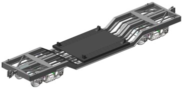
a)
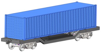
b)
Mathematical modelling was conducted for the dynamic load determination of the flat wagon carrying structure. The calculation considered shunting impacts and the research was made in the plane coordinates. It was taken into account that an impact load of 3.5 MN affected the rear stop of the automatic coupler. The study used the mathematical model given in [9]. This model considered displacements of a long-base flat wagon loaded with three tank containers. Therefore, the model was improved. Particularly, the model considered displacements of the carrying structure of the flat wagon without displacements of the freight transported. Thus, the freight transported was taken as a captive mass which completely repeated the trajectory of the carrying structure of the flat wagon. Besides, the model did not consider displacements of the carrying structure of the flat wagon as the basic model was shorter unlike the model considered in [9]. The mathematic model has the form:
where – mass of the carrying structure of a flat wagon; – inertia moment of the carrying structure of a flat wagon relative to the longitudinal axle; – value of the longitudinal impact to the automatic coupler; – bogie mass; – inertia moment of a wheelset; – radius of a mean worn-out wheel; – number of bogie axles; – half-base of a flat wagon; – absolute value of the dry friction force in a spring group; , – rigidities of the springs in the bogie suspension; , , – coordinates corresponding to the longitudinal, angular around longitudinal, and vertical displacements of a flat wagon, respectively.
System of equations Eq. (1-3) were solved in MathCad software using standard algorithms [10-15]. The initial displacements and speeds were taken equal to zero. The input parameters of the mathematical model were the technical characteristics of the flat wagon, parameters of a spring suspension and values of a longitudinal impact into the automatic coupler. It was considered that the flat wagon was loaded with conditional freight under the complete wagon load consignment. Fig. 2 shows that the maximum acceleration value on the carrying structure of the flat wagon was about 40 m/s2 (0.4 g). The acceleration value obtained did not exceed the normative value established in [16, 17].
The strength of the carrying structure of a flat wagon was studied with a spatial model in SolidWorks software [18]. The strength calculation was made by the finite element method [19-21]. The finite element model of the carrying structure of the flat wagon is given in Fig. 3.
Fig. 2The accelerations on the carrying structure of a flat wagon at shunting impacts
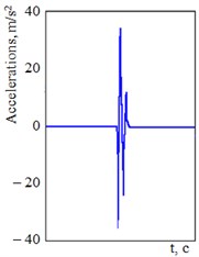
Fig. 3The finite element model of the carrying structure of a flat wagon

The model used isoparametric tetrahedrons. The model consisted of 225669 nodes and 679072 elements. The maximum size of an element was 105 mm, the minimum one 21 mm. The element size expansion ratio was 1.6. The minimum number of the elements in a circle was 8. The model was fixed in the supporting areas on the bogies. The structural material was the steel 09G2S.
Two loading diagrams for the carrying structure of the flat wagon were considered:
– transportation of military equipment, see Fig. 4(a) and
– transportation of a heavy container, see Fig. 4(b).
The design diagram considered the carrying structure elements which were in rigid interaction by welding or riveting. Thus, a rotating sector was neglected. It was considered that the carrying structure of the flat wagon was under the vertical load , and the longitudinal load on the rear stop of the automatic coupler .
Fig. 4The design diagram of the carrying structure of the flat wagon a) transportation of military equipment, b) transportation of a heavy container
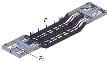
a)
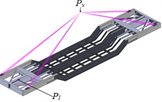
b)
The design diagram of the carrying structure of the flat wagon considered the vertical static load, distributed as a distance load, and the location of the container centre of gravity under the loading of a heavy container. On the basis of the calculation the authors defined the basic strength parameters of the carrying structure of a flat wagon. The results of the calculation are given in Figs. 5-6.
Fig. 5The stress state of the carrying structure of a flat wagon under transportation of military equipment
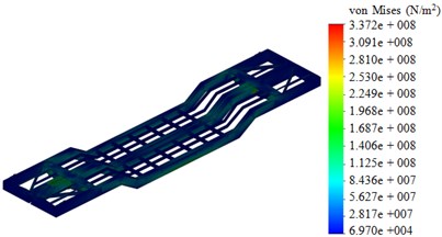
Fig. 6The stress state of the carrying structure of a flat wagon under transportation of a container
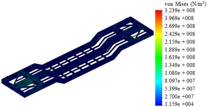
In the first design diagram the maximum equivalent stress was 337 MPа, displacement in structural units was 4.8mm, and strain was 4.35×10⁻³. The second design diagram demonstrates the maximum equivalent stress 324 МPа, displacement of 4.4 mm, and strain of 1.13×10⁻³. Thus, the maximum equivalent stresses were within the admissible values [16, 17, 22].
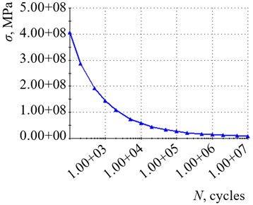
Further the strength capacity of the carrying structure of a flat wagon was ensured. The study also concerns with the fatigue strength calculation of the flat wagon structure. The test base included 107cycles. The fatigue curve was obtained by dividing each stress value of the curve SN by the elasticity modulus of the reference material (ASME) and multiplying the obtained value by the elasticity modulus of the considered material [18] (see Fig. 7). This curve was obtained in the CosmosWorks software environment for steel grade 09G2S. It characterizes the change in stresses of the material of the supporting structure of the platform wagon depending on the number of loading cycles.
The calculation of fatigue is implemented in a linear form when stress accumulation is diagnosed. The theory of damage accumulation suggests that a stress cycle with an alternating stress above the fatigue limit causes damage. Total damage is equal to the sum of the damage caused by individual stress cycles. That is, after applying loads to the calculation model with a loading cycle of 107, no damage was detected. The calculations made it possible to conclude that the fatigue strength of the carrying structure of a flat wagon was provided in operational load modes.
Fig. 7The fatigue curve of the carrying structure of a flat wagon
3. Conclusions
The carrying structure of a flat wagon of lower centre of gravity was designed. A 13-401 flat wagon was chosen as the prototype wagon. In order to transport military equipment, the middle part of the frame was lowered in comparison with that of the prototype (Fig. 1). Military equipment was placed on the rotating sectors made of composite material. Fitting outriggers were installed in the extension parts of the carrying structure of a flat wagon for transportation of heavy containers. The dynamic loading of the carrying structure of a flat wagon of lower centre of gravity was determined. The research was made in the plane coordinates. It was taken that the rear stop of the automatic coupler was under an impact load of 3.5 МN and the maximum acceleration on the carrying structure was about 0.4 g, thus it was within the admissible values.
The basic strength characteristics of the carrying structure of a flat wagon of lower centre of gravity were defined. The calculation was made with the finite element method. The study considered the loading on the carrying structure of a flat wagon under transportation of military equipment and a heavy container. It was established that the first design diagram had the maximum equivalent stress equal to 337 МPа, maximum displacements in the structural units were 4.8 mm, and strain of 4.35×10⁻³. The second design diagram had the maximum equivalent stress equal to 324×МPа, displacement of 4.4 mm, and strain of 1.13×10⁻³.
The fatigue calculations for the carrying structure of the flat wagon made it possible to conclude that the fatigue strength was ensured at operational loading modes. The research may encourage engineers to design unified carrying structures of flat wagons, and improve the rail transport efficiency.
References
-
WBN Waggonbau Niesky GmbH: Developing a Flexible Platform of Freight Wagons. International Edition, No. 1, 2016, p. 46.
-
Nader M., Sala M., Korzeb J., Kostrzewski A. A rail transport wagon as a new, innovative construction solution for the transport of semi-trailers and road sets for intermodal transport. Logistyka, Vol. 4, 2014, p. 2272-2279, (in Polish).
-
Rudakova E. O., Orlova A. M. The study of the dynamic properties of the articulated flat-car on mathematical modelsNauka ta progres transportu. Visnik Dnipropetrovskogo Natsionalnogo Universitetu Zaliznichnogo Transportu, Vol. 23, 2008, p. 85-88, (in Russian).
-
Chlus K., Krason W. Numerical standard tests of railway carriage platform. Journal of KONES Powertrain and Transport, Vol. 19, Issue 3, 2012, p. 59-64.
-
Sapronova S., Tkachenko V., Fomin O., Hatchenko V., Maliuk S. Research on the safety factor against derailment of railway vehicles. Eastern-European Journal of Enterprise Technologies, Vol. 6, Issue 7(90), 2017, p. 19-25.
-
Wickens A. H. The dynamics of railway vehicle – from stephenson to carter. Proceedings of the Institution of Mechanical Engineers, Vol. 212, 1999, p. 209-217.
-
Fomin O., Lovska A., Kulbovskyi I., Holub H., Kozarchuk I., Kharuta V. Determining the dynamic loading on a semi-wagon when fixing it with a viscous coupling to a ferry deck. Eastern-European Journal of Enterprise Technologies, Vol. 2, Issues 7(98), 2019, p. 6-12.
-
Fomin O., Gerlici J., Lovska A., Kravchenko K., Prokopenko P., Fomina A., Hauser V. Durability Determination of the Bearing Structure of an Open Freight Wagon Body Made of Round Pipes during its Transportation on the Railway Ferry. Communications-Scientific letters of the University of Zilina, No. 1, 2019, p. 28-34.
-
Bogomaz G. I., et al. The Loading of Tank-Containers, Located on the Railway Platform, When Struck in the Coupling. Dynamics and Motion Control of Mechanical Systems, Kyiv, ANU, Institute of Technical Mechanics, 1992, p. 87-95, (in Russian).
-
Kondratiev A. V., Prontsevych O. O. Stabilization of physical-mechanical characteristics of honeycomb filler based on the adjustment of technological techniques for its fabrication. Eastern-European Journal of Enterprise Technologies, Vol. 5, Issues 1(95), 2018, p. 71-77.
-
Kapitsa M., Mikhailov E., Kliuiev S., Semenov S., Kovtanets M. Study of rail vehicles movement characteristics improvement in curves using fuzzy logic mechatronic systems. MATEC Web of Conferences, Vol. 294, 2019.
-
Plakhtii O. A., Nerubatskyi V. P., Hordiienko D. A., Kavun V.Ye. Active single-phase four-quadrant rectifier with improved hysteresis modulation algorithm. Scientific Bulletin of National Mining University, Vol. 3, 2019, p. 103-108.
-
Kučera P., Píštěk V. Truck vibrations caused by rotating shaft deflection. Journal of Vibroengineering, Vol. 19, Issue 7, 2017, p. 5361-5373.
-
Píštěk V., Klimeš L., Mauder T., Kučera P. Optimal design of structure in rheological models: an automotive application to dampers with high viscosity silicone fluids. Journal of Vibroengineering, Vol. 19, Issue 6, 2017, p. 4459-4470.
-
Zajac, R., Prokop, A., Řehák, K. Determination of the modal parameters on the thin flat structures. Vibroengineering Procedia, Vol. 18, 2018, p. 91-95.
-
Freight Wagons. General Requirements for the Calculations and Design of New and Upgraded 1520 mm (non-self-propelled) railcars. DSTU 7598: 2014, 2014, (in Ukrainian).
-
Freight Wagons. Strength and Dynamic Quality Requirements. GOST 33211-2014, 2014, (in Russian).
-
Kurowski P. Engineering Analysis with Solidworks Simulation 2019. England, SDC Publications, 2019, p. 606.
-
Okorokov A. M., Fomin O. V., Lovska A. O., Vernigora R. V., Zhuravel I. L., Fomin V. V. Research into a possibility to prolong the time of operation of universal semi-wagon bodies that have exhausted their standard resource. Eastern-European Journal of Enterprise Technologies, Vol. 3, Issues 7-93, 2018, p. 20-26.
-
Lovskaya A., Rybin А. The study of dynamic load on a wagon-platform at a shunting collision. Eastern-European Journal of Enterprise Technologies, Vol. 3, 2016, p. 4-8.
-
Vatulia G., Falendysh A., Orel Y., Pavliuchenkov M. Structural improvements in a tank wagon with modern software packages. Procedia Engineering, Vol. 187, 2017, p. 301-307.
-
Railway applications - structural requirements of railway vehicle bodies, Part 2. Freight wagons. EN 12663-2, 2010.
About this article

The present study was conducted within the framework of the scientific topic of young scientists “Innovative Principles of Creation of Resource-Saving Structures of Railroad Cars by Taking into Account the Refined Dynamic Loads and Functional-Adaptive Flash Concepts”, which is funded by the state budget of Ukraine in 2020 and the authors gratefully acknowledge funding from the Specific research on BUT FSI-S-20-6267.
