Abstract
Desired optimum handling performance of the vehicle hardly be achieved at high vehicle speed due to unpredictable road condition such as uneven surface and slippery road during raining with the existing control algorithm. This paper is focusing on the integration of two robust controller which are Sliding Mode Controller (SMC) and Feedforward controller into the vehicle simulation model to improve the handling performance of the vehicle. Disturbance rejection problem arises from the SMC controller was highlighted and the solution proposed to overcome it. Through the simulation in Simulink, SMC-Feedforward shows average improvement of approximately 30.42 % and 39.41 % for J-Turn and Double Lane Change (DLC) test respectively. The proposed controller has successfully solved the disturbance rejection problem by minimizing the disturbance effect on the vehicle model, which improve the handling performance of the vehicle in terms of yaw rate and sideslip angle.
Highlights
- Implementation of Feedforward Sliding Mode Controller into the vehicle will improve the handling performance by minimizing the effects of unpredictable road condition.
- Vehicle model tracks the desired yaw rate while minimizing the side-slip angle during various maneuver condition.
- In extreme condition, Feedforward Sliding Mode Controller will send signal to ABS of the vehicle so that difference in braking torques in each wheel will provide corrective yaw rate required.
- Disturbance rejection problem arises from the SMC controller was highlighted and the solution is proposed.
- SMC-Feedforward controller managed to track the desired yaw rate with percentage difference error of less than 6 % compared to reference model.
- Some recommendation for future work such as the direct yaw moment control can be integrated with active steering control to provide better handling performance.
1. Introduction
Numerous researches have been done to improve the handling of the vehicle in term of yaw rate using active steering control such as Composite Non-linear controller, H∞ controller and fuzzy feed-forward controller. The main limitation of the active front steering controller is that it is able to work effectively in linear handling region. Many researches have been done on Direct Yaw Control (DYC) to improve the performance of the yaw rate to track according to the desired yaw rate, however there exist one limitation on the controller that is the controller is only able to control the yaw rate of the vehicle and without taking into the consideration of the side-slip angle. There are few researches on DYC to control the yaw rate and side-slip angle at the same time, however the controller ends up with some limitation and imperfection [1-3]. Improving yaw rate of the vehicle without minimizing the side-slip angle will end up the controllability of the vehicle to be less effective to the steering angle input when the side-slip angle is sufficiently large.
The advantage of the feed forward controller is the ability to work effectively in uncertainty environment such as different road coefficient of surface [4]. Adaptive sliding mode controller is also used for yaw stabilizing purpose for motor driven electrical vehicle [5]. Nam et. al. [5] design the adaptive sliding mode controller to maintain the stability of the vehicle model when undergo wide range of driving condition. However due to the limitation of the chattering effect introduced by the SMC controller, the disturbance rejection performance of the SMC controller is limited. Thus, by combining the SMC controller with feed forward controller, the handling performance of the vehicle will improve in terms of yaw rate and sideslip angle in the presence of road coefficient disturbance.
The objective of this paper is to design direct yaw moment controller to improve the performance of the 8 DOF vehicle model so it tracks the desired yaw rate while minimizing the side-slip angle during various maneuver condition.
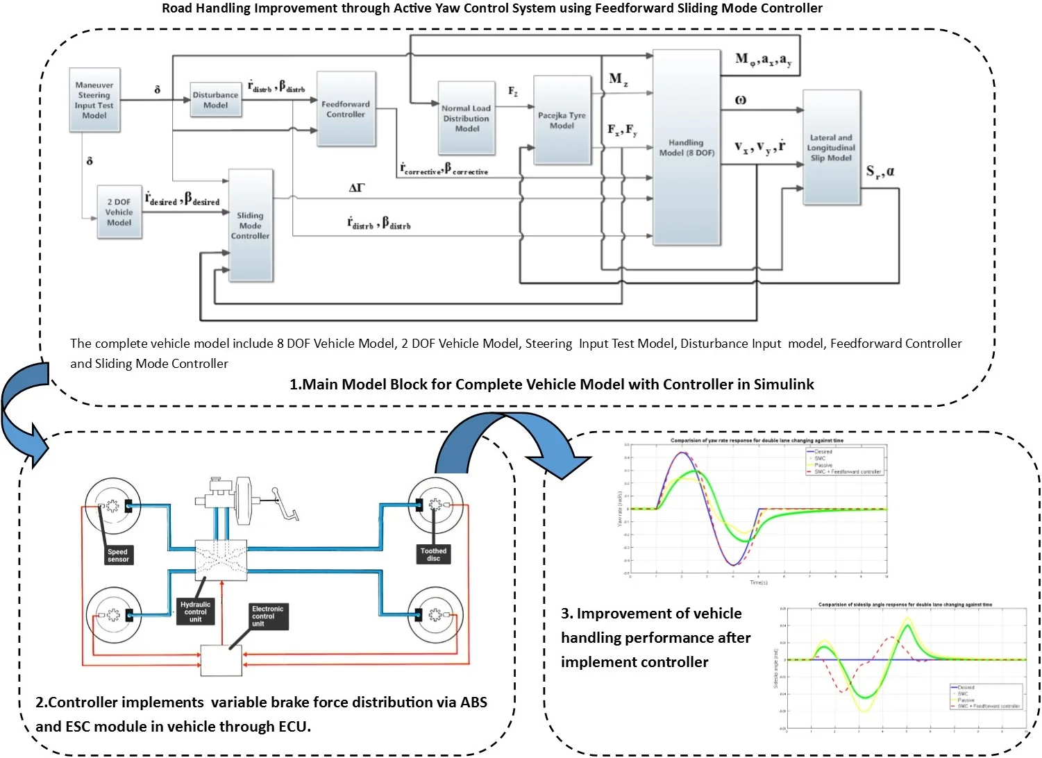
2. Controller design
This study will be start with the development of 2 DOF and 8 DOF vehicle dynamic model in Simulink software. 2 DOF vehicle model will acts as the reference model while the 8 DOF will be used to represent the actual vehicle handling response. Direct yaw moment control is used as the active chassis control because it works effectively in linear and non-linear handling region [6], and more stable even in the non-linear region of large slide-slip angle [7] and margin of longitudinal force to increase is very large to cope for critical handling condition [8]. The two control objectives for the controller to be designed are the yaw rate, and side-slip angle. The designed controller is implemented in the vehicle model to tune the yaw rate, as close as possible to the reference yaw rate and minimize the side-slip angle, to zero to improve the handling performance of the vehicle. The SMC-Feedforward controller will then be designed based on the vehicle model equation to achieve the control objectives.
2.1. Sliding model controller
The sliding surface to control the yaw rate and sideslip angle can be defined as:
where – actual yaw rate of the vehicle; – desired yaw rate of the vehicle; – actual sideslip angle of the vehicle; – desired sideslip angle of the vehicle; – positive design parameter.
The value of the positive parameter is used to represent the emphasis between the sideslip angle error and yaw rate error, since the unit of the yaw rate error and sideslip angle error is not equivalent hence the positive design parameter cannot represent the emphasis between the two error. In order to solve the limitation, the errors in the sliding surface in Eq. (1) is normalized and absolute [9]. The final form of the sliding surface is represented in Eq. (2):
Since the desired sideslip angle is equal to zero , Eq. (2) is further simplified into:
Differentiate Eq. (3) we get:
Stage 2: Develop feedback control law.
In order to drive the system trajectories to the sliding surface 0, the following condition must be satisfy [9]:
when the states of the vehicle are outside the sliding surface 0, Eq. (5) become:
In order to satisfy the condition in Eq. (6) and drive the state to sliding surface 0 the following control input is proposed:
From the yaw motion equation, rearrange the equation in terms of we get:
According to the control law, the derivative of the sliding surface must be equating to zero, in order for the control input to drive the desired states to zero. Setting Eq. (4) to zero we get:
Substitute Eq. (8) into Eq. (9):
Substituting Eq. (10) into Eq. (7):
The corrective moment in Eq. (11) is in the discontinuous form which in real practice will lead to a phenomenon known as chattering. Chattering will affect the performance of the controller at the same time causing the mechanical components of the vehicle to wear and tear faster. In order to solve chattering effect, the discontinuous term signum function in the corrective moment is replace with saturation function with boundary layer, [10]. The corrective moment equation become; let :
The torque command that is generated by the sliding mode controller to improve handling performance of the vehicle during critical manoeuvre [10] is:
where – torque command to be generated by each wheel, Nm; – corrective moment to be applied on the vehicle, Nm; – effective radius of the wheel, m; – track width, m, – front axle; rear axle.
2.2. Design of feedforward control
The controller will take the disturbance signal as input and generate corrective yaw rate and sideslip angle to the system to counteract the disturbance signal that is initially received from the system [11]. The general form of feedforward controller from Eq. (13) that will be input into Simulink model is:
where, – disturbance model; – estimated plant model for feedforward controller; – disturbance signal from disturbance model.
3. Results and discussion
The controller built for simulation is tested using DLC and J-Turn tests at 80 km/h as suggested in [12]. Figs. 1-4 shows the obtained results.
Fig. 1Comparison of yaw rate response for DLC against time
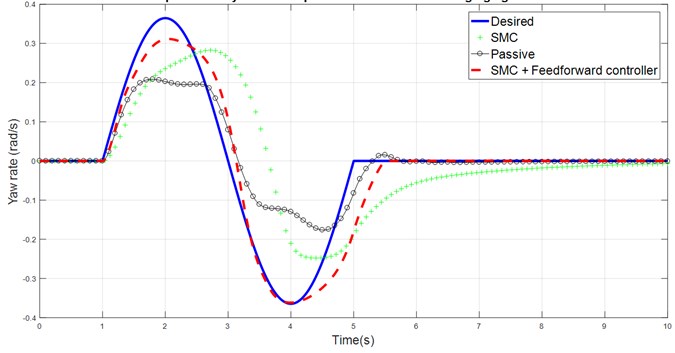
Fig. 1 shows that the yaw rate response of the vehicle is closer to the desired yaw rate performance after adding SMC, however the driver still required more effort to bring the vehicle back to neutral steer condition by turning the steering angle more and slow down the vehicle speed due to the presence of disturbance which limit the performance of vehicle equipped SMC controller. It can be seen that the response of the vehicle handling model equipped with SMC and feedforward controller label is able to track the desired yaw rate closely with some minor time lag after second peak value. The large sideslip angle in the uncontrolled vehicle response is the major cause of lower yaw rate and understeer response of the vehicle which is shown in Fig. 2 and 4. Due to the limitation of road tire lateral grip force, the yaw rate of the vehicle cannot further increase and eventually the vehicle response in the understeer behavior. The slow convergence and large changing of sign in the sideslip angle will affect the driver’s sense of control. Again, combination of feedforward controller with SMC controller is able to solve this problem, as shown in the results.
Fig. 2Comparison of sideslip angle response for DLC against time
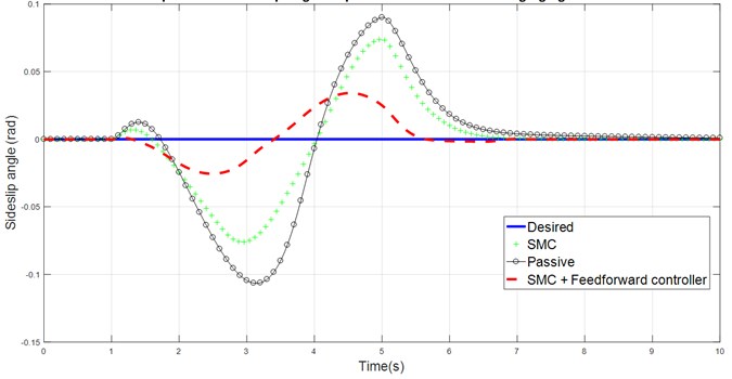
Fig. 3Comparison of yaw rate response for J-Turn against time
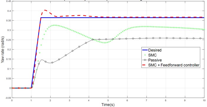
Fig. 4Comparison of sideslip angle response for J-Turn against time
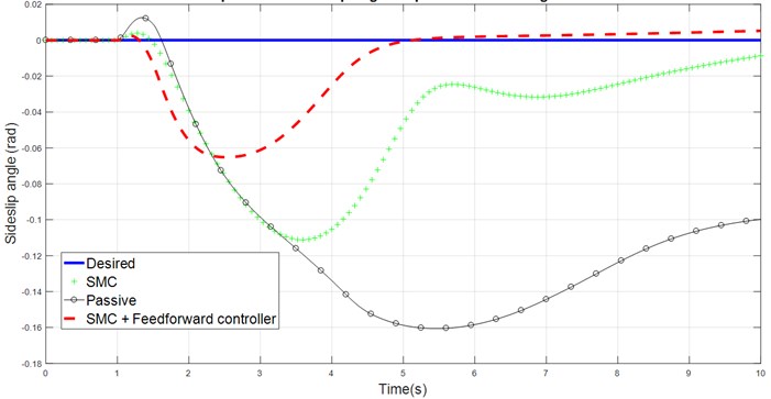
Table 1Overall results against original vehicle response without controller
Vehicle speed | 80 km/h | Road friction coefficient | 0.9 | |||
Test | J-Turn | |||||
Desired | Passive | SMC | Improvement | SMC-Feedforward | Improvement | |
Yaw rate | 0.358 rad/s | 0.23 rad/s | 0.29 rad/s | 16.67 % | 0.364 rad/s | 34.12 % |
Sideslip angle | 0 | 0.121 rad | 0.0553 rad | 54.46 % | 0.0282 rad | 76.76 % |
Test | DLC | |||||
Desired | Passive | SMC | Improvement | SMC-Feedforward | Improvement | |
Yaw rate | 0.258 rad/s | 0.152 rad/s | 0.21 rad/s | 22.46 % | 0.266 rad/s | 37.74 % |
Sideslip angle | 0 | 0.0471 rad | 0.0341 rad | 27.65 % | 0.0141 rad | 58.38 % |
4. Conclusions
Simulation results shows clearly that, passive system shows understeer condition with large vehicle sideslip angle for both maneuver test at high vehicle travelling speed of 80 km/h. Two controllers have been proposed and the performance of the controller has been compared and analyzed. SMC controller was designed with the aim of improving the yaw rate performance and minimizing the sideslip angle of the vehicle. Despite of improvement in both response after implementing, the vehicle is still in understeer condition due to the presence of disturbance which limit the capability of SMC controller. In order to minimize the effect of the disturbance, feedforward controller is added to the SMC, creating SMC-feedforward controller. The simulation results show that implementation of SMC-Feedforward controller performed better. SMC-Feedforward manage to track the desired yaw rate with RMS percentage difference error of less than 6 % at the same time reducing the sideslip angle of the vehicle. Therefore, it can be concluded that the objective is achieved where newly designed SMC-Feedforward controller improves the yaw performance while minimizing the sideslip angle of the vehicle response.
References
-
Tchamna R., Youn I. Yaw rate and side-slip control considering vehicle longitudinal dynamics. International Journal of Automotive Technology, Vol. 14, Issue 1, 2013, p. 53-60.
-
Zhao Y., Zhang Y., Zhao Y. Stability control system for four-in-wheel-motor drive electric vehicle. 6th International Conference on Fuzzy Systems and Knowledge Discovery, 2009, p. 171-175.
-
Zheng H., Zong C. Research on vehicle stability control algorithm for direct yaw moment control. International Conference on Computer and Electrical Engineering, Singapore, 2010, p. 55-62.
-
Hosseinian A. A. Integrated Control of Active Vehicle Chassis Control Systems. Ph.D. Thesis, Polytechnic University of Milan, 2018.
-
Nam K., Oh S., Fujimoto H., Hori Y. Design of adaptive sliding mode controller for robust yaw stabilization of in-wheel-motor-driven electric vehicles. International Journal of Vehicle Design, Vol. 67, Issue 1, 2015, p. 98-113.
-
Karbalaei R., Ghaffari A., Kazemi R., Tabatabaei S. A new intelligent strategy to integrated control of AFS/DYC based on fuzzy logic. International Journal of Mathematical, Physical and Engineering Sciences, Vol. 1, Issue 1, 2007, p. 47-52.
-
Abe M. Trends of intelligent vehicle dynamics controls and their future. NTN Technical Review, Vol. 81, 2013, p. 2-11.
-
Abe M. Vehicle Handling Dynamics: Theory and Application. 2nd Edition, Butterworth-Heinemann, Oxford, 2015.
-
Slotine J.-J.-E., Li W. Applied Nonlinear Control. Prentice Hall, New Jersey, 1991.
-
Fu C. Direct Yaw Moment Control for Electric Vehicles with Independent Motors. Ph.D. Thesis, Aerospace, Mechanical and Manufacturing Engineering, RMIT University, 2014.
-
Ogata K., Yang Y. Modern Control Engineering. Prentice Hall, New Jersey, 2002.
-
The Dynamic Test of Car Electronic Stability Control (ESC) Systems Protocol. Version 1.2, Euro NCAP, 2011.
About this article

