Abstract
In this paper a dual direct torque control (DDTC) strategy with second-order sliding mode control (SOSMC) controller of the doubly fed Induction motor (DFIM) is presented in order to overcome some drawback such as ripples in torque, flux and to improve dual direct torque control (DDTC) performance toward the electrical parameters variations. This control strategy used in the doubly fed induction machine supplied, coupled by two voltage source inverters in rotor and stator sides witches are linked to two switching tables in order to determined the rotor and stator flux vector control. This controller based on super-twisting algorithm (STA). Comparative results between a classical controller (PI) and the proposed controller can prove the very satisfactory performance and robustness of this new controller.
Highlights
- A new DDTC for DFIM have been presented.
- The transient responses and steady-state are insensitive to uncertainty parametric variation of the DFIM.
- Different methods of DDTC have been studied and realized.
1. Introduction
DFIM have characteristics to be the most promising motors, such as fast and robust response under transient conditions, high performance, excellent speed controllability, small converter size and relatively low cost compared to other machines, as confirmed by lot of papers [1-3]. The DFIM electrical behavior is described in mathematical equations showing how it behaves as three-phase stator and rotor circuits coupled to the voltage source inverter. DDTC strategy is applied [4-8] to achieve high performance torque control and reduce the complexity of the algorithms involved in the field-oriented control FOC [9, 10] by eliminating the coordinate transformation. However, the performances of classical DDTC are often characterized by high torque and flux ripples as variable switching frequency.
Several approaches are suggested on the development of DDTC techniques operating at a constant switching frequency using artificial neural network [11], where the goal is the reduction of the flux and torque ripples, but these controllers are not robust to uncertain parameters.
SOSMC algorithm has already been applied and attracted a lot of research for the last three decades now of its simplicity, external disturbances and robustness to parameter variations [13-15].
In this paper a new combined DDTC-SOSMC method using super-twisting algorithm is presented.
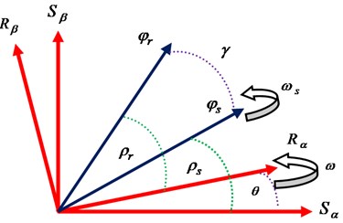
2. Mathematical model of DFIM
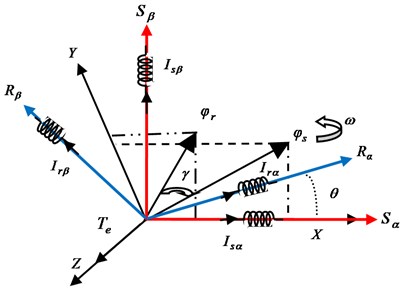
The voltages and flux equations of the DFIM are given as follows [1]:
Fig. 1Flux vector diagram of DFIM
The mutual inductance is given by [2]:
The DFIM torque can be expressed as:
We define disturbance terms , , , as follows [3]:
where:
That, we define stator and rotor transmittances terms as:
From Eq. (2), (4) and (5) the DFIM flux model can be represented as shown in Fig. 2.
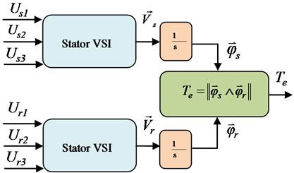
The stator and rotor flux are estimated respectively by:
During the switching interval we can write:
By neglecting the resistive effect, we can use:
Then:
As it can be noted that the coupling terms , , , are a low value and we can neglect this terms in relation to the nominal values of the voltages level, , , , .
Fig. 2Bloc diagram of DFIM flux model
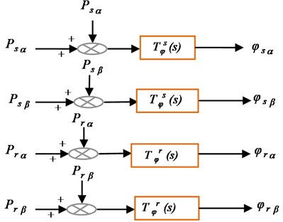
Fig. 3Block scheme of VSI and DFIM model
3. DDTC applied to the DFIM
3.1. Vectors flux control
During the period , we can write:
Fig. 4φs and φr deviation
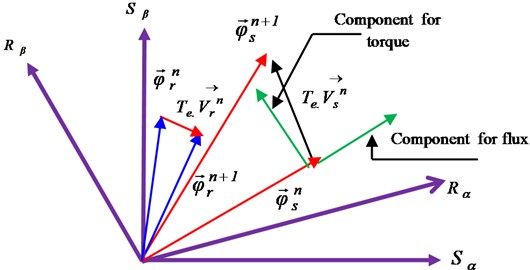
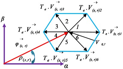
Fig. 5Vs and Vr in six angular sectors
From Eq. (10), we notice that the ends of and moves as shown in this Fig. 4.
Where, the eight stator and rotor voltages vectors are presented in Fig. 5.
3.2. Flux corrector
To control and and theirs angular positions (, ) we need to use four hysteresis comparators so as illustrated in Fig. 8.
Fig. 6Hysteresis controllers
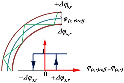
Fig. 7 shows the relation between and :
Fig. 7Stator and rotor flux loci
3.3. Elaboration of the switching table
To increase the magnitude of and , in sector 1 (Fig. 5), the voltage vectors , can be selected. Conversely, a decrease can be obtained by , . For the stator and rotor flux angular position , the voltage vectors , are used to increase it, and it decreased by , . All the possibilities are given by Table 1 [6].
Table 1Switching table
Torque | Flux evolution | Sector number | ||||||
1 | 2 | 3 | 4 | 5 | 6 | |||
Voltage vector | ||||||||
+ | + | + | V2 | V3 | V4 | V5 | V6 | V1 |
– | + | – | V6 | V1 | V2 | V3 | V4 | V5 |
+ | – | + | V3 | V4 | V5 | V6 | V1 | V2 |
– | – | – | V5 | V6 | V1 | V2 | V3 | V4 |
4. Design of SOSMC-DDTC of DFIM
The main advantage of the conventional sliding mode control (SMC) strategy is to modify the dynamics of a nonlinear system to a predefined sliding variety. This strategy presents invariant properties to model parameters uncertainties and modeled dynamics, as well as finite time convergence in the presence of bounded perturbations [14, 15]. The SOSMC is known for the ability to suppress chattering effect to improve the performance of control systems.
This section includes the STA to reduce flux and torque ripples, and keeping the advantage of robustness and convergence in finite time. In the SOSMC-DDTC, the sliding surfaces are selected to be suitable with the speed errors.
4.1. Super twisting algorithm (STA)
The ability of STA to suppress chattering without degrading the transient response resides in the capacity of this algorithm to set the dynamics in a small area of the discontinuity surface to evade real discontinuity without affecting the tracking accuracy and robustness. The STA, like other algorithms of the same categorical utilize a continuous nonlinear function with infinite gain [15], requires only the information on S and causes the cancellation of that one in a finite time; it also makes it possible to construct a differentiator called generally an exact differentiator. The control law is suggested by [15]:
where and are positive bounded constants.
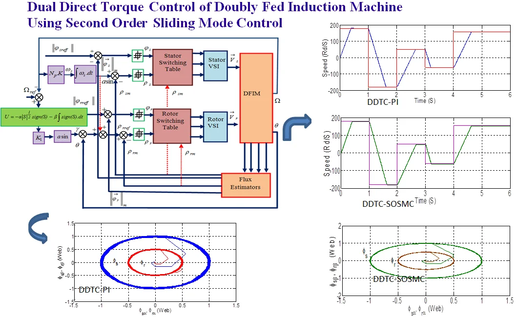
Fig. 8Bloc diagram of the SOSM-DDTC of the DFIM
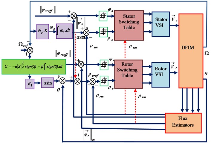
The proposed SOSMC-DDTC is shown in Fig. 8, where the SOSMC-DDTC consists in replacing the classical regulator PI by the SOSMC controller. In this bloc diagram, we used 4 hysteresis comparators, where the comparators inputs is the error between the desired ()values with estimated flux values calculated as shown in Eq. (7), and the difference between desired angular positions () with the measured values [4, 5]. The comparators outputs are connected to tow switching tables such as the stator and rotor inverter switching frequency changed according to the hysteresis bandwidth of comparators.
5. Simulation results
To confirm the effectiveness of the STA in SOSMC-DDTC of DFIM; a series of comparisons results between the proposed SOSMC –DDTC controller and the classical regulator PI presented in following figures.
5.1. Speed reversal
The first test concerns the speed evolution and the disturbance rejection of SOSMC and PI controller. This test is related to the performances of the drive system at high and low reference speed. The rotor reference speed was suddenly changed from 180 rd/s to –180 rd/s at 1 s, then it was increased and decreased towards 50 rd/s at 2 s and –50 rd/s at 3 s respectively, finally it was set to 157 rd/s at 4 s with the application of a step increase in load torque at 0.5 s without any change in parameters during the simulation time.
It can be seen that the actual DFIM speed follow the reference speed with no overshoot and good accuracy and rejects the load disturbance rapidly with a maximum drop of speed. Also, we can observe the reduction of chattering in the flux and torque ripple using SOSMC controller compared to PI controller.
Fig. 9Simulation results with a) PI controller, b) SOSMC controller
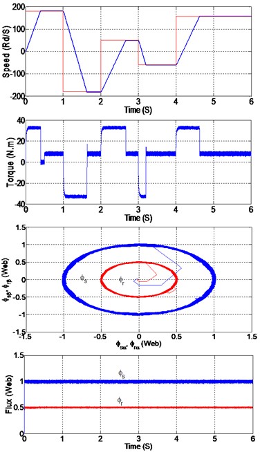
a)
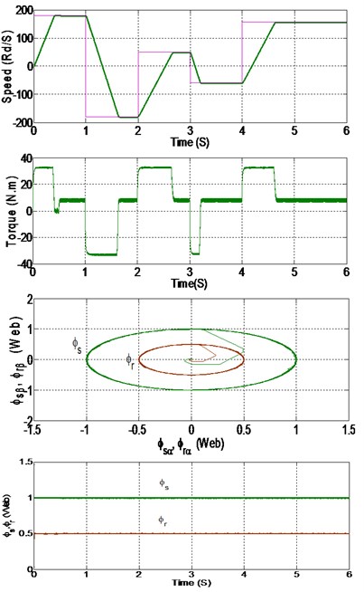
b)
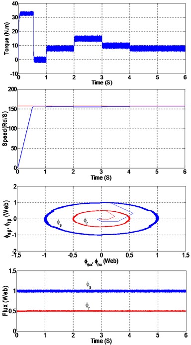
5.2. Variation of the load torques
The second test deal the system responses behavior realized with PI and SOSMC controllers, after the application of the changes in the load torque as illustrated in Fig. 10.
We notice that the SOSMC reacts faster than the classical PI when load torque is suddenly applied and removed. The speed responses are not affected by the load torque variations and reject the load disturbance very rapidly with no overshoot, with a negligible steady state error, flux and torque ripple has also a notable reduction in SOSMC compared to classic PI.
Fig. 10Simulation results with a) PI controller, b) SOSMC controller
a)
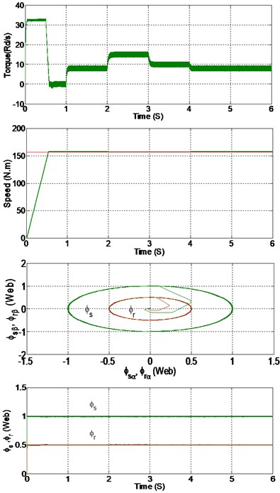
b)
5.3. Variation in the stator and rotor resistances
In the third test we have studied the effect of the parameters uncertainties on the performances of SOSMC and we compared with the PI control. To show this effect, we have simulated the system with different values of and resistancesand compared to nominal value.
5.3.1. Variation in the stator resistance
Fig. 11Variation in the stator resistance
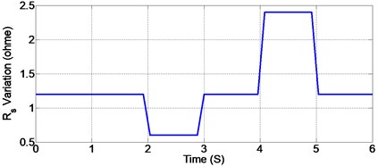
Fig. 12Simulation results with a) PI controller, b) SOSMC controller
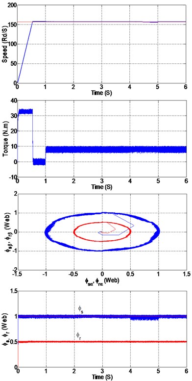
a)
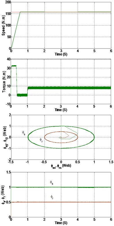
b)
5.3.2. Variation in the rotor resistance
It is obviously that the impact of the electrical parameters change on the drive performance is more important when we use the classic PI controller. We observe that the start-up speed, dynamics performance, the torque and flux chattering during the variation of parameters has also a notable reduction. The new approach offers significant improvements compared with PI.
Fig. 13Variation in the rotor resistance
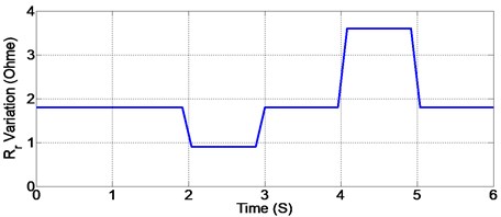
Fig. 14Simulation results with a) PI controller, b) SOSMC controller
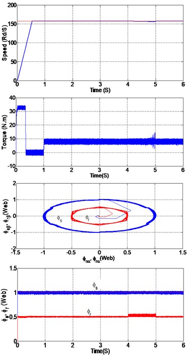
a)
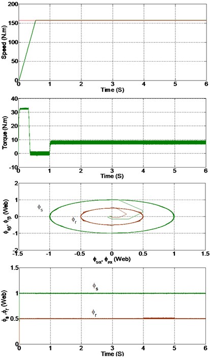
b)
Table 2 presents the quantitative analysis of the two approaches. The comparison implicates that the proposed SOSMC gives less chattering with a seamless transient response.
Table 2Performances comparison of the two controllers
Approach | PI | SOSMC |
Robustness to parameters variation | High | Low |
Chattering | Medium chattering | Low chattering |
Transient performance of the speed | Relatively fast with medium settling time | Low settling time |
Rising time of the speed | 0.16 s | 0.12 s |
Implementation Complexity | High | Low |
Table 3DFIM parameters
1.2 Ω | |
1.8 Ω | |
0.1554 H | |
0.15 H | |
2 | |
0.07 Kg.m2 |
6. Conclusions
A new SOSMC-DDTC algorithm for DFIM is presented. The simulation results show the robustness and good performance of the proposed controller in different operational conditions such as variation of the load torque, reference speed, and stator and rotor resistances. This new controller has the advantage in handling the torque and flux ripple, good responses at high and low speed and rejects the load disturbance very rapidly, and the robust to parameter variation. The simulation results confirm that the fast and good response of the proposed controller system is much better than classical PI.
References
-
Han P., Cheng M., Chen Z. Single-electrical-port control of cascaded doubly-fed induction machine for EV/HEV applications. IEEE Transactions on Power Electronics, Vol. 32, Issue 9, 2017, p. 7233-7243.
-
Zemmit A., Messalti S. Modeling and simulation of doubly fed induction motor (DFIM) control using DTC and DFOC: a comparative study. International Journal of Applied Engineering Research, Vol. 8, Issue 11, 2016, p. 5623-5628.
-
Choug N., Benaggoune S., Belkacem S. Hybrid fuzzy reference signal tracking control of a doubly fed induction generator. International Journal of Engineering (IJE), IJE Transactions A: Basics, Vol. 33, Issue 4, 2020, p. 567-574.
-
Bonnet F., Vidal P. E., Pietrzak-David M. Dual direct torque control of doubly fed induction machine. IEEE Transactions on Industrial Electronics, Vol. 54, Issue 5, 2007, p. 2484-2490.
-
Boumaraf F., Bendaas M. L., Abdessemed R., Belkacem S. Direct torque control of doubly fed induction machine. International Journal on Electrical Engineering and Informatics, Vol. 7, Issue 3, 2015, p. 541-555.
-
Boumaraf F., Khettache L., Belkacem S., Abdessemed R., Bendaas M. L. Torque ripple minimization of dual direct torque control of doubly fed induction machine using fuzzy logic. Journal of Electrical Engineering, Vol. 13, Issue 4, 2013, p. 216-223.
-
Abdellatif M., Debbou M., Belkhodja I. S., David M. P. Simple low-speed sensorless dual DTC for double fed induction machine drive. IEEE Transactions on Industrial Electronics, Vol. 61, Issue 8, 2014, p. 3915-3922.
-
Zemmit A., Messalti S., Harragab A. A new improved DTC of doubly fed induction machine using GA-based PI controller. Ain Shams Engineering Journal, Vol. 9, Issue 4, 2018, p. 1877-1885.
-
Drid S., Tadjine M., Naît Saîd M.-S. Robust backstepping vector control for the doubly fed induction motor. IET Control Theory and Applications, Vol. 1, Issue 4, 2007, p. 861-868.
-
Mohammed T., Mezouar A., Terras T., Hadjeri S. Variable gain PI controller design for speed control of a doubly fed induction motor using state-space nonlinear approach. Engineering, Technology and Applied Science Research, Vol. 3, Issue 3, 2013, p. 433-439.
-
Khadar S., Kouzou A. Dual direct torque control of doubly fed induction machine using artificial neural network. International Conference on Pattern Analysis and Intelligent Systems, Algeria, 2018.
-
Yaichi I., Semmah A., Wira P., Djeriri Y. Super-twisting sliding mode control of a doubly-fed induction generator based on the SVM strategy. Periodica Polytechnica Electrical Engineering and Computer Science, Vol. 63, Issue 3, 2019, p. 178-190.
-
Ouada L., Benaggoune S., Belkacem S. Neuro-fuzzy sliding mode controller based on a brushless doubly fed induction generator. International Journal of Engineering, Transaction B: Applications, Vol. 33, Issue 2, 2020, p. 248-256.
-
Levant A., Alelishvili L. Integral high-order sliding modes. IEEE Transactions on Automatic Control, Vol. 52, 2007, p. 1278-1282.
-
Levant A. Higher-order sliding modes, differentiation and output feedback control. International Journal of Control, Vol. 76, 2003, p. 924-941.
Cited by
About this article

