Abstract
The mode of a two-mass cone crusher at the approaches to one of the Sommerfeld thresholds is considered. Frequency close to this threshold from low side provides the most efficient energy transfer from the unbalance to the crusher body. However, the stochastic model of crushing shows the possibility of breakdown such mode even after a very long stay on it. The process can be stabilized by introducing a simple control into the system with an input signal from the unbalance tachometer.
1. Introduction
Improvement of vibration technology went in the direction of increasing three main indicators of the quality of its work: stability, gain, balance. Single-mass construct, although it was simple and cheap, did not give good quality for any of the three types mentioned. Poor stability means a quick departure from the initial parameters of the vibrating machine. The low gain forced to overestimate the force of the vibrator. If it was made in the form of an unbalance or crank mechanism, an increase in the load on it accelerated the destruction. Poor balance led to the same negativity, besides the harm that increased leakage of vibration into the environment. Already two-mass circuits gave a good gain and balance. Three-mass ones added stability, however, the increased complexity of manufacturing in this case a vibration machine left room for improving two-mass circuits.
In particular, the current model of a two-mass dynamic system, made in the form of a vibration cone crusher [1-3] with 9 degrees of freedom, with two independent unbalance vibrators (two degrees of freedom) driven by asynchronous engines, proved to be very promising. Five degrees of freedom out of a possible twelve in it were removed by the connection between the body and the striker, made in the form of a cone, leaving them the possibility of only reciprocating motion relative to each other. The mortar and the hopper were made in the body. The restriction of the degrees of freedom of the striker relative to the mortar allowed in the work mode to get rid of such parasitic phenomena as independent with respect to the mortar at first, horizontal vibrations of the striker and, at second, torsional vibrations of the striker around one or another horizontal axis. Both those and other vibrations can cause completely unnecessary strikes of the striker against the mortar. This construct, however, left some problems open. The wonderful process of self-synchronization of a pair of unbalances is very difficult for an accurate description, not to mention an analytical study even at idle. Therefore, in common approaches to the analysis of the working stroke, synchronization is accepted as held. What are the forces that stabilize self-synchronization, and, more importantly, how they affect work efficiency, the Sommerfeld thresholds, remain outside the scope of the study. Here we will try to answer the question about the behavior of the crusher under the assumption that the forces of stabilization of synchronization are negligible. To do this, introduce a construct with an even greater restriction on the number of degrees of freedom (see Fig. 1). Namely, supply the mortar with guides parallel to the guides connecting it to the striker. The unbalances are combined in a two-shaft vibrator, i.e. “mechanical synchronization” is made. Describing such a model by differential equations, a two-shaft vibrator is equivalent to a single-shaft one, because the lateral forces in both cases do not participate in the dynamics. In Fig. 1, for simplicity, a single-shaft vibrator is shown.
Fig. 1Diagram of a two-mass vibration crusher with three degrees of freedom
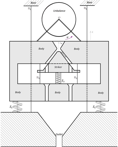
The geometrical axis of the vibrator shaft, denoted by , is perpendicular to the plane of Fig. 1. The unbalanced vibrator is driven by an asynchronous engine. The striker directly producing crushing is mounted on springs attached to the lower part of the body. A conical recess is made in the body, which corresponds to the striker. Thus, the body is a movable mortar. On the lower edge of the working surface of the striker several holes are made for the exit of crushed ore. Under them, at the base, there are receiving holes.
The striker has one degree of freedom relative to the body, which corresponds to a rectilinear relative displacement from each other in a certain direction along the guides . In the absence of rotational motions of the body, this means that any interactions between the striker and the body can cause acceleration of the body only in the direction. In particular, if is a vertical, then the mentioned acceleration can only be vertical. That is, there will be no lateral loads on the guides . Ore falls into the upper part of the gap between the striker and the mortar. The body can only move vertically along the guides . That is, it can make rectilinear vertical vibrations along the guides .
2. Equations
The system of differential equations for the crusher at idling was reduced by the authors in [4]. Now, the function is added to it to simulate the crushing process:
where, is the mortar displacement, in mm; is the mortar velocity, in mm/sec; is the striker displacement, in mm; is the striker velocity, in mm/sec; is the the rotational angle of the unbalance mass center, counted from its lowest point counterclockwise, in rad; is the angular speed of unbalance rotation, in rad/sec; is the unbalance inertia moment; is the unbalance inertia moment relative to the rotational axis; is the distance between the unbalance mass center and the rotational axis; , , are the masses of the unbalance, the mortar and the striker, respectively; , are the stiffness coefficients of the elastic bonds of the mortar with the base and the striker with the mortar, respectively; is the engine power at current moment, in watts; is the magnetic field rotational speed of the engine; is the coefficient characterizing the nameplate torque of the asynchronous engine.
The physical parameters involved in the system Eq. (1) were taken close to the parameters of the mentioned above physical model with 9 degrees of freedom. Namely: kg, kg, kg, N/m, N/m. According to the unbalance geometry, its inertia moment was calculated as kg⋅m2. The parameter was taken equal to 0.01 Nmsec.
Numerical experiments were carried out in the Maple mathematics system. A fourth-order Runge-Kutta method with a constant step 5⋅10-4 was implemented as an integrator.
3. Crushing model
Crushing occurs when the crusher and the mortar get closer. Ore is crushed in the gap between the crusher and the mortar. The destruction time of a piece of ore is significantly less than the time of one oscillation of the striker and of the mortar, as well as the time of one unbalance revolution. And even it is less than the optimal integration step, which provides the minimum error of the numerical simulation of the system at idle. Therefore, it is advisable to search for function among delta functions.
The presence of delta function in the right part of the ordinary differential equation corresponds to an instant change in the function, the derivative of which stays in the left part. Transform the system Eq. (1) according to this remark. Let , where is some number. Then, replacing in system Eq. (1) by 0, replenish it with non-differential equations:
They act instead of corresponding 3 equations in Eq. (1) only at moment .
Proceed to the modeling of random variables: , which is the force of the impact of a piece of ore on the striker and the body, and , which is the time of this impact.
According to the construction, is non-negative. Assume that the act of crushing leaves a noticeable share of approach speed just before this act. In other words:
So, at random times , according to the system Eq. (2), speed jumps of the striker, the body and the unbalance occur. The magnitude of the jumps depends on the random parameter , which is non-negative and does not exceed the value of . So, setting , where is a random value distributed on [0, 1], does not violate the construction logic. Choose a uniform distribution for .
4. Results
Of interest is the connection of the experimentally discovered frequencies of Sommerfeld effect with analytically calculated frequencies of free oscillations of the crusher with a fixed unbalance, which are the modules of the roots of the biquadratic characteristic equation:
In numerical experiments, the construct was started from zero initial values of the variables at idle, and the working stroke was switched on from the first second. Further, the process was investigated only up to the 10th second, since practical stabilization was observed. During each experiment, the power frequency of the asynchronous engines was unchanged. At the beginning, the frequency range from 95 rad/sec to 300 rad/sec was viewed in increments of 5, and then, in places suspicious of the Sommerfeld effect (SE), refinement was performed in steps of 1. Two Sommerfeld thresholds (ST) were detected. The first is about 126 rad/sec, the second is about 188 rad/sec. On the second, SE was much brighter than on the first ST.
Table 1Crusher operation parameters near the Sommerfeld thresholds
max | min | max | max () | usage | max () | ||
120 | 107.10 | 94.17 | 26.03 | 19.066 | 0.545 | 8.8E-02 | 11.766 |
125 | 108.75 | 93.396 | 33.21 | 25.9411 | 0.6269 | 0.10688 | 13.3854 |
126 | 129.52 | 118.27 | 11.46 | 2.5769 | 0.0606 | 0.0074 | 4.75974 |
127 | 128.15 | 121.18 | 10.94 | 1.51382 | 0.0643 | 0.00815 | 3.88281 |
187 | 153.88 | 139.05 | 26.85 | 13.116 | 0.686 | 1.3E-01 | 13.966 |
188 | 153.8 | 139.29 | 27.03 | 13.5561 | 0.688 | 0.13267 | 13.3443 |
189 | 189.75 | 185.44 | 23.35 | 1.759 | 0.020 | 2.5E-03 | 3.244 |
190 | 188.21 | 139.35 | 28.02 | 13.582 | 0.534 | 7.0E-02 | 12.204 |
191 | 190.97 | 180.24 | 23.16 | 1.390 | 0.047 | 6.0E-03 | 2.877 |
is the full energy accumulated in the crusher, is the unbalance energy | |||||||
As we can see, the efficiency of engine usage (ratio of real power take-off to the maximum possible for the engine) at the second threshold is higher than at the first, as well as the ratio of the work () performed to the force on the unbalance shaft. Nevertheless, the parameters have the same order. When ST passed, these parameters decrease tenfold.
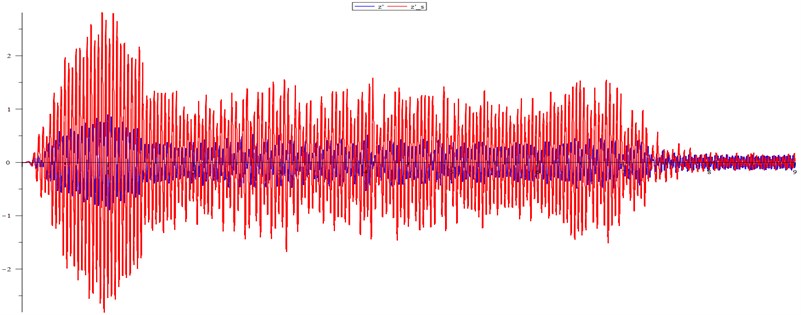
When simulating crushing by simple friction, the Sommerfeld threshold is a specific number. The random nature of the ore resistance turns the threshold into a band. So in the experiment at magnetic field frequency of 188 rad/sec (see Fig. 2) after the start of crushing in the first second for a long time (1.8-6.8 sec) in the process there were no changes, and we observe SE. The power take-off was about 0.6. After 6.8 sec, everything changed dramatically. The unbalance speed rose from 150 rad/sec to 175 rad/sec. Energy consumption, respectively, decreased by 5 times. The same phenomenon was discovered with shortening of duration of SE when the frequencies of the magnetic field (FMF) run from 186 rad/sec to 194 rad/sec. So, we have a resonance band () of FMF. It depends, of course, on nameplate engine power. In our linear model of the power the connection between the bands for different name plate engine power are close to linear. It can be found from torque equality: ,
Fig. 2Acceleration, adaptation to crushing, the Sommerfeld effect, destruction of the effect (ω= 188 rad/sec)
The following figure shows the dynamics of the device on a large scale as it was before, and during the transition.
Blue is the speed of the body, green is the acceleration of the body, “saw” is the angle of rotation of the unbalance mass center, measured from the lower position, purple is the vertical component of the acceleration of the unbalance mass center relative to its axis of rotation (since this axis moves with acceleration, the absolute acceleration of the unbalance mass center is different).
Fig. 3Destruction of the Sommerfeld effect in the interval 6.9-7 sec (ω= 188 rad/sec)
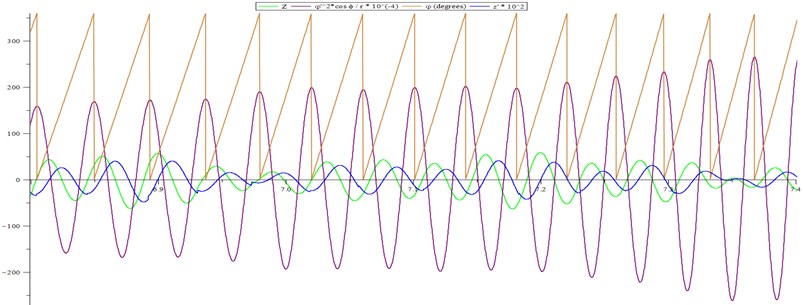
When violet and blue have different signs, the unbalance rotation energy passes into the kinetic energy of the body, when the signs are the same the energy flow is opposite.
The figure gives an understanding of the event, which led to a jump beyond the ST. Two large pieces of ore fell in a row and the body speed decreased significantly (6.9-7 sec). Therefore, despite the fact that the unbalance and the body speed turned out to be in antiphase (i.e., two turns the unbalance only gave energy to the body and received nothing back), the unbalance for two turns transferred a very small fraction of the rotational energy received from the engine into the body. Its remainder went to increase the angular velocity, and the unbalance phase shifted relative to the phase of the body. This led to a change in the balance in the transfer/return of energy from the unbalance to the body in favor of the return. The unbalance speed increased to an irreversible value.
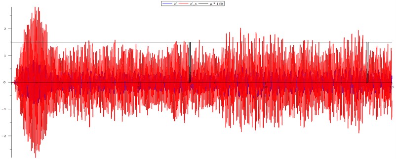
Simple control can keep the operating mode near the ST. So, in the presence of indications from the tachometer on the rotor, you can simply turn off the engine power for a while when the angular speed of a given level is reached, and there are other simple methods [5].
According to experimental data, some of which are given in Table 1, the amplitude of the oscillations of the angular velocity of the unbalance is about 5 % of its average value. Therefore, it seems sufficient to limit the angular velocity at the theoretically calculated second resonant frequency of 147.32 rad/sec to 155 rad/sec. The experiments confirmed this assumption (see Fig. 4). The graph of voltage supply to the engine is shown in black.
Fig. 4Power supply current control keeps the Sommerfeld effect (ω= 188 rad/sec)
5. Conclusions
The random nature of the crushing process leads to the appearance of a speed band of the magnetic field of an induction motor and, to its corresponding frequency band of the supply current, in which the Sommerfeld effect can exist for a long time which is a random value. Its expectation decreases as the frequency of the power supply current approaches the right end of the band. If there is feedback in the form of a signal from the tachometer, one can stabilize the mechanism on the mode by simply controlling the power supply voltage according to the signal.
References
-
Blekhman I. I., Blekhman L. I., Yaroshevich N. P. Upon drive dynamics of vibratory machines with inertia excitation. Journal Obogashchenie Rud, Vol. 4, 2017, p. 49-53.
-
Vaisberg L. A., Kazakov S. V., Shishkin E. V. Vibrational disintegration of solid materials in quasiresonant modes. Proceedings of the 29th IMPC, Pt. 2. Comminution and Classification, Vol. 81, 2018, p. 40-48.
-
Shishkin E. V., Kazakov S. V. Dynamics of vibratory crusher in resonance frequency range. Journal Obogashchenie Rud, Vol. 6, 2014, p. 29-33.
-
Morozov P. D., Miheev S. E. Mathematical model of the vibration cone crusher with three degrees of freedom. Vibroengineering Procedia, Vol. 25, 2019, p. 42-47.
-
Zubov I. V., Zubov A. V. The stability of motion of dynamic systems. Doklady Mathematics, Vol. 79, Issue 1, 2009, p. 112-113.
Cited by
About this article

Financial support was provided by the Russian Science Foundation No. 17-79-30056 (Project REC “Mekhanobr-tekhnika”).
