Abstract
The paper considers the main tasks of autonomous unmanned underwater vehicles (AUV), lists the requirements for the onboard computing environment. Comparative analysis of central processing unit (CPU), graphics processing unit (GPU), field-programmable gate array (FPGA) and application‐specific integrated circuit (ASIC) has been carried out. The FPGA was considered in more detail as the basis of the AUV onboard computing environment. The given example of designing a device that calculates an arithmetic function demonstrates the high performance of an FPGA and the complexity of developing a simple device in comparison with a similar task on a CPU.
1. Introduction
The oceans are a huge reservoir of hydrocarbons, mineral resources, and biological resources, which can represent a huge reserve for future generations. And the more we learn, the more questions related to the development of technology arise: how to touch these resources? How to get them from great depths? How to evaluate them? How not to damage these deep-sea ecosystems?
The safest and most effective way to explore the depths of the ocean is to use technical means that ensure the indirect presence of a person under water. Autonomous unmanned underwater vehicles play an important role in this. Autonomous robotic platforms arouse more interest in recent decade and broadly conducted in maritime approaches to achieve routine and permanent access to the underwater environment [1].
AUVs are unmanned, self-propelled vehicles that are typically deployed from a surface vessel, and can operate independently of that vessel for periods of a few hours to several days [2]. The time of continuous operation of the vehicle under water depends on the project, the type of its energy source. There are now more than 50 companies or institutions around the world operating AUVs for a variety of purposes. For example, the offshore gas and oil industry uses them for geologic hazards surveys and pipeline inspections, the military uses them for locating mines in harbors among other applications, and AUVs have been used to survey marine archeological sites and search for aircraft and ships lost at sea [3].
To solve these tasks, the AUV must meet the following requirements:
1) the motion control system should provide minimum yaw along the heading and pitch (especially when surveying with side‐scan sonar), as well as movement at a given distance from the ground or a given depth;
2) the navigation system should allow you to move along the route, go to a given object and determine the location of the object with an accuracy of several meters;
3) the technical vision system must ensure the recognition of specified objects (cable, oil pipeline) located at the bottom, and the determination of their orientation in the horizontal plane;
4) the behavior planning system should ensure the implementation of a given trajectory, as well as the necessary maneuvering when a given object is detected [4].
The above criteria for AUVs require a high‐performance onboard computing environment which has the following characteristics:
1) filtering and processing many signals from various sensors on board the underwater vehicle in а parallel way;
2) determining the coordinates and parameters of the movement of the AUV in real time, using the method of the strapdown inertial navigation system, which requires large computational costs;
3) planning a trajectory depending on the task and the situation using machine learning (artificial intelligence);
4) communication with other objects under water (AUV, ship, submarine).
The task of design such a high‐performance onboard computing environment can be solved by processor units, graphics accelerators, field‐programmable gate arrays and application‐specific integrated circuits which can operate in common or separately.
2. Comparative analysis of CPU, GPU, FPGA and ASIC
The intensive development and improvement of digital devices leads to their active use in various fields and technology, including in digital signal processing, data transmission, storage systems, as well as in special-purpose systems. Separately, it is worth noting control systems used in the aerospace/maritime industry, in military technology (for example, as digital ground/sea and onboard equipment), in the management of nuclear power plants, in medicine and other industries. Disruption of such critical control systems can cause significant economic or environmental damage, pose a threat to human health or life, and sometimes even lead to catastrophic consequences. Therefore, the design of reliable systems is one of the key problems of modern science and engineering practice. To create such reliable systems, it is necessary to analyze each modern hardware platform, to identify the advantages and disadvantages of each of them.
The CPU is one of the most flexible solutions — a universal processor can run any algorithm using many different programming languages. But this universality has its drawbacks, each useful operation of the algorithm includes a set of additional such as instructions, transferring data to the cache, transferring data between registers and other instructions. Each additional operation is a loss of computation speed and high‐power consumption.
GPUs today handle “computer graphics” very efficiently, thanks to a specialized pipelined architecture, they are much more efficient at processing graphics information than a typical CPU. The exceptional computing power of the GPU is due to the peculiarities of its architecture. Unlike the CPU, which consists of several cores (on most modern systems from 2 to 4x), the GPU was originally created as a multi‐core structure in which the number of cores is measured in hundreds. The difference in architecture also determines the difference in the principles of operation. If the architecture of the CPU assumes sequential processing of information, then the GPU was historically intended for processing computer graphics, therefore it is designed for massively parallel computations. Each of these two architectures has its own advantages. The CPU performs better with sequential tasks. With a large amount of processed information, the GPU has an obvious advantage. There is only one condition – parallelism should be observed in the task. This makes the GPU less versatile/flexible than the CPU.
ASIC is an integrated circuit specialized for solving a specific problem. ASICs are optimized in terms of performance, power consumption and occupied area (energy efficiency) [5]. On this platform, the required algorithm is implemented in hardware due to the direct connection of transistors, all operations are associated only with the execution of the algorithm and there is no way to change it. Thus, there is the maximum performance and the lowest power consumption of the platform. The ASIC microcircuit has a narrow range of applications due to a rigidly predetermined set of its functions [6].
FPGAs are semiconductor devices that are based around a matrix of configurable logic blocks (CLBs) connected via programmable interconnects. FPGAs can be reprogrammed to the desired application or functionality requirements. The hardware description elaborated by the designer is used by the vendor's synthesizer in order to find an optimized arrangement of the FPGA’s resources that implements the described functionality. This feature distinguishes FPGAs from application-specific integrated circuits, which are custom manufactured for specific design tasks [7].
FPGA, in comparison with the general‐purpose and graphic processors, can be reprogrammed in accordance with the peculiarities of the computational task being solved on them. It turns out the synthesis of a specialized processor for a specific task.
Other important differences of FPGAs are lower power consumption per unit of computing power, as well as an architecture with parallel execution of many vector operations at the same time – the so‐called massively parallel fine‐grained architecture. The number of cores in an FPGA chip can reach one million and more.
FPGA combines the efficiency of an ASIC with the ability to change programs. FPGAs are not universal, but there is a class of algorithms and tasks that will show better performance on them than on a CPU or even a GPU (Fig. 1).
Fig. 1Comparison of hardware platforms
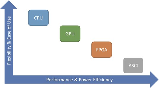
The decisive advantage of FPGAs is the ability to process data as soon as it arrives with minimal response delay.
Today FPGAs are widely used to build digital devices of various complexity and capabilities, for example:
1) devices with a large number of input/output ports (there are FPGAs with more than 1000 outputs (“pins”));
2) devices performing digital signal processing;
3) digital video audio equipment;
4) devices performing data transfer at high speed;
5) devices performing cryptographic operations, information security systems;
6) devices intended for the design and prototyping of ASIC;
7) devices that act as bridges (switches) between systems with different logic and supply voltage;
8) devices performing processing of radar information [8].
And also in recent years, FPGAs are actively used in the field of artificial intelligence (AI). FPGAs have great potential in AI applications with changing requirements. Unlike processors, they can be adapted to accommodate any change. FPGAs provide flexibility, continuous parallel computing, and a fairly favorable performance‐to‐power ratio.
3. FPGA as the basis of the AUV onboard computing environment
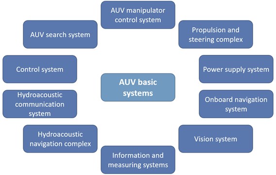
Having considered the list of FPGA applications, it can be assumed that this solution will be the most optimal for design of an onboard computing environment for AUV, since the FPGA solves any problem of the basic AUV systems (from the navigation system to a vision system using AI) effectively and quickly (Fig. 2).
Fig. 2General structure of the AUV
But, like any system, FPGA also has its disadvantages that must be considered – these are:
1) FPGA development is more complex than CPU and GPU development, but new development tools make this difference not so significant.
2) Programming – there are not enough FPGA developers on the market. The developer must have a deep knowledge of digital technology.
3) Lack of libraries for developing systems with AI – currently there are practically no machine learning libraries that support FPGAs. Nevertheless, work in this direction is actively carried out by the largest FPGA manufacturers and developers (Intel, Xilinx, Promwad and others).
4) High cost – considering the above, the cost of FPGA implementation automatically rises.
Consider an example of the implementation of a device for calculating a simple function , by means of Intel Quartus Prime, which will show us the main advantages and disadvantages of FPGAs. In this example, the numbers A, B and C will be positive and have a bit width of 4.
Fig. 3Data flow diagram (DFD) for the function
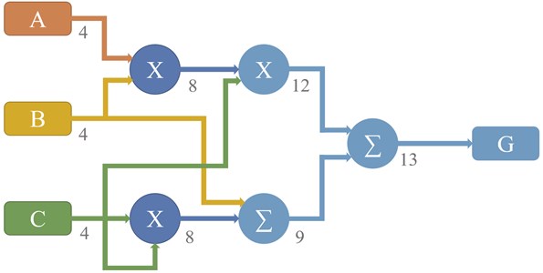
First, you need to make a calculation scheme, for example, in the form of a data flow diagram (Fig. 3). The diagram uses the following notation: rectangles for data sources (A, B and C) and data sinks (G), circles for arithmetic functions, and arcs for data. The bit depths of the numbers after the specified arithmetic operation are marked under each arc.
This DFD diagram will help us design a computing device that will calculate this function with the least number of clock cycles, thanks to the parallel calculation of the arithmetic operations of this function.
Fig. 4 shows a general diagram of a device calculating a given function , obtained with the help of Intel Quartus Prime.
Fig. 4Device for calculating a given function ABC+B+C2
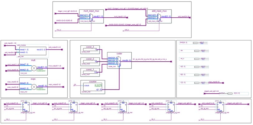
Fig. 5 shows a timing diagram for simulating the operation of the device. From this diagram, you can see that the function is calculated in 3 clock cycles with a clock frequency of 1 GHz. For example, a single‐threaded program written in C ++ for an x86‐based system shows a minimum result of 18 clock cycles at a CPU clock frequency of 3.7 GHz (measurements were taken using the __rdtsc() – integrated function of the Visual Studio 2019 C/C++ compiler).
Fig. 5Simulation of device operation
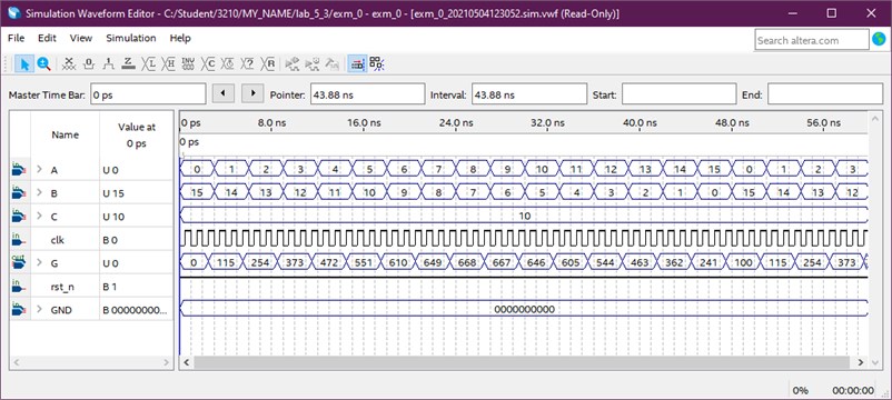
This comparison shows the high performance of FPGA in this task compared to the CPU, but at the same time this example shows one of the main disadvantages of FPGAs — complexity of development.
4. Conclusions
Summarizing all of the above, FPGA is a high‐performance system with low power consumption, with minimal response delay, with the ability to process signals from a large number of I/O ports and with the ability to apply artificial intelligence in various fields of ocean exploration. At the same time, the system will require a large investment in development due to the shortage of highly qualified specialists and the lack of universal tools for working with FPGAs. But in spite of the high cost of the development of onboard computing environments FPGA‐based, a comparative analysis revealed that the advantage of this technology is the parallel operation with a large data array, which is fundamental in the development of AUV onboard computing environments.
References
-
Adham Atyabi, Somaiyeh MahmoudZadeh, Samia Nefti-Meziani Current advancements on autonomous mission planning and management systems: an AUV and UAV perspective. Annual Reviews in Control, Vol. 46, 2018, p. 196-215, https://doi.org/10.1016/j.arcontrol.2018.07.002
-
Wynn R. B., Huvenne V. A. I., Le Bas T. P., et al. Autonomous Underwater Vehicles (AUVs): Their past, present and future contributions to the advancement of marine geoscience. Marine Geology, Vol. 352, 2014, p. 451-468, https://doi.org/10.1016/j.margeo.2014.03.012
-
Humphris S. E., Soule A. Vehicles for Deep-Sea Exploration. Encyclopedia of Ocean Sciences (Third Edition), Vol. 5, 2019, p. 21-30, https://doi.org/10.1016/B978-0-12-409548-9.11213-8
-
Inzarcev A. V., Lvov O. Y. Onboard computer networks of autonomous underwater robots. Modern Automation Technologies, Vol. 2, 2005, p. 68-74, (in Russian).
-
Salhi I., Poreba M., Piriou E., Gouet Brunet V., Ojail M. Chapter 8 – Multimodal Localization for Embedded Systems: A Survey, Multimodal Scene Understanding. 1st ed. Academic Press, 2019, https://doi.org/10.1016/B978-0-12-817358-9.00014-7
-
Rumyancev Y. FPGA. We understand how programmable logic circuits are arranged and why they are good. Xaker, Vol. 236, Issue 11, 2018, p. 8, (in Russian).
-
Tiete J., Domínguez F., Da Silva B., Touhafi A., Steenhaut K. MEMS microphones for wireless applications. Wireless MEMS Networks and Applications, 2017, p. 177-195, https://doi.org/10.1016/B978-0-08-100449-4.00008-7
-
Kurskij V. V., Sunka V. Y., Polynkova E. V. Programmable FPGA. International Scientific and Technical Conference on Materials, Equipment and Resource – Saving Technologies in Mechanical Engineering, Minsk, 2010, p. 255-259, (in Russian).
Cited by
About this article

