Abstract
The article provides а retrospective analysis of the emergence of prerequisites for the creation of designs of universal pumping units: from the first patents registered in the 1940s to modern technical solutions used at industrial facilities. The possibility of industrial application in the oil industry of fundamentally new types of vane pumps with а combined design of the impeller and rotor or the electric motor, which received а recent impetus to their spread with the development of electric motor technologies, is considered. The fundamental difference between these types or pump is the transmission of the torque to the impeller not through the shaft. but through the rim or the wheel, which is also the rotor of the eclectic motor. The absence or а shaft provides а number of advantages, in particular, it leads to an increase in suction capacity, an increase in pressure characteristics and an increase in operational properties – all this together increases the scope or industrial application of new types or pumps. One of the potential applications of а compact pump of the horizontal type can be the rocking to а frozen oil pipeline by tapping the coil at special points of the pipeline route. From the point of view to transporting high-velocity oil, the design of this type also looks promising; in addition, the possibly of influencing the transported medium by an electromagnetic field is noted. The possibility or using removable impellers of various types for а hollow pump-electric motor is considered, which can significantly increase the scope or application of new types of pumps.
1. Introduction
Until recently, torque transmission to the pumped medium was widely carried out using impeller rim instead of pump shaft only in helical-type pumps and progressing cavity pumps. For instance, this method was spread on several types of conveyors, which were used for pumping bulk materials by using rotating transport tubes with helical tape coils welded to inner wall surface. Industrial interests in torque transmission to impeller rim of vane’ pump was appeared recently in the 90s of the 20th centuries, as researching ways to combine pump with electric motor.
The main feature of the reviewed new types of the vane' pumps are in usage either rotating pump casing or impeller as moving part of the electric motor. In these types of pumps rotational torque is being transferred to the impeller through the cylindrical case rim. Sometimes these types of pumps are being called either rim – driven or shaftless, but several constructors use for the rotated pump casing such term as hollow-shaft.
First patents which weren’t widespread in production area appeared in 1940 [1], [2]. These patents described only main conception of the device, without considering its construction and characteristics. Realization of compact and efficient rim – driven pump become possible with development of modern science and electric engines [3]. There are at least 5 types of electric engines which could be used with our device: asynchronous, reaction, permanent magnet both continuous and alternate current, high voltage [4]. Dozens of companies had developed their variants of shaft less pumps, but only a few of them shared design of electric motor, bearings, and other main characteristics of construction because of commercial confidentiality, it was such companies as Rolls-Royce, Voith, Van der Velden and etc. Increased production of these types of pumps makes it possible to consider their usage in Russia petroleum area.
Advantages and disadvantages of new types of vane pumps-electric engines were analyzed in this paper, also it was determined sphere of their usage in main pipeline transportation of oil and petroleum products.
2. Generalized characteristics of shaftless vane pumps
Main feature of shaftless rim driven vane pumps-electric engines is in decreasing volumetric loss because of absence of shaft hole, it helps to avoid leakage of transported liquid. Moreover, efficiency factor is risen because of reducing energy losses on overcoming shaft inertia during start. One more advantage is compactness of the combined system compare to divided construction. Small dimensions could be achieved in case of usage modern electric engines with external electronic commutation. As disadvantage it could be considered increased cost of construction and repairment such types of pumps because of higher operational reliability and safety: flammable fluid is near to electrical coil, design complexity and etc. [3], [4].
Axial pumps of this type were first interested in in the marine industry as maneuvering propulsion device, where the main advantage was their compactness [4].
Rim-drive propeller thrusters have been known for a long time. They were used, for example, for the ships of the USSR “Valery Chkalov” and “Rodina”, built in the middle of the twentieth century in Germany [5]. However, only in recent years have such thrusters become widespread.
Fig. 1Application of shaftless axial flow pumps as ship thrusters [4]
![Application of shaftless axial flow pumps as ship thrusters [4]](https://static-01.extrica.com/articles/22288/22288-img1.jpg)
Fig. 2Mutual influence of the electric motor and the characteristics of the impeller [7]
![Mutual influence of the electric motor and the characteristics of the impeller [7]](https://static-01.extrica.com/articles/22288/22288-img2.jpg)
Attractiveness of rim driven axial pumps is provided by their hydraulic efficiency either reducing loss of head or completely removing them by decreasing size of the runner crown, as well as the absence of losses in gap between the impeller blade and the cylindrical pump casing. However, it’s important to conform hydrodynamic characteristics of impellers with engines characteristics in order to reach efficient construction as it could be seen at Fig. 2. It’s possible that impeller couldn’t run at optimal point for the engine, which reduces efficiency [6], [7].
In [8], the results of tests of axial pumps of traditional design and pumps with a rim drive are given, there was shown that usage of rim drive not only increased efficiency level but also zones of optimal operation of pumps became almost twofold as it could be seen at Fig. 3.
Fig. 3Efficiency of conventional and rim-driven axial flow pumps [8]
![Efficiency of conventional and rim-driven axial flow pumps [8]](https://static-01.extrica.com/articles/22288/22288-img3.jpg)
There are two versions of the rim driven pump with and without runner crown, both of solutions have their advantages, for instance axial pump with it has higher hydraulic efficiency because of reduced the effective interaction area of the pumped liquid flow with impeller.
In [9], rim-driven waterjet pump was numerically designed, also there was analyzation how type of the runner crown and just fixed vanes without it affect on the flow using a simple stationary CFD model. The results showed that the efficiency of the vane pump impeller without hub decreased by about 10 % due to energy losses in the center line.
However, hub usage increases impellers strength because all the blade ends are connected to the hub, so it can be built larger and create higher axial force.
Fig. 4Stress distribution on the blades for cases, when impeller blades fixed a) in the hub, b) in the rim, as well as c) in the hub and rim [3]
![Stress distribution on the blades for cases, when impeller blades fixed a) in the hub, b) in the rim, as well as c) in the hub and rim [3]](https://static-01.extrica.com/articles/22288/22288-img4.jpg)
a)
![Stress distribution on the blades for cases, when impeller blades fixed a) in the hub, b) in the rim, as well as c) in the hub and rim [3]](https://static-01.extrica.com/articles/22288/22288-img5.jpg)
b)
![Stress distribution on the blades for cases, when impeller blades fixed a) in the hub, b) in the rim, as well as c) in the hub and rim [3]](https://static-01.extrica.com/articles/22288/22288-img6.jpg)
c)
In [3], was presented the calculated relative loads for three types of axial pumps: a) shaft drive, b) rim-driven without hub, c) rim-driven with hub. Stress distribution is shown at the Fig. 4 level lines correspond to the part of the maximum stresses in each case.
As the obtained stress distributions show, the region of maximum stresses for rim axial pumps is displaced in the area around the blade joints. However, it should be noted that as the thickness of the rim fixed blade decreases, the place of maximum stress can shift to the middle radius of the blade.
If the blade is fixed on both sides, the maximum stresses are achieved near the hub and rim, but on opposite sides of the blade. In this case, it is found that the place of maximum stress is displaced towards the leading edge.
Peak stresses with conventional design are 1.5 times higher than with rim-mounted blades. The reduction in stress levels is achieved not only due to the thicker blade tip sections, but also due to the special distribution of the load on the propeller blades. Rim fixed blades are characterized by shorter force arms applied to the end sections and longer force arms applied to the root sections. Since the loads on the end sections are usually much higher than the loads on the root sections, the bending moment is lower for rim fixed vanes than for hub fixed vanes.
The stresses are significantly reduced when the blades are attached to both the hub and the rim. In this case, the stress values are approximately 1/4 of the stress values observed for rim fixed vanes.
Thus, the presence of a hub in rim-driven axial-flow pumps with a makes it possible to reduce the weight of the impeller and increase its efficiency due to the use of blades of smaller thickness [3].
The first developments in the application of axial pumps with a rim drive are presented in [10]: Such a pump provides a large flow and is easily reconstructed for new operating conditions, if necessary, since only the sleeve and the impeller with blades need to be replaced. Schematic view of the proposed shaftless pump could be seen at Fig. 5.
Fig. 5Schematic view of the proposed shaftless pump: 1 – inlet; 2 – outlet; 3 – casing; 4 – stator; 5 – rotor; 6 – sleeve for impeller installation; 7 – bearings; 8 – seals [10]
![Schematic view of the proposed shaftless pump: 1 – inlet; 2 – outlet; 3 – casing; 4 – stator; 5 – rotor; 6 – sleeve for impeller installation; 7 – bearings; 8 – seals [10]](https://static-01.extrica.com/articles/22288/22288-img7.jpg)
![Schematic view of the proposed shaftless pump: 1 – inlet; 2 – outlet; 3 – casing; 4 – stator; 5 – rotor; 6 – sleeve for impeller installation; 7 – bearings; 8 – seals [10]](https://static-01.extrica.com/articles/22288/22288-img8.jpg)
It is noteworthy that the increase in the impeller diameter, calculated by the authors from the similarity theory, increases the hydraulic efficiency. This fact indicates a good possibility of using such pumps in production.
New technologies for the development of electric motors, of course, lead to the emergence of shaftless centrifugal pumps. Although the combination of a pump with an electric motor was presented in early works [11], [12], the first prototypes of such pumps are already appearing today as it’s show at Fig. 6. At Tsinghua University (Beijing), a mathematical model of a shaftless pump with an impeller with a diameter of 40 mm was created and fluid flows in the flow path of the pump were simulated [13].
The absence of a shaft should also improve the hydraulic efficiency and suction capacity of new types of centrifugal pumps, but there is currently no research in this area.
Fig. 6Shaftless centrifugal pump with double suction: 1 – engine rotor; 2 – seal ring; 3 – cover; 4 – plug; 5 – outer case; 6 – pump casing; 7 – stator winding; 8 – permanent magnet; 9 – impeller
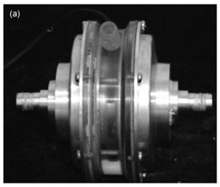
a) Photo of the pump model
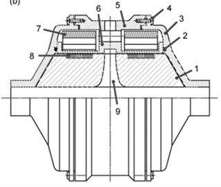
b) Schematic structure
3. Discussion
The increased suction capacity and improved pressure characteristics of the new types of shaftless pumps will, of course, improve their performance. However, their acquisition requires large capital expenditures. Therefore, to ensure the efficiency of their application, the design life of the technologies in which they can be applied must be long, such as for the main pipeline transportation of oil and oil products. Axial flow pumps with increased suction capacity can be used as booster pumps by selecting special impeller designs, up to screw or screw designs to further increase the suction capacity. Also, these compact pumps of both axial and centrifugal types can be used to swing a frozen oil pipeline by inserting a coil in special places of the pipeline route, where the pressure increase does not exceed the carrying capacity of the pipeline.
Pumps without a hub, or center shaft, can handle highly viscous oil without hindrance, and powerful electromagnetic stimulation will increase the fluidity of high-viscosity oil.
The use of removable impellers of various types for a hollow electric motor can significantly increase the field of application of new types of pumps. The design of a hollow electric motor, in which the removable impeller can be either centrifugal, axial or diagonal-flow, is waiting for its new researcher.
4. Conclusions
New trends in the development of technologies for the production of electric motors have prompted the improvement of vane pumps by combining them. In addition to the compact size, new types of impellers for such pumps have better hydraulic and strength characteristics.
The use of these advantages in the transportation of oil and petroleum products promises to give profitable prospects. Further research by the authors will be aimed at finding designs for impellers of shaftless vane pumps that meet the operational requirements of the main pipeline transport of oil and oil products.
References
-
Kort L., “Elektrisch angertriebene schiffsschraube,” Patent DE688114, Germany, 1940.
-
D. W. Brown, J. R. Repp, and O. S. Taylor, “Submersible outboard electric motor/propulsor,” Naval Engineers Journal, Vol. 101, No. 5, pp. 44–52, Sep. 1989, https://doi.org/10.1111/j.1559-3584.1989.tb00864.x
-
A. Y. Yakovlev, “Numerical design and experimental verification of a RIM-driven thruster,” in 2nd International Symposium on Marine Propulsors, 2011.
-
X. Yan, X. Liang, W. Ouyang, Z. Liu, B. Liu, and J. Lan, “A review of progress and applications of ship shaft-less rim-driven thrusters,” Ocean Engineering, Vol. 144, pp. 142–156, Nov. 2017, https://doi.org/10.1016/j.oceaneng.2017.08.045
-
Lebedev E. P. et al., Ship Steering Units. Sudostroenie, 1969.
-
S. M. Abu Sharkh, S. H. Lai, and S. R. Turnock, “Structurally integrated brushless PM motor for miniature propeller thrusters,” IEE Proceedings – Electric Power Applications, Vol. 151, No. 5, pp. 513–519, 2004, https://doi.org/10.1049/ip-epa:20040736
-
C. Pashias and S. R. Turnock, “Hydrodynamic design of a bi-directional, rim-driven ducted thruster suitable for underwater vehicles,” University of Southampton Ship Science Report No.128, Jan. 2003.
-
M. Lea, D. Thompson, B. Blarcom, J. Eaton, J. Friesch, and J. Richards, “Scale model testing of a commercial rim-driven propulsor pod,” Journal of Ship Production, Vol. 19, No. 2, pp. 121–130, May 2003, https://doi.org/10.5957/jsp.2003.19.2.121
-
T. P. Andersen, “Design of rim driven waterjet pump for small rescue vessel,” Master’s Thesis, 2014.
-
Schmirler, “The design of axial shaftless pump,” in EPJ Web of Conferences, Vol. 143, p. 02104, 2017.
-
Sabini Eugene P., “Shaftless canned rotor inline pipe pump,” United States Patent US 6,254,361 B1, 2000.
-
Shotaro Mizobuchi, Katsumi Sasaki, and Yoshikazu Kimura, “Pump with shaftless impeller,” United States Patent US 4,806,080, 1989.
-
Luo X. W. et al., “A novel shaft-less double suction mini pump,” Science China Technological Sciences, Vol. 53, pp. 100–105, 2010.
About this article

