Abstract
The dynamic characteristics of one of the centrifugal pump critical parts such as the rotor shaft are studied in the article whilst the highest level NASTRAN CAD PATRAN module was used to carry out the dynamic analysis. During the analysis a computational mechanical scheme has been compiled as well as force factors generating rotor vibrations have been determined. The axial, radial and hydrodynamic forces affecting the impeller and pump shaft have been calculated according to the analytical formula. Under the given boundary conditions in the FE model and the chosen method for determining the natural vibrations, a numerical solution of the equations of free and forced vibrations has been found using the algorithms of the NASTRAN program. The natural vibrations of the rotor have been determined using the Lanczos method. The dynamic stability of the shaft, the stress-strain state of the shaft and its displacement under static loads, the frequency and shape of the natural vibrations of the rotor necessary for the calculations have been determined. The amplitude-frequency characteristics of the system have been determined and analyzed for affection by external forces at the reverse and blade frequencies. Using the amplitude parameters of the forced oscillations, the dynamic gain of the rotor has been determined. Based on the amplitude-frequency parameters, the option of the number of blades for the working centrifugal impeller of the pump has been justified. The technique of computer simulation and determination of the vibroactivity parameters of a submersible centrifugal pump rotor shaft is given in the article.
1. Introduction
Vibration is the diagnostic sign of most failures during the pump exploitation. As a rule, failures are accompanied by the destruction of individual parts of the seal assemblies and rolling bearings as well as the centrifugal pump (CP) main parts failure. The most common defects in the parts of the CP are shown at Fig. 1.
To define vibration, it is necessary to study the dynamic characteristics of the oscillatory system and the natural forms and frequencies of oscillations, the response to external influence in the form of an AFC (amplitude-frequency characteristic) are at the first instance for the study [1].
Modeling is the basis of a theoretical study of the CP dynamics. Modeling of dynamic processes is used to determine the response of a mechanical system to external influences. External influences can be deterministic or random. Upon the previous fact, the response of a mechanical system is to be described by a periodic or random function respectively. When modeling dynamic processes, it is necessary to build a model that describes the movement of each point of a mechanical system depending on external influences which occurs as the main problem of the dynamics of machines [2]. The CP is a rotary unit the main elements of which are the shaft, impeller and bearings.
2. Statement of problem and research objectives
Performing the main function of the transmission of torque, the kinematic parameters of the rotor change in time while the rotor is considered as an oscillatory system. Centrifugal pump rotor makes interconnected and torsional oscillations in three mutually perpendicular directions.
Analytical methods for studying the oscillations of real rotors are very laborious. Therefore, numerical methods are used, in particular, the finite element method is applied. The method is based on the variational principles of mechanics, based on determining the minimum potential energy of mechanical system when the corresponding parameters are varied.
This method includes the following steps for solving dynamic problems: constructing a dynamic rotor model in a finite element form; identification of dynamic affects; determination of the rotor stress and strain state (SSS) parameters under static affect and supports parts’ reaction to the selected CP operation modes; calculation of the parameters of free and forced oscillations of the rotor [3].
3. The finite element model of centrifugal pumps
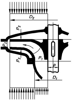
The approach for building dynamic models of the CP of this type is identical. A centrifugal multistage pump, which is used to leach uranium, was adopted as an object of study. The principal and dynamic scheme of rotor circuit of the CP of UPP 13-7/6 type is shown at Fig. 1.
Fig. 1Rotor schematic diagram a) principal scheme; b) dynamic scheme
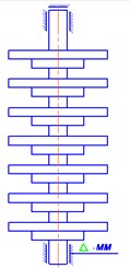
a)
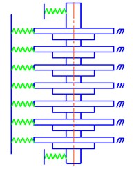
b)
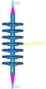
As far as the choice was made in favor of the FEM of the NASTRAN/PATRAN system for studying dynamic processes, let us present the rotor circuit diagram (Fig. 2) in the form of a finite element model. Schematic diagram displays the elastic-mass characteristics of the mechanical system of the “rotor-support parts”. There are several approaches for the creation of FE models [4]. First, we create the rotor geometry according to the working drawings (Fig. 3).
To build the FE model of the rotor let us use solid elements of the TET type. For the support parts modeling let us use the operating conditions, the upper end is connected by means of a finger coupling, the lower end is connected to a hydrodynamic bearing in the form of a layer of distilled liquid [5].
The feature of modeling in the program is the use of RBE2 elements connecting the node and the group of nodes with rigid rods, allowing to impose restrictions on movements along three axes and to set the rotation of the shaft around its axis (Fig. 2).
4. The theoretical provisions for boundary conditions definition for computer model of centrifugal shaft stress-strain statement
In the general case, the calculation of the shaft strength is determined by the joint action of bending from the radial force and from the axial pressure force transmitted to the shaft from the impeller. The calculation of the UPP 13-7/6 CP shaft for static strength has been carried out as a calculation of a beam in hinged-rigid supports using the constructed FE model (Fig. 3).
Fig. 2The finite element model of the CP rotor shaft
Let us compose a computational loading scheme for each of the operating modes of the CP (Table 2). During the operation of the CP the hydraulic radial force , the hydraulic axial force , the inertia force of the imbalanced mass of the centrifugal wheels and also the reaction of the rolling bearings and act on the shaft.
Using the principle of independence of the action of forces, we determine the type of loading under the action of the above forces. Under the action of the hydraulic radial force , the shaft bends in two planes, and the hydraulic axial force the shaft operates under tension and compression.
The loads acting on the rotor perpendicular to the axis are related to the transverse forces. Under the action of transverse loads, rotor vibrations are perturbed along the and axes. In this case, the center of gravity of each section moves along a closed path. Transverse loads are mechanical and hydraulic by their nature. The mechanical nature of the transverse forces acting on the rotor refers to kinematic, force and parametric affects.
Force action include centrifugal inertia due to rotor imbalance, shaft misalignment, manufacturing defects of couplings and rolling contact bearings. The kinematic effect appears as a result of a geometric disruption of the geometric shapes of the mantling bodies, in particular, the non-cylindrical nature of the mantling of the shaft and the rolling bearing, different sizes of the rolling bodies, waviness, faceting of runner, etc. [6]. Force disturbance is described as follows:
where – rotor mass, – angular rotation velocity, – specific imbalance (eccentricity).
The amplitude of the inertia of the imbalanced mass of the centrifugal wheels determination for the strength at a known residual unbalance of the wheel is possible using the following formula:
where is the permissible sufficient imbalance of the wheel, kg·m (for example, the expression “permissible residual imbalance of 100 g·mm means that for a wheel with a radius of 100 mm, external radius balancing should be performed with an accuracy of 1 g, which is technologically achievable), – angular rotation speed of the pump rotor, 1/s. the value of the eccentricities of wheels with different diameters are given in Table 1. [7].
To calculate the radial force from the imbalance, we used SolidWorks capabilities to determine the mass of a 3D model of a centrifugal wheel; these capabilities of modern CAD systems allow us to determine volume-mass characteristics of any bodies of complex geometric shape, in our case for seven wheel sections with directive vanes of mass 7.2 kg.
Table 1Eccentricity with different impeller diameters
Impeller outer diameter, mm | < 300 | 300-500 | 500-1000 | 1000-2000 |
Eccentricity, mm | 0.075 | 0.100 | 0.150 | 0.200 |
Therefore, Eq. (2) cannot be used, since it is given in the theory of rotor balancing, for the reason that centrifugal wheels are hollow, until they are filled with distilled medium, then to calculate the radial force in Eq. (2), an adjustment must be made so that the mass will be composed as the mass of the section adding the mass of the distilled liquid:
where – medium mass, – centrifugal wheel section mass.
The mass of sulfuric acid at a given feed has been determined by the formula:
where – outer diameter of the centrifugal wheel, m; – shaft diameter, m; – width of the meridian wheel section, m; – distilled liquid density, kg/m3.
Considering the principle of superposition of forces, the radial resultant force acting on the shaft was calculated as the sum of the forces from the imbalance at each stage of the rotor.
In addition, one of the causes of shaft deflection is the radial force. It represents the hydraulic force in the plane of the impeller, arising from the variable impact of the impeller and the guiduing tool (or guide vane). It varies in magnitude and direction depending on the pump flow rate and it acts on the shaft and bearings, Fig. 3 shows the direction of the distributed radial hydraulic force.
The hydrodynamic radial force acting on the CP rotor is divided into two components: static and dynamic. The static component of the radial force is a force averaged over time. The dynamic component of the radial force is caused by the non-stationary flow in the flowing part of the guide apparatus and causes pulsations of pressure and fluid velocity [8].
Fig. 3Direction and magnitude of radial forces
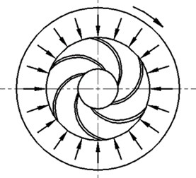
The complex nature of the spatial flow in the flow part of the pump and the viscous properties of the pumped liquid do not allow us to determine an accurate analytical dependence of the radial force on the feed. Therefore, analytical dependences of the radial force value on the feed of the CP are obtained on the basis of experimental data and the adopted simplifications. The derivation of the analytical formula of radial force is presented in the paper. For an approximate calculation of the radial force the following dependence is used [9]:
where – radial force coefficient, ( 0.36 admitted according [10]); – outlet wheel diameter, 0.515 meters; – outlet wheel width, 0.111 meters; – fluid density, 1000 kg per meter cubic; – gravity acceleration; – current head, meters.
5. Axial forces
The loads acting on the rotor along the axis are related to axial forces. In a cantilever type CP the rotor is affected by the axial force due to the pressure difference at the outer sides of the main and covering disks, which occurs due to the difference in their areas (Fig. 4(a)). In horizontal CP with a double-entry inlet impeller, the rotor is unloaded by the action of axial force, since the impeller is symmetrical to the vertical plane perpendicular to the axis.
Usually we separate pressures to acting on the external and to internal surfaces of the disks of the impeller. The unilateral inlet impeller is affected by the action of surface pressure forces directed along the axis. In order to determine the resulting axial load, it is necessary and sufficient to consider the pressures acting on the outer and inner surfaces of the main and covering disks (Fig. 4(b)).
Fig. 4Scheme of pressure distribution on the surfaces of the disks
a) Pressure distribution over the surface of the discs
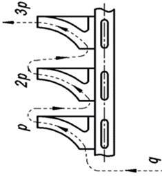
b) Pressure distribution in the pump stages
The complex nature of the flow and the viscous properties of the liquid make it difficult to determine the axial force, therefore, an analytical dependence in an approximate form is used. The axial force is determined by the formula below.
The axial force can be approximately determined as the difference between the pressure forces at the right and left sides in the range from to :
where — thrust force in N; – impeller inlet outer radius in meters; – shaft radius in meters; – pump head in meters, – fluid volumetric weight in kg per meter cubic [8].
Taking into account the fact that the CP is designed to pump sulfuric acid with density of 1050 kg per meter cubic, the axial and radial force values from the imbalance were found. Loading conditions and boundary conditions are listed in the data table for performing static and dynamic calculations.
Boundary conditions in the computational scheme are given in the Table 2.
Table 2Boundary conditions in the computational scheme
No | Parameter | Value |
1 | Material | steel |
2 | Modulus of elasticity | 2×10¹¹ Pa |
3 | Poisson’s ratio | 0.3 |
4 | Support 1 | Swivel hinge with rotation about an axis |
5 | Support 2 | Swivel hinge with rotation about an axis |
6 | axial | 1.2 kN |
7 | Radial hydraulic force | 105 N |
8 | Strength from imbalance of hinged parts | 8.4 N |
9 | Calculation type | Static |
As a result of calculating the static strength of the shaft, equivalent stresses has been obtained (Fig. 5(a)) as well as the values of the static shaft bendings (Fig. 5(b)).
The analysis of the results showed a sufficient safety factor at maximum feed, according to the diagram: = 34.6 MPA, 9.29×10⁻⁵ meters, allowable stress for steel is 450 MPA, safety factor amounted to 10.2.
Fig. 5Static strength of the rotor in maximum feed mode
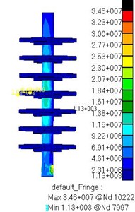
а) Equivalent stresses
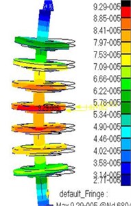
b) Diagram of displacements
6. Mathematical and computer modeling of free rotor vibrations
Free vibrations completely determine the dynamic properties of mechanical system and are of primer importance in the analysis of forced vibrations, therefore, using the finite element model let us determine the spectrum of eigenfrequencies of vibrations of the central rotor.
General equation of motion in matrix form is to be represented as follows Eq. (7). To describe the motion only under the influence of a restoring (elastic) force without taking into account energy dissipation, let us use the following equation:
where [], [] – matrix of masses (inertia) and rigidity of the system; , – generalized movements of knots and their derivatives.
In finite element analysis, as a rule, the unknowns are the displacements of the nodes of the FE model. To determine the entire displacement field in the FE model interpolation is used, that is, the values of the unknown displacement are calculated by means of the FE shape (polynomial) function. Depending on the type, each FE is assigned to the corresponding form function. Using of the shape function allows us to determine the displacement vector of any point inside the FE model.
Mathematically the definition of generalized displacements comes down to solve the system of algebraic equations. As a rule, the system of equations is solved by matrix methods. In this case, the rigidity matrices [] and masses [] in Eq. (8) of the FE model being analyzed are quadratic diagonal. In diagonal matrices, it is accepted that the mass is concentrated in the nodes of the FE model. The size of these matrices is equal to the number of degrees of freedom of all nodes of the model. Let us represent Eq. (7) in the following form:
Solution of the Eq. (8) is sought in the form [11]:
where – values of eigenfrequencies; – the full vector of nodal displacements of the system; – amplitude column matrix.
The full vector is a function of the independent displacement components and rotation angles with respect to the corresponding axes. The full displacement vector is represented in the following form:
By substituting Eq. (9) into Eq. (8) we obtain a homogeneous system of algebraic equations of the form [10]:
System Eq. (8) has a nonzero solution if the determinant is zero:
In this case, the problem is reduced to calculating the eigenvalues of the frequencies and the eigenvalues of the vectors of the generalized displacement , thus, determines the shape of the natural oscillations at the corresponding value of the frequency . By the given the boundary conditions in the FE model and the selected method for determining the natural vibrations we find the numerical solution of the system of algebraic Eq. (8) using algorithms of the NASTRAN program .The natural vibrations of the rotor are determined using the Lanczos method [11].
The Lanczos method is one of the matrix methods for solving systems of equations. It is used to calculate the eigenvalues of vibration modes. The method is especially effective for obtaining low frequencies which indicate the behavior of the model. The Lanczos method is based on an iterative method for solving systems of equations [12]. Let us study the natural oscillations of the rotor when installing it at hinged-rigid supports. Let us restrict ourselves to study the natural vibrations of the rotor only. The boundary conditions correspond to the Table 2. In the free oscillations frequency range from 0 to 4000 Hz the rotor has four forms of bending vibrations along the and axes, as well as one torsional vibration around (Fig. 6).
Table 3Free vibrations of the rotor on articulated rigid supports
Rotor waveform | Results | |
The form | Frequency of free oscillations Hz | |
1st form | Torsional | 200 |
2nd form | Bending | 1300 |
3rd form | Bending | 1393 |
4th form | Torsional | 2089 |
5th form | Bending | 3455 |
6th form | Bending | 3460 |
Fig. 6Forms of oscillation of the rotor on hinged-rigid supports
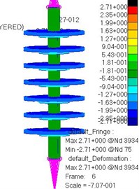
a) Form 1
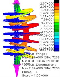
b) Form 2
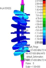
c) Form 3
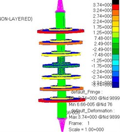
d) Form 4
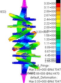
e) Form 5
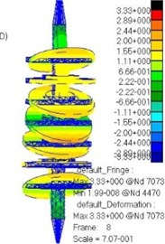
f) Form 6
In order to evaluate the values of bending, torsional and longitudinal (axial) shaft rigidity it is necessary to calculate the dynamic stability by the safety factor determination:
where – value of eigenfrequency of free oscillations; – the rotational velocity of the rotor is 50 Hz.
Table 4Free oscillations of the rotor
Oscillation form | Value of eigenfrequencies Hz | Actual margin of safety |
1st form torsional | 200 | 4 |
2nd form bending | 1300 | 26 |
3rd form bending | 1393 | 27.6 |
4th form bending | 2089 | 41.7 |
5th form torsional | 3455 | 69 |
6th form bending | 3460 | 69.3 |
To compare the obtained values of the eigenfrequencies of oscillations and the coefficients of dynamic stability, let us record the values of first 6 forms only (Table 4) as follows.
The minimum dynamic stability margin is equal to 4. The natural frequencies of the oscillations of the rotor calculation is made for rigid supports without taking into account damping.
According to the obtained values of the dynamic stability factor , it can be argued, that the bending, torsional and longitudinal (axial) rigidity of the UPP 13-7/6 pump rotor are sufficient for the system stability.
7. Mathematical and computer modeling of forced rotor vibrations
The CP operation is based on the transfer of mechanical energy of the flowing liquid during the force action of the blades on it. During operation all the parts of the CP are affected by dynamic influences of a different nature. A change in the mode of operation of the CP is accompanied by a change in load. The determination of dynamic effects is necessary to consider the issues of strength and forced oscillations of the CP rotor.
The main dynamic effects in the CP are the pressure forces from the flowing fluid in the moving parts of the CP. The magnitude and direction of the pressure forces acting on the rotor parts are determined by the nature of the fluid flow in the guiding tool, i.e. the impeller [13].
Forced vibrations of the CP are convenient to be represented graphically in the form of AFC for which it is necessary to solve the following equation:
where [], [], [] – matrix of masses (inertia), damping and system rigidity; , , – generalized movements of nodes and their derivatives; – generalized forces.
In matrix form, we represent Eq. (14) in the following form:
For the mathematical model of forced vibrations represented by Eq. (14), the corresponding computer model will be implemented by entering data such as the mass of the rotor [] with seven wheels mounted, the structural damping coefficient [], the system rigidity [] which depends on the module the elasticity of the steel material and from the wheel parts cross sections geometry, the component is to be described by the amplitude, i.e. the value of the hydrodynamic radial force and the pulsation frequency of this force equal to 400 Hz and 450 Hz for eight and nine centrifugal blades respectively.
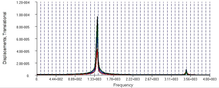
Under the influence of the unbalanced force at a revolution frequency of 50 Hz applied at the point of the center of mass of the rotor along the axis in a given frequency range from 0 to 4000 Hz the forced harmonic oscillations has been calculated. The result of the calculation of harmonic oscillations is presented in the form of AFC (Fig. 7).
In the frequency range under consideration, one harmonic appears at the lowest frequency equal to 1330 Hz, which corresponds to the second form of intrinsic bending vibrations of the rotor along the axis (Table 4), and the fifth eigenfrequency appears at a higher frequency of 3560 Hz so it can be ignored. The value of the amplitude of the oscillations of the rotor is equal to 2∙10-3 m (Fig. 7 the blue line is for the node in the center of the rotor).
Fig. 7AFC with the harmonic effect of unbalance force at a frequency of 50 Hz
In [15] the effect on the rotor of radial force at the blade frequency was found as following:
where – blade frequency, – rotational frequency, – number of centrifugal impeller blades.
When designing a centrifugal wheel, the number of blades was determined by the formula:
where – radius of midpoint of inlet blade width, – impeller outlet radius, , – inlet and outlet angle of the blade.
In the analytical calculation number of blades is 8.5, so the question of choosing the number of blades between 8 and 9 arose, and the problem was solved based on the dynamic characteristics of the rotor, that is, the response of the system to the action of a force at a frequency of 450 Hz (eight blades), and 400 Hz (nine blades).
The resonant states of the rotor of the central oscillator frequency response has been studied in the eigenfrequency range of the oscillation of the rotor 4000 Hz, the influence of the hydrodynamic force at a frequency 450 Hz is shown at Fig. 8.
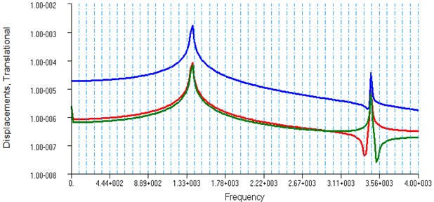
Fig. 8Rotor AFC at a frequency of 450 Hz
When the number of blades of a centrifugal wheel is eight, the response of the system to the influence of hydraulic force at a blade frequency of 400 Hz is as presented in the AFC diagram at Fig. 9.
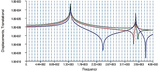
Fig. 9Rotor AFC at a frequency of 400 Hz
8. Analysis of forced vibration result
The analysis of the AFC of the rotor diagrams for the blade frequencies of 400 Hz and 450 Hz brings us to choose eight blade impellers, so the diagram at Fig. 9 has four harmonics with the largest amplitude of 10-3 m, while the diagram at Fig. 8 indicates the occurrence of two harmonics with a maximum amplitude of 10-4 m (Figs. 8, 9), that is, the dynamic forces arising at the 9th impeller cause high vibrational activity of the rotor, which leads to a loss of efficiency and a decrease in the service life of the technological system.
Analyzing the frequency spectra of vibration (Figs. 7-9) we determine the coefficient of dynamic gain at resonance. The coefficient is determined through the ratio of the amplitude of the forced harmonic oscillations to the static displacement under the action of a force equal to the amplitude of the harmonic excitation. The largest amplitude arises from perturbation by the imbalance force equal to 2∙10-3 m, according to the results of the SSS the static displacement is equal to 9.29∙10-5 m, thus, the dynamic gain at resonance is equal to 20. For pumps the dynamic coefficient according to [16] can be in the range of 20 to 25. According to [17] for rotor units the value of the coefficient should not exceed 50.
9. Conclusions
1) Computational mechanical scheme for determining the stress and strain state of the rotor shaft of a centrifugal submersible pump was composed.
2) The static loading factors of the pump were determined and the numerical values of the radial, axial, and unbalance forces were found.
3) The finite element analysis in the NASTRAN/PATRAN system allowed us to determine the Mises stress levels. The analysis of the results showed a sufficient safety factor at maximum feed, the maximum stress is 34.6 MPA, the static displacement is 9.29∙10-5 m, allowable stress for steel is 450 MPA and safety factor is 10.2.
4) The frequencies and forms of natural vibrations of the rotor shaft in the range from 0 to 4000 Hz were determined.
5) The values of the blade frequencies of the hydraulic disturbing force for a case of a centrifugal wheel with eight and nine blades were determined in theory, the AFC of the rotor at 400 Hz and 450 Hz were determined. Analysis of the results of the AFC made it possible to choose the impeller with eight blades according to the criterion of vibrational activity.
6) At a frequency of 50 Hz it has been found that the most dangerous rotor resonance occurs at the second natural frequency of 1330 Hz with an amplitude of 2∙10-3 m, in the form of bending vibrations from the imbalance of the mounted parts. In this case, with a high level of vibration, a sudden destruction of the shaft occurs at the mounting of the impeller due to an increase in static stress to a dangerous level.
7) The coefficient of dynamic stability 4-69.3 for six forms of natural vibrations is determined, the range of coefficients indicates sufficient bending and torsional rigidity of the rotor shaft.
8) Based on the results of the AFC, the dynamic gain coefficient 20 was determined, which corresponds to the standard values for the pumps.
References
-
Lienau W. Early optimization of large water transport pump casing. Sulzer Technical Review, Vol. 2, 2005, p. 4-7.
-
Levitsky N. I. Oscillations in Mechanisms. Science, Moscow, 1988, p. 336, (in Russian).
-
Zhovdak V. A. Oscillations of Rotating Rotors. NTU “KhPI”, Kharkov, 2001, p. 80, (in Russian).
-
Zhilkin V. A. The ABC of Engineering Calculations in MSC Patran-Nastran-Marc. Study Guide, Prospect of Science, St. Petersburg, 2013, p. 572, (in Russian).
-
MSC Patran User’s Guide, 2005.
-
Barkov A. V. Monitoring and Diagnostics of Rotary Machines by Vibration. SPbGMTU, St. Petersburg, 2000, p. 169, (in Russian).
-
Yamamoto T. Linear and Nonlinear Rotordynamics: a Modern Treatment with Applications. John Wiley and Sons, 2013.
-
Kelzon A. S., Zhuravlev Yu N., Yanvarev N. V. Calculation and Design of Rotary Machines. Mechanical Engineering, Leningrad, 1977, p. 288, (in Russian).
-
Majan Gantar, Dussn Florjancic, Brane Sirok Hydraulic axial thrust in multistage pumps-origins and solutions. Journal of Fluids Engineering, Vol. 124, Issue 2, 2002, p. 336-341.
-
GOST 17398-72 (State Standard). Pumps Terms and Definitions. Publishing House of Standards, Moscow, 1989, p. 35, (in Russian).
-
Ualiev G. U., Bisembaev K., Omіrzhanov Zh M. Terbelister Theories Study Guide. KazNPU named after Abay, 2009, (in Kazakh).
-
Ginesin Yu L. The Use of MSC NASTRAN for the Analysis of Rotor Dynamics. MSC Software, Moscow, 2000, p. 28, (in Russian).
-
Lomakin A. A. Centrifugal and Axial Pumps. Mechanical Engineering, Moscow, 1966, p. 364, (in Russian).
-
Goldin A. S. Vibration of Rotary Machines. Mechanical Engineering, Moscow, 2000, p. 344, (in Russian).
-
Donat V. G. Fundamentals of the Rational Design of High-Pressure Centrifugal Multistage Pumps of Power Plants. Ph.D. Thesis, St. Petersburg, 1997, p. 303, (in Russian).
-
Sokolov E. V. Modeling and Research of Dynamic and Hydrodynamic Processes in Centrifugal Pumps of Mass-Feeding Systems of Paper Machines. Ph.D. Thesis, Ekaterinburg, 2008, p. 188, (in Russian).
-
Sokolov E. B. Dynamic processes, loading parts of: centrifugal chemical pumps. Pumps and Equipment, Vol. 2, 2006, p. 22-24, (in Russian).
About this article

Madina Isametova – setting the task and research goals and development of a calculated mechanical scheme, analytical determination of boundary conditions: forces, dynamic indicators, i.e. the frequency of pulsation of forces, analysis of results. Beknur Omarbekov – computer simulation of the strength of the rotor of a centrifugal pump in NASTRAN, analysis of results. Ulan Angarbekov – creating 3D models in a CAD system. Rollan Nussipali – computer simulation of the problem of the amplitude – frequency response of the shaft-wheel system in NASTRAN, technical support of the publication. Aysen Isametov – computer simulation of the problem of the amplitude – frequency response of the shaft-wheel system in NASTRAN, translated into English, analysis of results.
