Abstract
The expanding packer is a commonly used packer, which is widely used in the process of oil and gas production. Taking the most commonly used K344 hydraulic expansion packer as the research object, using SolidWorks and ANSYS Workbench software to establish a two-dimensional finite element model of the K344 packer rubber cylinder, carry out stress analysis on the packer rubber cylinder, and obtain the packer rubber cylinder Von Mises stress and contact stress nephograms. The research results show that when the packer is in the working state of internal pressure of 20.0 MPa, the stress level of the upper and lower rubber cylinder seats is the highest, and the maximum Mises stress is 54.86 MPa; the stress level at both ends of the rubber cylinder is the highest, up to 43.465 MPa, and the strain energy density on both sides is the largest; when the packer is in the working state, the shoulder deformation is the largest, with the increase of the pressure, the deformation trend slows down, and the strain energy density has a linear relationship with the working pressure. The obtained results can provide a theoretical basis for the structural design of the expandable packer.
Highlights
- The maximum Mises stress was Mises stress at 54.86 MPa when the packer was operating at 20.0 MPa internal pressure. The stress level at both ends of the cylinder is the highest, up to 43.465 MPa, and the strain energy density at both sides of the cylinder is the largest.
- When the pressure inside the packer reaches nearly 20 MPa, the contact part of the packer rubber cylinder and the casing basically covers the whole middle section of the rubber cylinder, which can be well sealed to achieve the setting effect.
- When the packer is in working condition, the packer shoulder deformation is the largest. With the increase of pressure, the deformation trend decreases, and the relationship between the strain energy density and the working pressure is basically linear.
1. Introduction
Packer is widely used in the process of downhole operation. The packer rubber cylinder is one of the key parts of the packer to realize the downhole oil and gas stratification. The pressure of the rubber cylinder causes radial expansion and contact with the casing, so as to realize the sealing annulus and stratification. Because of the high cost of experiments, and with the development of numerical simulation technology, the method of using finite element software for engineering design and solving engineering problems has been gradually applied. The packer rubber cylinder is made of rubber material and has nonlinear characteristics, which makes the finite element analysis of the cylinder difficult. Thomas et al. proposed that the load capacity of the packer rubber is a function of the pressure (or stress) that exists during the sealing process. To achieve and maintain the seal, the pressure (or stress) should be greater than the working value. The maximum contact pressure between the rubber and the casing will directly determine the quality of the packer seal. The finite element model of the developed K344 expansion packer was established, the stress of the packer rubber cylinder was obtained by loading calculation, and the shoulder of the packer was analyzed in detail. The calculation results can provide a reference for the design of packer rubber cylinder.
2. Numerical calculation model
2.1. Working principle
The working principle of the packer can be briefly described as follows: Under the action of axial load, the rubber cylinder constantly deforms and expands to seal the annulus between tubing and casing. In the process of deformation and expansion, a certain contact stress is formed between the rubber cylinder and the casing wall to ensure its sealing, to achieve the purpose of isolating the production layer, isolating the well fluid pressure and preventing the pressure and fluid interaction between different production layers.
2.2. The geometric model
Packer rubber cylinder, center pipe, casing, rubber cylinder seat and other parts are rotating body parts, and the load is axisymmetric distribution. In order to reduce calculation amount and save calculation time, a two-dimensional axisymmetric model is established for calculation, the model is shown in Fig 1. 35CrMo steel is used for casing, center pipe, rubber cylinder seat and other metal materials. See Table 1 for geometric dimensions and material parameters.
Fig. 1Schematic diagram of calculation model

Table 1Calculate the parameters of the model
The name of the structure | Outer diameter / mm | Inside diameter / mm | Modulus of elasticity / MPa | Poisson’s ratio | ||
Rubber cylinder | 113 | 83 | 16.95 | 0.49 | 1.8743 | 0.93715 |
Casing | / | 123 | 2.1E+5 | 0.28 | / | / |
The center pipe | 83 | / | 2.1E+5 | 0.28 | / | / |
Rubber cylinder seat | 113 | 83 | 2.1E+5 | 0.28 | / | / |
2.3. Finite element model and cylinder constitutive model and parameters
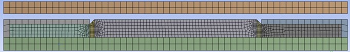
Based on the grid division standard and grid control method, the calculation accuracy and calculation cost are considered comprehensively. The overall grid type is quadrilateral dominated grid, and the rubber cylinder is the main analysis element and has the characteristics of large deformation, so the rubber cylinder grid is appropriately refined. The mesh of other metal components is thicker than that of the cylinder. The total number of grids is 1090 and the number of points is 3724. Meshing is shown in Fig 2.
Fig. 2Meshing diagram
There are many studies on the constitutive model of rubber. Phenomenological theory assumes that the material has isotropy and incompressibility, and uses strain energy density function to describe the constitutive model:
where: , , represent the Cauchy-Green first, second, and third deformation tensor invariants, respectively.
Mooney-Rivlin model is a commonly used constitutive model, which can be applied to the mechanical behavior of most rubber materials, and its strain energy density function is:
where: and represent the material parameters of the Rivlin model.
When the material is incompressible, the Rivlin coefficient is related to the elastic modulus of the rubber as follows:
where: the ratio of to is a constant, ranging from 0.25 to 0.5.
The elastic modulus of the rubber cylinder is 16.95 MPa, and the ratio of to is 0.5. According to Eq. (3), it can be calculated that 1.8743 MPa, 0.93715 MPa.
2.4. Boundary conditions and loads
According to the working conditions, the boundary conditions are as follows :(1) The upper and lower ends of fixed casing and central pipe are fixed; (2) Fix the upper end of the rubber cylinder seat and the lower end of the rubber cylinder seat; (3) Binding constraints are imposed on the rubber cylinder seat and the central pipe; (4) Binding constraints are imposed on the upper and lower ends of the rubber cylinder with the upper and lower rubber cylinder seat respectively; (5) The rubber cylinder is in contact with the central pipe, the surface of the casing and the rubber cylinder seat, and the friction factor is 0.3. The normal contact is set as hard contact; (6) Pressure load is applied inside the rubber cylinder.
3. Structural stress and strain analysis of expansion packer
3.1. Stress analysis
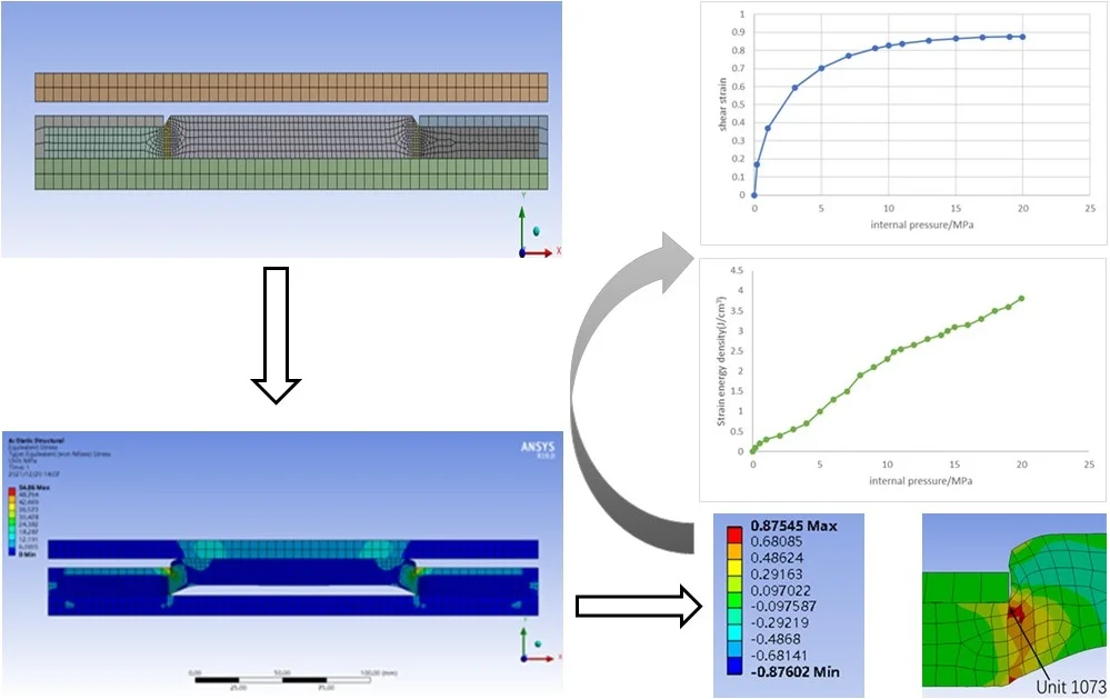
The stress field distribution of the packer assembly under 20.0 MPa internal pressure was calculated, as shown in Fig. 3. It can be seen from the figure that the stress of metal component is significantly higher than that of rubber cylinder, and the stress level of upper and lower rubber cylinder is the highest, and the maximum Mises stress is 54.86 MPa. Generally, the yield strength of 35CrMo material is 835 MPa, and the safety factor is 15.22. Since this force is primarily static, achieving this factor of safety is generally considered safe.
Fig. 3Mises stress field distribution of packers
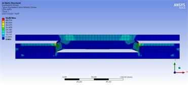
Fig. 4Mises stress field distribution of rubber cylinder
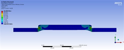
Fig. 4 shows the Mises stress field distribution of the rubber cylinder at the internal pressure of 20 MPa. It can be seen that the stress level at both ends of the middle segment of the rubber cylinder is the highest, up to 43.465 MPa. The stress distribution is more uniform in the middle part of the rubber cylinder, and the stress gradient is larger in the smaller areas at both ends of the rubber cylinder.
3.2. Strain analysis
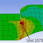
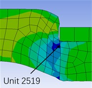
When the internal pressure is 20 MPa and the packer is in the working state, the area with the largest deformation of the rubber cylinder appears at the upper and lower ends of the rubber cylinder. Fig 5 clearly reflects the position of the maximum strain with the locally enlarged shear strain distribution cloud map, and marked the position of the maximum strain element with the unit number, namely the No. 1073 unit at the upper end and the No. 2519 unit at the lower end. The characteristic of easy deformation of the rubber cylinder shoulder is verified by finite element analysis, which provides a theoretical basis for the design of the packer rubber cylinder structure.
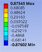
Fig. 5Locally enlarged shear strain distribution cloud map
a)
b)
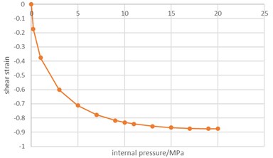
Fig. 6Variation of shear strain with internal pressure
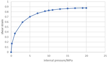
a) Variation of shear strain with internal pressure of unit 1073
b) Variation of shear strain with internal pressure of unit 2519
Fig. 6(a) shows that the shear strain of unit 1073 increases monotonically with the increase of internal pressure, and its change curve shows obvious nonlinear characteristics on the whole. When the internal pressure is small, the shear strain increases rapidly with the increase of the internal pressure. When the internal pressure exceeds 5.0 MPa, the shear strain increases with the increase of internal pressure is obviously slowed down, but the shear strain increases linearly with the increase of internal pressure. When the internal pressure reaches 20 MPa, the engineering shear strain reaches 0.87545.
Fig. 6(b) shows the variation of engineering shear strain with internal pressure in unit 2519, which is similar to that in unit 1073. When the internal pressure reaches 20 MPa, the engineering shear strain of unit 2519 reaches 0.87602. It can be seen that the shear deformation degree of unit 1073 is slightly smaller than that of unit 2519.
Fig 7 shows the forces between the rubber cylinder and the casing under different pressures. When the pressure reaches 0.2 MPa, the force between the rubber cylinder and the casing exceeds 0.3 MPa, then the rubber cylinder starts to unseal, which can play an initial effect of sealing the annulus. However, this situation is only when the contact between the two parts is less, when the internal pressure reaches nearly 20 MPa. The contact part between them basically covers the whole middle section of the rubber cylinder, and the situation can be well sealed to achieve the setting effect.
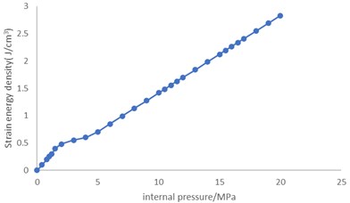
Fig. 8 and 9 show that, different from shear strain, strain energy density increases significantly with the increase of internal pressure, which is nearly linear in general. When the internal pressure reaches 20.0 MPa, the strain energy densities of unit 1073 and unit 2519 reach 3.81 J/cm3 and 2.83 J/cm3, respectively, which are very high in terms of strain energy densities.
Fig. 7Contact stress diagram on rubber cylinder under different pressure
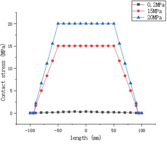
Fig. 8Variation of strain energy density of unit 1073 with internal pressure
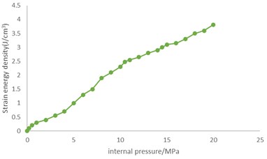
Fig. 9Variation of strain energy density of unit 2519 with internal pressure
4. Conclusions
Through the above analysis and calculation, the following conclusions are obtained:
1) The maximum Mises stress was Mises stress at 54.86 MPa when the packer was operating at 20.0 MPa internal pressure. The stress level at both ends of the cylinder is the highest, up to 43.465 MPa, and the strain energy density at both sides of the cylinder is the largest.
2) When the pressure inside the packer reaches nearly 20 MPa, the contact part of the packer rubber cylinder and the casing basically covers the whole middle section of the rubber cylinder, which can be well sealed to achieve the setting effect.
3) When the packer is in working condition, the packer shoulder deformation is the largest. With the increase of pressure, the deformation trend decreases, and the relationship between the strain energy density and the working pressure is basically linear.
References
-
Liu Ming, Jiang Wenjie, Zheng Ting, Zhao Lin, Chen Tao, and Zhang Jie, “Analysis of influencing factors on sealing performance of rubber cylinder of expandable packer,” (in Chinese), Journal of Sichuan University of Light Chemical Technology, Vol. 35, No. 1, pp. 67–73, 2022.
-
B. Li, D. Lu, and Z. Zhang, “Analysis of mechanical properties of wave packer rubber,” (in Chinese), China Petroleum Machinery, Vol. 35, No. 4, pp. 828–833, Aug. 2018, https://doi.org/10.11776/cjam.35.04.b026
-
C. Chen, Y. Lei, D. Liu, Y. Yin, T. Wang, and X. Li, “Application of smart packer technology in underbalanced completion,” in IADC/SPE Asia Pacific Drilling Technology Conference and Exhibition, Jul. 2012, https://doi.org/10.2118/155888-ms
-
Ma Li, “Overview of the research status of expanded packer rubber cylinder,” (in Chinese), Information Recording Materials, Vol. 17, No. 5, pp. 6–7, 2016, https://doi.org/10.16009/j.c
-
A. E. Verisokin, V. A. Vasil’Yev, and T. A. Gun’Kina, “Packer design research used in hydraulic fracturing,” IOP Conference Series: Earth and Environmental Science, Vol. 378, No. 1, p. 012106, Nov. 2019, https://doi.org/10.1088/1755-1315/378/1/012106
-
M. Alva and A. Alfaro, “Non conventional sucker rod pumping for slim hole wells,” in SPE Latin American and Caribbean Petroleum Engineering Conference, Mar. 2001, https://doi.org/10.2118/69550-ms
-
B. S. Lee and E. I. Rivin, “Finite element analysis of load-deflection and creep characteristics of compressed rubber components for vibration control devices,” Journal of Mechanical Design, Vol. 118, No. 3, pp. 328–336, Sep. 1996, https://doi.org/10.1115/1.2826888
-
Shapkin N. A., Nagumanov M. M., and Tsybeev I. V., “Sealing element of a packer,” 2011 Stalemate, Russian Federation No.2.473780, 2013.
-
R. Evers, D. A. Young, G. W. Vargus, and K. Solhaug, “Design methodology for swellable elastomer packers in fracturing operations,” in Offshore Technology Conference, May 2009, https://doi.org/10.4043/20157-ms
-
M. Kleverlaan, R. H. van Noort, and I. Jones, “Deployment of swelling elastomer packers in shell E&P,” in SPE/IADC Drilling Conference, Feb. 2005, https://doi.org/10.2118/92346-ms
About this article

