Abstract
In many areas of the industry, especially in the aviation sector, mechanical components have to work under harsh environmental conditions. In addition to being exposed to extreme environmental conditions due to the environment in which they operate, the basic components of aircraft have to take into account many engineering details such as high strength expectations, speed and impact problems under the influence of hard particles. In addition, the geometries of parts in aircraft can be quite complex and detailed shapes. For this reason, it makes sense to utilize different manufacturing processes to create the final shapes of the components. In this study, a research was carried out to determine the solid particle erosion wear behaviour of In718 test specimens representing the material properties of jet engine turbine blades in aircraft by alternative manufacturing methods and to interpret the results obtained by performing experiments. In718 alloys with horizontal (0°), vertical (90°) and angular (45°) orientation were produced by selective laser melting, a layered powder-based additive manufacturing method, and test specimens were produced by casting, a conventional method. These specimens were subjected to solid particle erosion tests using three different sizes (500 g, 1000 g and 1500 g) of Al2O3 abrasive particles at 30° impact angle. Surface topography and macroscope images were used to interpret the results of the surface differences obtained at the end of the experiments. Consequently, the layer orientation in additive manufacturing and the additive manufacturing method were compared with parts produced by a conventional method in terms of erosion rate. In addition, it was concluded whether the surface damage that occurs in erosive wear depending on the impact angle has a ductile, semi-ductile or brittle character.
Highlights
- Experiments were conducted on In718 specimens produced via Selective Laser Melting and Casting.
- SLM specimens are manufactured at different orientation angles 0°, 45°, and 90°.
- Erosion tests were carried out using 500 grams, 1000 grams and 1500 grams of abrasive solid particle.
- Surface topography and macro-scale images were used to characterize the surface damage on samples.
- It is understood that the additive manufacturing orientation angle factor has an effect on wear behavior.
1. Introduction
Mechanical components are subject to solid particle erosion wear in many industrial applications. Solid particle erosion wear can be observed in many areas such as gas turbine engine compressor blades in aerospace applications, metal parts like wheels and front panels in automotive industry, conveyor systems in the factory environment or plastic injection machine components [1]. These applications have a primarily metal-based material structure and complex part geometry. Metallic and complex geometry parts are difficult and costly to manufacture using traditional methods. Many production processes may be required to create the final shape [2]. In this direction, developments in recent years have led to new manufacturing methods and additive manufacturing methods known as layered manufacturing have been developed. Additive manufacturing technologies are becoming popular today thanks to its advantages such as creating the final part geometry in a single operation and responding to need for rapid prototyping in critical applications such as aerospace.
When aviation applications and aircraft are examined, compressor blades have a highly curved shape and amorphous material structure in terms of part geometry in gas turbine engines [3]. Powder based additive manufacturing methods facilitate production of such parts. In addition, suitabiliy of powder additive manufacturing techniques for aircraft is also important in terms of material utilization. Titanium and nickel alloys are used in many critical components of aircraft other than engine compressor blades. In the known literature, Ti6Al4V or Inconel 718 and 625 nickel alloys are used in aircraft mechanical components such as coolant gas pipe, high pressure turbine disc, fan body, fan transmission shaft [4]. Since machining titanium and nickel alloys by machining or other routine manufacturing processes is time consuming and costly, powder based additive manufacturing can be used to produce these components.
When operating environment of the aircraft jet engine structure is considered, mechanical components inside vehicle can interact with hard solid particles. As a result of the abrasion caused by collision of the blade structure in the engine with solid particles in relative motion againts it, structure is damaged and becomes unusable below expected service life [5]. Therefore, it is necessary to examine erosive wear of the structure. The investigation of the erosion wear of Inconel 718 nickel alloy that subject of this study is derived from this.
While In718 alloy can from whole structure, it can also be used as a coating material on the structure by mixing various powder materials into it in powder form. In718 coating also has its counterpart in various sectors, especially aerospace [6-9]. The behaviour of structure due to solid particle erosion of material in the structure is among topics investigated in the literature. In a study, In718 alloys produced by an additive manufacturing method known as selective laser melting (SLM) were heat treated in three different ways: double aging, double aging and solid solution, double aging and solid solution and homogenization heat treatments. As a result of tests, erosion mechanism of three different structures and erosion rates depending on particle impact angles were discussed. Consequently, it was observed that wear peaks at 45° impact angle [10]. Academic studies have diversified by including many parameters in research on the subject. Erosive behaviour of In718 alloys at high temperatures has been investigated [11, 12]. When studies are examined, In718 alloy produced by additive manufacturing has been used both as entire structure and as a coating material by ceramic or various materials into steel layer. Solid particle erosion tests were performed on obtained samples at various impact angles under effect of 400°C-800°C high temperatures. Within scope of common result obtained from the studies, it was observed that weight loss and erosion rate increased depending on temperatures increased [13, 14].
In718 nickel alloys are widely used in aviation industry. Factors such as high strenght, resistance to high temparatures and corrosion resistance of material provide reason for material to be preferred in high altitude environment conditions. Micron sized solid particles cause material to be subjected to erosive wear in environment. During collision with hard particles, fracture mechanisms such as crack initiation and lip formation start to develop on surface. Lip formation, platelet detachment and crack sharpening mechanisms predominantly occur on surface at an impact angle of 90° in solid particle erosion behaviour [15, 16]. The positive contribution of these emerging damage mechanisms is to delay rate of erosion. Fragmentation resistance increases, in components where these damage mechanisms occur. The study was conducted at room temperatures and damage mechanisms such as crack lip formation occured at 90° impact angle. However, when high temperatures effects are included, these fracture mechanisms can occur at different impact angles. In a study, solid particle erosion experiments were performed at high temperatures and lip formation, cutting and creep mechanisms occured at 45° impact angle [17, 18]. Consequently, many parameters such as temperatures, impact velocity, abrasive and abraded material, heat treated structure, coating, particle size can affect behaviour in various aspects in erosion wear behaviour studies.
One of main topics of this study is behavior of structure under influence of erosion. The behavior of surface as a result of solid particle erosion varies from ductile to brittle. Ductile or brittle behavior is observed on surface depending on abrasive particle impact angle. In the literature, collapse like plastic deformation is observed at low impact angles (0°-30°) due to ductile behavior, while brittle damage occurs at relatively high impact angles (60°-90°). Semi brittle/semi ductile behavior may occur at intermadiate (30°-60°) values [19]. There are review studies on damage and behavior of the material as a result of erosion wear. In the investigated studies, erosion included wear was investigated by using In718, ceramic and nanocomposites as coating materials for ductile and brittle main structures. In experiments conducted by including effect of high temperature in the study, it was concluded that wear resistance was highest in nanocomposites coating and material could not show its own properties due to coating [20].
Experimental studies to determine ductile or brittle behavior due to erosion are scarce. In this study, behavior and erosive wear mechanism of In718 specimens produced by additive manufacturing and conventional methods at 30° impact angle were investigated. In this way it is thought that an original source has been added to the literature.
2. Material and methods
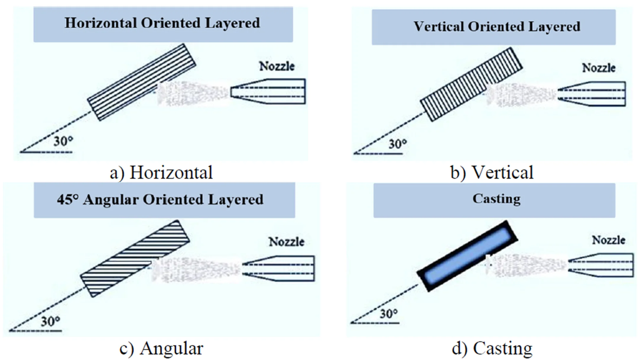
In this study, solid particle erosion tests were performed at room temperature on In718 alloys produced with various angular orientations by a powder based additive manufacturing methods and In718 alloys produced as castings. Selective laser melting (SLM) was used to create an angular difference between layers in horizontally (0°), vertically (90°) and angularly (45°) oriented specimens, and effect of orientation on solid particle erosion wear was investigated, as well as ductile and brittle behavior of surface as a result of erosion. Three different experiments were performed in order to investigated effect of specimens variety on amount of wear, and also experiments were performed at 30°, 45°, 60°, 90° impact angle with use of 500 gr. Of abrasive to determine ductile, brittle and semi ductile. 500 gr, 1000 gr and 1500 gr abrasive particles were used in experiments conducted at an impact angle of 30°. In addition, results were compared with the results obtained from In718 alloy produced by traditional methods (castings) and additive manufacturing was compared against casting. Fig. 1 shows images of un-worn specimens obtained. The erosion behavior between specimens with different manufacturing methods and orientations was compared by means of experiments performed at an impact angle of 30°. Ductility and brittleness were characterized in experiments with multiple impact angle.
Fig. 1In718 non-wear test specimens geometries
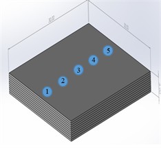
a) Horizontally oriented additive manufacturing (Y)
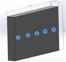
b) Vertically oriented additive manufacturing (D)
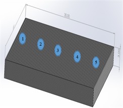
c) 45° angle oriented additive manufacturing (A)
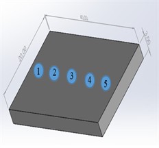
d) Produced with traditional (casting) method (KOAPS.064)
The specimens were subjected to erosion tests at an impact angle of 30° in order to investigated ductile or brittle behavior of obtained specimens and to investigated how differences in orientation of layers will affect erosive wear mechanism. By comparing results obtained from conventionally produced In718 alloys with additive manufacuturing specimens produced by SLM on the same scale; difference in ductile and brittle behavior as well as wear mechanism was compared.
Erosion value measured as a result of solid particle erosion tests was determined as the weight loss of samples. Difference between weight of samples before abrasion and after abrasion was determined and erosion value was obtained in this way using a precision balance with a sensitivity of 1 in 10000. Since effect of surface hardness and roughness on wear mechanism is also known in literature, rockwell hardness and surface roughness were also measured from surfaces of specimens and erosion wear results were evaluated [21]. After graphing erosion values expressed in weight loss, surface topography and macroscope images were taken from surfaces of samples. The results obtained were interpreted from various aspects and study was concluded. Solid particle erosion test parameters according to standards are given in Table 1.
Table 1Solid particle erosion wear test parameters
Sample material and production method | In718 alloy produced by additive manufacturing in horizontal, vertical and angled orientation and In718 alloy produced by casting (conventional) |
Abrasive particle material | Al2O3 |
Abrasive particle size (micrometer-µm) | 850 |
Abrasive particle amount (gram-gr) | 500-1000-1500 |
Particle impact angle (Degree°) | 30 |
Particle flow pressure (bar) | 3 |
Temperature (°C) | 22 (Room Temp.) |
Experiments were performed with parameters given in Table 1 and results were evaluated.
3. Erosion test setup
The test machine required for conducting solid particle erosion wear test activites is customized and tailor made. Finding a manufacturer is difficult in global market. In this context, the test machine used in experiments is located in Konya Technical University and device developed during doctoral process. One of most important advantages of tester is that it allows erosion tests to be performed at high temparatures, but since temperature effect was not considered in this study, the advantages of tester to provide high temperatures was not utilized. Room temperature was used in Experimental process and effect of production method and manufacturing differences on erosion was investigated. The experiments were carried out on erosion wear test machine schematically shown in Fig. 2 with solid particle erosion test parameters given in Table 1.
The tester capability includes possibility to increase temperature level to 700 °C and flow pressure of particles hitting surface up to 4 bar. In this study, effects of high temperature and speed were not investigated, but behaviour of material and orientation differences againts erosion and wear were questioned.
4. Results
Two mechanism influencing erosive wear are hardness and surface roughness. These two parameters will have an impact on the interpretation of the result. The samples are numbered in specimens’ images in Fig. 1. Since hardness results may differ between outhermost and middle, hardness was measured from outhermost to the inside. Since the wear zone of specimens is in middle of specimens, measurements numbered 3 are critical and surface roughness was also taken from this region. Hardness is an important parameter in the study of tribological wear mechanisms. When two parts are in relative motion againts each other, it can be seen that hard material wears less, while soft material easily deteriorates its surface due to developments of an adhesive wear mechanism. Particles hitting surface affect abrasion of sample surface in solid particle erosion behavior. It is also an important factor in ductile and brittle behavior on surface. Roughness value is also one of parameters that affect amount of wear and wear rate that will develop on the surface. Surface roughness and rockwell hardness results are given in Table 2 and Table 3.
Fig. 2Schematic view of solid particle erosion tester [22]
![Schematic view of solid particle erosion tester [22]](https://static-01.extrica.com/articles/24832/24832-img5.jpg)
Table 2Rockwell harness measurement values
Pre-loading value | Specimen type | Rockwell hardness measurement [HRC] | ||||
1-Outhermost | 2 | 3-Middle Zone | 4 | 5-Outhermost | ||
1471 N | Y | 57,8 | 61 | 65,2 | 65,6 | 61,7 |
D | 61,8 | 62,2 | 61,7 | 63,5 | 57,9 | |
A | 57,6 | 60,7 | 63,3 | 61,7 | 59,2 | |
KOAPS.064 | 73,6 | 74,6 | 74,7 | 75,6 | 74,1 | |
Table 3Specimen surface roughness values
Surface roughness measurement | |||
Specimen type | Ra (μm) | Rq (μm) | Rz (μm) |
Y | 1,329 | 1,579 | 6,174 |
D | 1,122 | 1,362 | 5,475 |
A | 0,685 | 0,828 | 3,479 |
KOAPS.064 | 0,063 | 0,084 | 0,471 |
The results showed that hardness of In718 alloy produced by conventional method was high, while surface roughness was very low. In addition, difference in orientation of specimens produced by additive manufacturing did not cause a significant difference between the hardness of the specimens. Among 3 types of additive manufacturing specimens, surface roughness of specimen oriented at an angle of 45° was low compared to the others. Among 4 types of samples, resistance to erosion is expected to be the highest in sample produced by traditional method due to high hardness value and low roughness value on the surface.
5. Erosion wear results
The weight loss graphs obtained as a result of experiments are given in Fig. 3. Measurement of erosion wear requires measurement of erosion rate or weight loss. In this context, weights were measured before and after experiments and weight losses were determined.
Fig. 3Erosion values at 30° impact angle depending on amount of abrasive
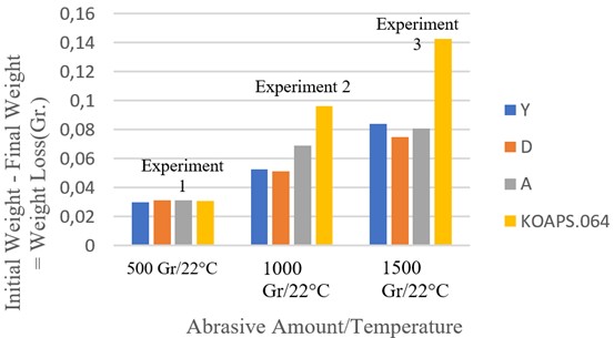
500 grams of abrasive particles were used and it was determined that difference in the erosion rate on the experimental results was not clearly evident in the first experiment applied to samples. Since the sample production method and orientation were expected to reveal a clear difference on the experimental results, 2 more experiments were conducted using 1000 grams and 1500 grams of abrasive particles. When test results were analysed, cast specimens with highest hardness and lowest surface roughness were worn the most. It is believed that here, because of the layered production structure of additive manufacturing, outermost layer acts as a protector against remaining layers inside the structure. Additive manufacturing specimens wear less than cast specimens due to the protection of the outermost layer while the other layers are destroyed during particle impact. Among 3 different orientations, it is suggested that samples produced with vertical orientation wear less than others due to contact between the layers depending on particle impact angle. Since 45° oriented specimens come into contact with the particles both from layer surface and from gap between layers, it is thought that particles hitting between layers force layers to separate and reduce the strength, while particles contacting layer surface disintegrate the layer. Therefore, the angled specimens were worn more than others. Damage mechanism and change in amount of wear are schematically depicted in Fig. 4. Examination of damage surfaces will give an idea about ductile or brittle character of damage.
The schematic in Fig. 4 illustrates effect of orientation on wear results in additive manufacturing part production. During collision of horizontally layered additive manufacturing specimens with solid particles, particles hit layer joints as little as possible. Particles hitting the first layer of horizontal specimens destroy the first layer and reach other layers less. Amount of erosion wear is reduced in horizontally oriented specimens due to fact that first layers of horizontally oriented specimens in contact with particles act as a protector for the inner layers. However, horizontally oriented In718 specimens were not as low as vertically oriented ones. Particle removal from structure is as low as possible in vertical specimens, as particles intensively contact layer joints. Although weakening of layer joints as a result of contact makes amount of wear low, it is also predicted that strength level of the vertical specimens will decrease. The amount of wear in angled specimens was the highest among additive manufacturing specimens due to particles hitting layer surfaces as well as layer joints. While structure is weakened due to particle impact in interlayer regions, it is easier to remove parts from weakened structure due to particles hitting layer surface. Consequently, the amount of wear was higher in angled specimens compared to vertically and horizontally oriented specimens. Since cast specimen did not have any layers in structure, parts were broken off directly from surfaces by collision with particles. For this reason, the amount of wear was higher compared to additively produced In718 samples.
Fig. 4Schematic representation of the change in the amount of wear
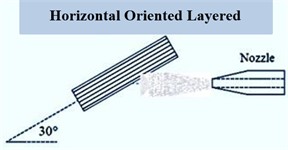
a) Horizontal
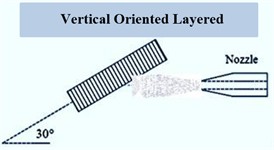
b) Vertical
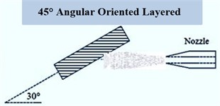
c) Angular
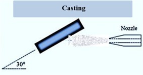
d) Casting
Experiments were conducted at various impact angles with use of 500 gr abrasive particles to determine ductile or brittle behavior of structures in erosion wear. The experiments were carried out at impact angles of 30°, 45°, 60° and 90°, and curves with regression levels of min. 0.97 were fitted to pass through points determined for determination of intermediate values. Thanks to the fitted curves, it was possible to see how wear tends and to predict results depending on the angular variability. The results were interpreted with information found in literature. According to literature, ductile behavior dominates up to an impact angle of 30°, whereas as impact angle increases, there is a phenomenon that brittle behavior dominates. Fig. 5 shows graphs of results obtained for determination of ductile, brittle or semi-ductile behavior.
Fig. 5Amount of erosion wear at different impact angles to determine the behavior
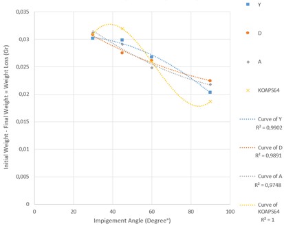
The cast In718 specimens reached a peak at 45° impact angle and then decreased. In the literature, it is said that ductile character will be dominant at 30° impact angle and wear will peak, whereas this situation was realized at 45° impact angle for cast In718 specimens. Therefore, it can be said that ductile behavior is postponed compared to literature. It can be said that fact that material is nickel alloy and In718 alloy exhibits high mechanical properties is effective here. Looking at specimens produced by additive manufacturing, it was observed that amount of wear of horizontally oriented specimens did not change up to 45° impact angle and decreased up to 90° impact angle. It can be said that ductile behavior of horizontally oriented In718 specimens, similar to castings, occurs up to 45° impact angles. It was observed that ductile behavior in vertical specimens occurred at 30° impact angle and as impact angle increased, wear decreased and behavior turned to brittle character. Angled specimens responded similarly to horizontally oriented specimens. In general, when compared with studies in literature, it is confirmed that brittle behavior becomes dominant as impact angle increases. However, the hypothesis that ductile behavior becomes dominant and wear peaks at 30° impact angle was postponed in experiments for In718 alloys and was observed to occur later. Ductile behavior occurred at 45° particle impact angle. Difference in ductile behavior with literature is thought to be due to fact that the material is In718 alloy. Surface topography and macroscope images provide a more observational interpretation of damage to the surface.
5.1. Surface topography and macroscope images
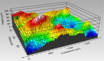
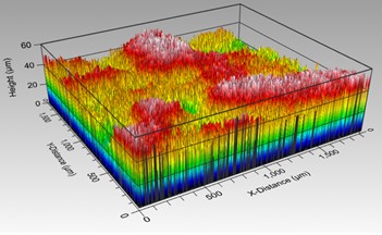
Experiments at an impact angle of 30° were used for determination of damage on surface. Since no trend was observed in experiments using 500 gr. abrasive, the surface topography and macroscope image were taken from the experiments using 1500 gr. abrasive. Topography images are given in Fig. 6.
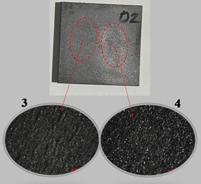
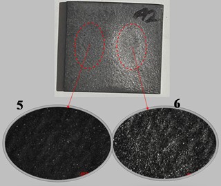
Fig. 6Specimen wear and non-wear zone surface topography images
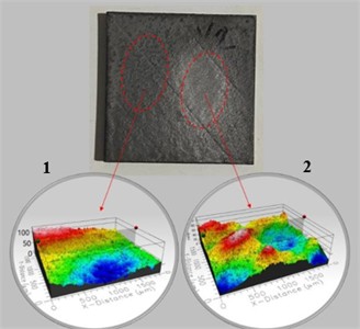
a) Y1 – Y2. 1 – non wear; 2 – wear
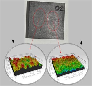
b) D3 – D4. 3 – non wear; 4 – wear
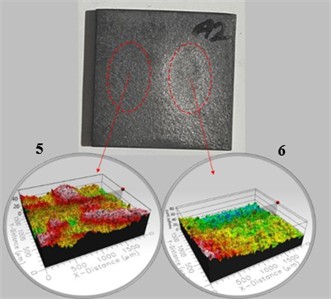
c) A5 – A6. 5 – non wear; 6 – wear
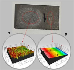
d) KOAPS7 – KOAPS8. 7 – wear; 8 – non wear
When the images in Fig. 6 are examined, the topography images taken from sample surfaces are taken from an area of 2 mm×2 mm. Image acquisition distinguished between wear and non-wear areas. The damage on the surface in experimental group, where most intense amount of erosion was achieved with use of 1500 gr abrasive, is understood from the images. In the cast In718 sample, where most wear occurred, non-wear areas (KOAPS8) have a flat and smooth appearance, while wear sections are highly roughened. Additive manufacturing specimens may be considered rough on all surfaces, including areas not abraded due to their manufacture. However, the wear zones have undergone more intense deformation and amount of roughness has increased. The cross-sectional thickness of worn areas is also reduced. A detailed topography examination was carried out in Fig. 7 to numerically reveal surface topography of the surfaces and the difference between wear and non-wear surfaces.
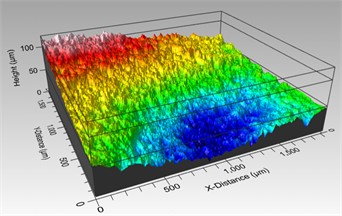
Fig. 7Detailed surface topography image
a) Non-wear Y
e) Wear Y
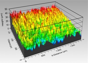
b) Non-wear D
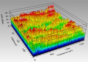
f) Wear D
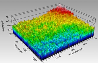
c) Non-wear A
g) Wear A
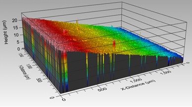
d) Non-wear KOAPS064
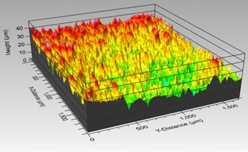
h) Wear KOAPS064
When the topography images of worn and unworn samples are examined in detail, peak in image taken from unworn sections of horizontally oriented additive manufacturing In718 samples appears to be approximately 100 µm. If we accept this as unworn reference sample boundary, lowest point has dropped to approximately 15-20 µm in image taken from a 2 mm×2 mm area from the most intense part of worn area on the horizontal sample. Due to erosion wear, approximately 75-80 µm of surface was lost and section thickness decreased to a maximum of these levels in eroded region. In vertically oriented additive manufacturing samples, an abrasion loss of approximately 30-35 µm occurred from a 50 µm reference surface, decreasing to around 10-15 µm in the deepest region. This situation developed in the same way in angular and casting samples. A wear of approximately 35 µm occurred in the angled samples. There was also an abrasion of around 20 µm in the cast samples, but since this value spread more over surface compared to additive manufacturing samples, it was concluded that weight loss was higher. It can be understood that casting samples are least thinned in terms of sectional examination. In addition, no homogeneous damage occurred on surfaces hit by particles. While surface areas that came into contact with particles collapsed, non-contact areas only increased in roughness. This situation is common in 4 types of samples. These values are written as maximum because areas where image is taken are areas where wear is most intense. surface roughness values are read with help of device used in area where topography measurements are taken. In this context, comparisons can be made with unworn samples in the roughness of the area where the topography was taken, before and after wear. The distinction between wear and non-wear areas can be more clearly distinguished from macroscope images. Fig. 8 shows macroscope images of the samples.
Fig. 8Specimen wear and non-wear zone macroscope image
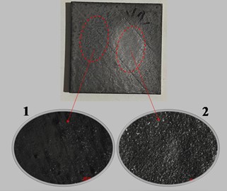
a) Y1 – Y2. 1 – non wear; 2 – wear
b) D3 – D4. 3 – non wear; 4 – wear
c) A5 – A6. 5 – non wear; 6 – wear
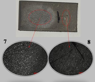
d) KOAPS7 – KOAPS8. 7 – wear; 8 – non wear
The difference between wear areas and non-wear areas can be better understood by looking at macroscope images. While a flat and smooth appearance was not formed in non-wear zones of the In718 samples produced by additive manufacturing other than casting sample due to production method, surface deformation appeared more dominantly in wear areas due to erosion effect. As a result of wear, the unworn area of cast sample had a smoother appearance in proportion to topography image, while a rough surface was formed in worn area due to effect of solid particle erosion. When roughness results obtained with topography image taken from wear zone of the horizontally oriented additive manufacturing samples are examined, Ra value varies between 1 and 1.5. Surface roughness has increased slightly compared to non-wear horizontal additive manufacturing sample in Table 2. The Ra value was measured between 0.9 and 1.4 in the wear area of the vertical samples. However, there is no excessive increase. Among additive manufacturing samples, Ra value on non-wear surface of angled samples and casting In718 samples showing excessive wear was measured at approximately 0.6 and 0.06 levels, while after wear, it climbed to 1 level for angled additive manufacturing and Ra measurement for castings was made at 0.015 levels. As a general result, particles increased roughness of surfaces as a result of erosion, but these measurements are made from a limited area. In this direction, evaluation of entire surface and all worn areas in terms of surface roughness will give more accurate results.
6. Conclusions
Jet engine turbine blades, which are among critical components in aircraft pose a manufacturing challenge. As a result of the difficulties, production of turbine blade structures using additive manufacturing techniques has become a preferred option. Due to environment in which aircraft operates, turbine blades may be exposed to solid particle erosive wear. Damage occurs to structures due to collision effect with hard and micron-sized particles in environment. An investigation was carried out to explain damage in advance and to determine whether a new production technique would be useful in such structures.
As a result of the research, In718 alloys produced by selective laser melting that a layered production technique, were rougher and had lower hardness compared to nickel alloys produced by casting, but weight loss due to erosive wear was less. In addition, when the surfaces, where damage occurred are examined, the difference between the undamaged and worn areas can be clearly observed. When results obtained in terms of wear are evaluated, the fact that component forms produced with additive manufacturing show less wear brings additive manufacturing to forefront. The reason for difference in the amount of wear between additive manufacturing samples is great effect of horizontal, vertical and angled orientation. As can be seen in Fig. 5, horizontal layered additive manufacturing samples reduced amount of wear due to preservation of other layers while sacrificing only first layer during collision with solid particle. However, it showed higher wear compared to vertically oriented additive manufacturing. The fact that vertical samples exhibited least wear was due to fact that dust particles did not lift pieces from surface but accumulated between layers, thus creating less wear, but it is also estimated that mechanical properties of vertical samples decreased. The reason why angled samples show high wear is that strength of structure decreases as pieces are removed from both the interlayer and layer surfaces, and it is deduced from results that it becomes easier to remove pieces from the surface of structure whose strength decreases. In this context, it is revealed that orientation difference in part production with additive manufacturing affects mechanical properties of structure.
Another finding obtained from study is that hypothesis in literature that deformation characteristics at different impact angles highlight ductile behavior at low impact angles, while turning towards brittle behavior with an increase in impact angle, has been relatively confirmed by this study. The maximum wear amount expected at 30° impact angle occurred at 45° impact angles in horizontally oriented additive manufacturing and cast In718 samples. It is estimated that shift in ductile behavior characteristic is due to use of nickel alloy material. Therefore, contrary to expectations, the ductile characteristic can shift to 45° impact angles. The subjects examined in study showed that additive manufacturing can take place in aircraft and that additive manufacturing parameters can affect mechanical properties of produced structures.
References
-
H. Vasudev, L. Thakur, H. Singh, and A. Bansal, “Effect of addition of Al2O3 on the high-temperature solid particle erosion behaviour of HVOF sprayed Inconel-718 coatings,” Materials Today Communications, Vol. 30, p. 103017, Mar. 2022, https://doi.org/10.1016/j.mtcomm.2021.103017
-
G. Taillon and K. Miyagawa, “Cavitation erosion of Ni-based superalloys manufactured by forging and additive manufacturing,” Journal of Failure Analysis and Prevention, Vol. 21, No. 5, pp. 1902–1917, Oct. 2021, https://doi.org/10.1007/s11668-021-01241-4
-
A. H. Alami et al., “Additive manufacturing in the aerospace and automotive industries: recent trends and role in achieving sustainable development goals,” Ain Shams Engineering Journal, Vol. 14, No. 11, p. 102516, Nov. 2023, https://doi.org/10.1016/j.asej.2023.102516
-
D. A. Pandya, B. H. Dennis, and R. D. Russell, “A computational fluid dynamics based artificial neural network model to predict solid particle erosion,” Wear, Vol. 378-379, pp. 198–210, May 2017, https://doi.org/10.1016/j.wear.2017.02.028
-
B. Bircan, S. Fidan, and H. Çimenoğlu, “Solid particle erosion behavior of Inconel 718 super alloys under elevated temperatures,” Journal of Achievements in Materials and Manufacturing Engineering, Vol. 66, No. 1, pp. 5–12, 2014.
-
M. Kazasidis et al., “Microstructure and cavitation erosion performance of nickel-Inconel 718 composite coatings produced with cold spray,” Surface and Coatings Technology, Vol. 382, p. 125195, Jan. 2020, https://doi.org/10.1016/j.surfcoat.2019.125195
-
A. Kotarska, T. Poloczek, and D. Janicki, “Characterization of the structure, mechanical properties and erosive resistance of the laser cladded Inconel 625-based coatings reinforced by TiC particles,” Materials, Vol. 14, No. 9, p. 2225, Apr. 2021, https://doi.org/10.3390/ma14092225
-
N. Kamboj, L. T. Thakur, and Manpreet Kaur Arora, “The solid particle erosion performance of tungsten inert gas yttria-stabilized zirconia – Inconel 625 composite cladding,” Journal of Electrochemical Science and Engineering, Mar. 2024, https://doi.org/10.5599/jese.2140
-
D. Verdi, R. Cortés, G. Y. Chia, and G. Tay, “Erosion behaviour of laser cladded Inconel 625 – Vanadium carbide metal matrix composites coatings manufactured with different reinforcement contents,” Surface and Coatings Technology, Vol. 476, p. 130282, Jan. 2024, https://doi.org/10.1016/j.surfcoat.2023.130282
-
J.-R. Zhao, F.-Y. Hung, and T.-S. Lui, “Erosion resistance and particle erosion-induced tensile embrittlement of 3D-selective laser melting Inconel 718 superalloy,” Metals, Vol. 10, No. 1, p. 21, Dec. 2019, https://doi.org/10.3390/met10010021
-
C. S. Ramesh, D. S. Devaraj, R. Keshavamurthy, and B. R. Sridhar, “Slurry erosive wear behaviour of thermally sprayed Inconel-718 coatings by APS process,” Wear, Vol. 271, No. 9-10, pp. 1365–1371, Jul. 2011, https://doi.org/10.1016/j.wear.2011.01.057
-
M. Kaplan, M. Uyaner, E. Avcu, Y. Yildiran Avcu, and A. C. Karaoglanli, “Solid particle erosion behavior of thermal barrier coatings produced by atmospheric plasma spray technique,” Mechanics of Advanced Materials and Structures, Vol. 26, No. 19, pp. 1606–1612, Oct. 2019, https://doi.org/10.1080/15376494.2018.1444221
-
B. V. Padmini, D. G. Bhosale, and H. B. Niranjan, “A study of T11 boiler steel protection by cold sprayed Inconel 738 coating against high temperature erosion,” Surfaces and Interfaces, Vol. 23, p. 101002, Apr. 2021, https://doi.org/10.1016/j.surfin.2021.101002
-
C. S. Ramesh, R. S. Kumar, M. Murthy, and Harsha, “Slurry erosive wear behaviour of copper plasma sprayed with titania-30wt% Inconel 718,” Procedia Materials Science, Vol. 5, pp. 1130–1135, Jan. 2014, https://doi.org/10.1016/j.mspro.2014.07.407
-
K. G. Thirugnanasambantham, A. Francis, R. Ramesh, A. M., and M. K. Reddy, “Investigation of erosion mechanisms on IN-718 based turbine blades under water jet conditions,” International Journal on Interactive Design and Manufacturing (IJIDeM), pp. 1–6, May 2022, https://doi.org/10.1007/s12008-022-00910-4
-
V. K. Dwivedi, P. Sharma, and D. Kumar, “Modeling and multi-objective optimization for APSed thermal barrier coatings on IN718,” Surface Review and Letters, Vol. 28, No. 6, p. 2150040, Mar. 2021, https://doi.org/10.1142/s0218625x21500402
-
K. G. Thirugnanasambantham and S. Natarajan, “Degradation through erosion: mechanistic studies on IN-718 superalloy under hot air jet conditions,” Journal of Materials Engineering and Performance, Vol. 24, No. 7, pp. 2605–2613, May 2015, https://doi.org/10.1007/s11665-015-1538-6
-
Z. Zhang et al., “Cold spray deposition of Inconel 718 in comparison with atmospheric plasma spray deposition,” Applied Surface Science, Vol. 535, p. 147704, Jan. 2021, https://doi.org/10.1016/j.apsusc.2020.147704
-
J. Alqallaf, N. Ali, J. A. Teixeira, and A. Addali, “Solid particle erosion behaviour and protective coatings for gas turbine compressor blades-a review,” Processes, Vol. 8, No. 8, p. 984, Aug. 2020, https://doi.org/10.3390/pr8080984
-
V. Bonu and H. C. Barshilia, “High-temperature solid particle erosion of aerospace components: its mitigation using advanced nanostructured coating technologies,” Coatings, Vol. 12, No. 12, p. 1979, Dec. 2022, https://doi.org/10.3390/coatings12121979
-
M. Kaplan, “A study of erosion wear behavior of Inconel-718 nickel-based superalloy at different impingement angles,” Uğur Köklü, Vol. 2, No. 2, Oct. 2023, https://doi.org/10.5281/zenodo.10014151
-
M. Demirci and M. Bagci, “Alternative system design for high temperature solid particle erosion wear problem,” Tribology Letters, Vol. 69, No. 1, pp. 1–11, Jan. 2021, https://doi.org/10.1007/s11249-021-01400-6
About this article

This research was completed with the support of Konya Technical University Scientific Research Coordination Office.
The datasets generated during and/or analyzed during the current study are available from the corresponding author on reasonable request.
Mehmet Esat Aydın: writing-original draft preparation, conceptualization, investigation. Musa Demirci: data curation, resources, visualization. Mehmet Bağcı: writing-review and editing, project administration
The authors declare that they have no conflict of interest.
