Abstract
The article discusses the fundamental dependencies and provides an example of a new type of signal converter for physical quantities that are related in the tested object. The review consolidates a relatively niche but critical area: dual-source bridge circuits, which are often scattered across instrumentation and sensor literature. Three key objectives are as follows: to systematically review dual-source bridge circuits used as signal converters, particularly in the context of sensors that measure interrelated physical quantities (e.g., strain and temperature); to analyze existing circuit topologies and conversion principles used in such systems; and to assess the applicability, limitations, and performance of various bridge configurations across different sensor applications. Performance metrics like sensitivity, linearity, and temperature compensation are often superior in dual-source setups when compared to single-source designs. Signal processing and calibration complexity can be reduced at the hardware level using these bridge configurations. Several circuit implementations offer trade-offs between complexity, power consumption, and accuracy. The literature review and bibliographic data on dual-source circuits, experimental studies, and prototype designs of dual-current DC bridges as prototype transducers of signals of associated quantities and their application are included. Further functions of these circuits in future systems are outlined.
Highlights
- Dual-source bridge circuits used as signal converters, particularly in the context of sensors that measure interrelated physical quantities, such as strain and temperature, were presented.
- Existing circuit topologies and conversion principles used in such systems were reported to assess the applicability, limitations, and performance of various bridge configurations across different sensor applications.
- The literature review was supported by bibliographic data on dual-source circuits, experimental studies, and prototype designs of dual-current DC bridges and their applications.
1. Introduction
Information about the condition of an object is obtained in the form of signals from both direct studies of its mathematical model parameters and indirect signals obtained through the use of sensors [1-2]. This information is used for monitoring, testing, measurement control, and automation. The values of these parameters must be numerically determined by taking into account their determined and random connections with one another, as well as the changes that result from their interaction with external quantities. Usually, these quantities have a non-selective influence on the signals that are measured [3]. It is only possible to get a signal regarding the influence of one quantity on the others stabilized in limited situations, such as laboratory tests. Usually, signals depend on several interrelated parameters of the observed object [4].
When using sensors, the signals they generate are influenced by a variety of influencing quantities, such as ambient temperature [5]. An example of this is the strain gauge measurement. The change in resistance of a strain gauge is influenced by both its deformation and its ambient temperature. An additional temperature sensor or the same non-deformable strain gauge can be used to test or compensate for the impact of changes in the output signal from the temperature of its surroundings [6-7]. Thus, the effect it has on the signal can be compensated in either the analog or digital part of the data acquisition system. If the strain gauge experiences self-heating due to excessive current flowing through it, an attempt to increase sensitivity may result in additional error in the signal.
However, this undesirable effect of temperature changes on the strain gauge resistance can also be used to measure the actual temperature of the transducer and to correct its influence on the output signal. Such a possibility occurs, for example, when using a differential sensor with two identical strain gauges - compressed and stretched [8]. If the resistance changes in strain gauges due to changes in deformation as a result of the measured force or its moment are of different signs, and if the resistance changes associated with temperature change are of the same sign, it is feasible to measure both quantities simultaneously. To achieve this purpose, two output signals should be created in the measuring system, i.e., one for the difference of the resistance changes of sensors and another for the sum. The first one, the basic one, depends on strain gauge deformations, and the second one, an auxiliary one, depends on changes in the sensor temperature. This second signal can also be used to correct the effect of temperature change on the initial value of sensor resistances and the strain gauge differential sensor’s sensitivity coefficient [9].
The first author, Z. L. Warsza, proposed the two-output unconventional bridge circuits fed with two current sources [10-12] and then with two voltage sources [13]. These circuits enable the development of transducers and systems that conduct the simultaneous measurement of two changing parameters. It was suggested to name them dual-source bridges. They constitute a unique type of circuit system that has not been previously described in the literature. In addition, the author has created theoretical foundations for balanced and biased dual-source bridges for direct current (DC) and alternating current (AC), principles of estimating their signals and accuracy, and examples of applications. They are discussed in numerous works, such as the monograph [13]. The circuits were also suggested to have names and symbols: dual-current bridge (2J) and dual-voltage bridge (2E), with two outputs: open circuit voltage (2U) or short circuit current (2I).
In balanced dual-source bridge circuits, the sources should be the same, or the output signal values should be averaged when switching sources. If these signals are not coming from balanced outputs, these sources must also have known and stable values. With direct current sourcing, two output signals can be obtained simultaneously as a function of bridge immittances, i.e., resistances or conductances, or the sums and differences of their changes from the equilibrium states of the outputs [14]. The AC dual-source bridge circuits can be used to measure the components of two impedances and their changes. There are several examples of such applications given in [13].
Most existing literature focuses on single-source Wheatstone bridges. There is a limited side-by-side comparison of single-source vs. dual-source performance in terms of sensitivity, linearity, noise immunity, and power consumption. There is insufficient analysis of error sources in dual-source configurations. Dual-source bridges are less common in integrated sensor systems or ASIC designs. Based on these research gaps, the motivations for reviewing dual-source bridge circuits include:
– Enhancing linearity and range: Dual sources allow dynamic balancing or compensation, which improves linearity and sensitivity for sensors with nonlinear characteristics.
– Improving signal-to-noise ratio: By using two sources with opposite-phase or differential characteristics, dual-source bridges can better reject noise and common-mode interference.
– Support for advanced sensing technologies: Many modern sensors (e.g., strain gauges, MEMS piezoresistive, and bioelectric sensors) require differential or bidirectional excitation.
– Energy efficiency and adaptive excitation: Systems using dual-source bridges can implement smart excitation (e.g., pulsed or modulated sources), which enables energy-saving strategies, especially in battery-operated or remote devices.
– New functional capabilities: Dual-source bridges can enable novel functionalities, such as real-time calibration, self-diagnostics, and multi-sensor interfacing, which are not feasible in conventional single-source bridges.
The analysis of simultaneous measurements of quantities associated with dual-source bridges requires providing basic relations that describe both types of their operation. An example of measuring two quantities (stress and temperature) with a differential strain sensor in both types of dual-source bridges will be presented. The current state of experimental research in this field and recommendations for future research directions will also be addressed. Publications in this field, including some in Polish, are listed in the bibliography.
2. The dual-current resistive bridge circuit and its basic relationships
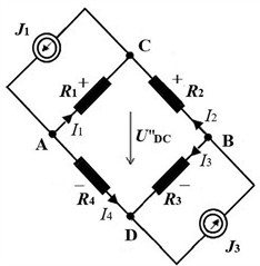
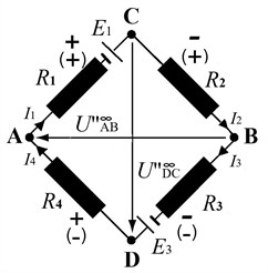
Fig. 1 presents two circuits in the form of a loop with resistances ... and differently connected current sources. With a single DC source, e.g., current connected to the terminals AB (Fig. 1(a)), a classic Wheatstone bridge with output CD is obtained; this circuit is provided for comparison. The second circuit consists of two DC sources, and , connected in parallel to the opposite terminals, e.g., AC and BD, in the direction of cooperation. There are two different variants, (b) and (c), of signs of voltage imbalance at the outputs from the dual-current circuit’s terminals AB and DC. Classical and multi-source bridge circuits differ not only in the number of power sources but also in the manner in which they are connected and the number of outputs.
Fig. 1Current supplied resistance bridge-circuits; the sign + or – means a resistance change (increment or decrement)
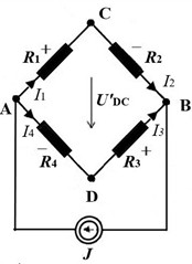
a) Conventional 4R bridge supplied by current via terminals AB and with output DC;
b) Dual-current bridge-circuit supplied by two sources parallel to AC and BD terminals with 2 outputs: DC and AB, ,
c) Dual-current bridge-circuit supplied by two sources parallel to AC and BD terminals with 2 outputs: DC and AB, ,
The dual-current circuit, shown in Fig. 1(b) and Fig. 1(c), has two DC sources and connected sideways (parallel to the opposite branches of the 4R system, e.g., , or , ) in the direction when their currents cooperate. This bridge circuit provides two voltage outputs, AB and DC. According to the theory of linear electric circuits, the passive four-terminal network has an equivalent circuit with six impedances in the form of a quadrilateral with diagonals [13]. It can be considered as a simplified two-port network, with two inputs and two outputs. The full formalized matrix description of such a system is too complicated to use for an unloaded passive four-terminal network. For further consideration, the formulas for two output voltages on both terminals AB and CD of this system are sufficient. For unequal currents , the following output voltages of the dual-current bridge are obtained [13]:
Or:
where .
For two identical current sources the formulas are simplified, i.e.:
For two sources with different current values , the same formulas are obtained by averaging the readings when switching these sources, and even when only one source is used. From Eqs. (5) and (6) for 0 or 0 two equilibrium conditions result directly:
Both pairs of resistance products Eqs. (7) and (8) can have different values. Every output of the dual-current bridge can meet the balance condition, which means that the products of other resistance pairs must be equal. This represents the equality of the products of the resistances adjacent to the terminals of a specific output. For the AB output of the 2J bridge circuit from Fig. 1(b) and Fig. 1(c), this concerns vertical resistances. For the DC output, this concerns the horizontal resistances. The same relations Eqs. (7) and (8) are observed when terminals AD and CB are linked to two equal current sources. To obtain the output balance, two resistance values can be adjusted twice. Two other resistances can be identified.
These conditions are not dependent on the resistance of the leads of the current sources or the same changes in the currents of both sources. For two current sources that are laterally connected to the terminals CB and DA, the same pair of equilibrium conditions will be obtained. The Eqs. (5) and (6) for the output voltages of the dual-current bridge have a similar form to the classic bridge circuit supplied by current (Fig. 1(a)). It is commonly known that in the classic bridge there is equality of the products of resistances of the opposite arms, i.e., and the output voltage is:
A dual-current bridge circuit can also be used as an unbalanced circuit. The circuit resistances can be generally presented as , for 1, 2, 3, 4. If the initial values of satisfy the equilibrium conditions Eqs. (7), (8), then the output voltages appear for resistance changes 0:
When the products of relative changes are very small, i.e.: ( or ) for , they are negligible and the formulas Eqs. (10), (11) are simplified, i.e.:
Based on the existing formulas, it appears that in balanced systems, it is sufficient for the source currents to only be common and identical. In biased systems, the sources should be identical and have a constant known value. In both cases, the results can be averaged after switching the sources.
For an antisymmetric 2 bridge circuit, i.e., with identical impedances in opposite arms for Eqs. (7) and (8), the balance of both outputs occurs simultaneously. An unbalanced dual-current bridge can be used for simultaneous two-parameter measurements using both of its output signals. However, it cannot have loaded outputs because the resistances in the diagonals of the unbalanced system affect the flow of currents. Therefore, the formulas for the output voltages become complicated. Output resistances of an unloaded dual-current bridge circuit are:
Eqs. (14) and (15) are valid for each of the outputs as long as the circuits of both of their voltage outputs are open, meaning they are unloaded or in the balance of two outputs. Moreover, the equilibrium conditions with non-ideal current sources, their internal resistances shunt the parallel resistances of bridge arms, like and in Fig. 1(b) and 1(c), which changes the balance. Then, the resistance values of these parallel connections must be added to Eqs. (1)-(4) [13]. This results in the conclusion that a system that is powered by forced currents and unloaded at the outputs should be employed when both outputs are used simultaneously. The formulas for the output voltages of an unbalanced classic 4 bridge powered by a current source and for the outputs from the diagonals of a dual-current bridge with identical sources have the same form, and the resistances only change placement.
The publications [10-27] listed in the bibliography provide theoretical analysis and descriptions of the results of experiments on two-current bridges.
3. Resistive bridge circuits with two voltage sources – basic formulas
The general properties of electrical systems indicate that there is a dual system for each passive system. Specifically, variants of the dual-current bridge correspond to bridge systems with two voltage sources, which are designated as dual-voltage bridges.
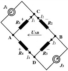
Fig. 2 illustrates the measuring circuit of the dual-voltage bridge 2E2U, which operates with two DC voltage sources, and , and two unloaded outputs , (AB and DC). This system has not been included in the literature on measurement systems, despite being fairly straightforward to implement. The closest approach is an electrical circuit as a single cell for comparing two voltages or two resistances. Krawczyk et al. [28] implemented a voltage bridge, which is a different circuit that utilizes two DC voltage sources to transmit high resistance standards.
Additionally, the author employed the same circuit structure for comparing two simultaneously induced voltage pulses during coil rotation in two magnetic fields to calibrate Hall-effect meters in a magnetic field with large, insufficiently uniform magnetic inductions that were not measurable with NMR meters.
The implementation of two identical voltage sources is simpler than current sources that operate with alternating current (AC). In this case, it is possible to use a common source and a transformer or an inductive divider with two identical secondary windings.
The output voltages of the dual voltage bridge circuit in Fig. 2 are:
Fig. 2Dual-voltage bridge circuit supplied by two voltage sources E1, E3
When = 0 or = 0, two different balance conditions are obtained:
The outputs of this circuit can be balanced by adjusting the values of the source voltages and in a manner that is similar to the voltage bridge in [28]. Additionally, resistances can be employed. If the source voltages in the opposing branches of the 22 circuit are equivalent, i.e., , or if an average result of two measurements is obtained by swapping the sources, the unloaded voltages of the and outputs are as follows:
And for the balance conditions Eqs. (18), (19) will be as follows:
Therefore, the formulas of dual-voltage bridges are simpler than those of classic and dual-current bridges.
The bridge resistances can be written in general as . If their initial values satisfy the equilibrium condition Eqs. (18) or (19), then the output voltages of that circuit for resistance changes 0 are:
Consequently, the bridge circuits depicted in Fig. 2 can be used to quantify two linear combinations of resistance changes from their equilibrium values, where the source voltages are constant and identical ().
Other circuits that are connected to both outputs of the bridge circuits from Fig. 1(b), Fig. 1(c), and Fig. 2 should have an input resistance that is appropriately higher than the output resistances of the bridge circuits. When dual-voltage outputs are unloaded (open circuits), the output resistance formulas are identical to Eqs. (14) and (15). This information can be used in resistance tests between the terminals of equivalent circuits of objects with an inseparable structure.
The output signals of dual-source systems from Fig. 1(b), Fig. 1(c), and Fig. 2 can also be short-circuit currents (bridges: 2J2J and 2E2J) [13]. For conductivity equations, they will have comparable forms. They could also be used to measure two quantities, such as the changes in conductance of bridge arms. Active current transducers with parallel feedback should be used at their outputs to ensure that the input resistances have almost no effect. However, in such measuring systems, the influence of lead resistance on the results will still be present.
4. Signals of dual-source bridge circuits for two related resistances and their changes
4.1. Indirect measurements of two quantities (2D) with differential sensors
Nonlinear and linear functions are employed to describe the simultaneous effects of multiple quantities on the parameters of the object, whether measured directly or through sensors. Typically, signals that are independent and influenced by multiple variables are acquired and processed in accordance with specific algorithms.
To more closely examine this matter, we will examine the measurement principle in a straightforward scenario in which each of the small changes and of the measured parameters has such two components, each of which is solely dependent on one influencing quantity or , then:
There are four different components on the right side of the system of equations. When these components are linked to two other established relationships, it will be feasible to identify and . For example, it is when these dependencies are linear, i.e.:
and the expanded forms of the components are as follows:
The inverse of a matrix Eq. (28) transformation is as follows:
The partial changes and of the components can be both linear and nonlinear functions of the changes and of the measured quantities. In the system of Eqs. (26, 27) for relative changes, the linear dependencies of changes in the system parameters from the influencing quantities (addition, subtraction with different coefficients) and some nonlinear dependencies are described by varying the coefficients . This is because the sum of small relative changes of several quantities reflects the multiplication of these quantities, and the difference reflects their division.
Consider a differential sensor with two identical elements. In this case, the quantity has the same effect on both of their changes, and , and the influences of the quantity are of the same value but of the opposite sign. Specifically, +1, –1, and:
For each of the aforementioned sensor operations, the changes and can be determined from their components and . Subsequently, the changes and of both quantities can be found.
A variety of measuring, differential, and summing systems can reproduce the measured quantities based on the previously discussed relationships and produce output signals from the changes of two or more parameters based on the dependencies mentioned above. Resistive sensors and object models offer various options for measuring resistance changes. For example, resistive sensors can be connected in series with a constant reference resistance and supplied with a stabilized current source. All subsequent voltage drops can be digitally measured with high precision, stored, and subsequently processed as necessary. To get a single result with only two variable resistances, at least six measurements are required, including three for the initial state. The number of measurements and processing steps rises with each additional resistance. Despite being automated, this method is not a convenient option, particularly when values are rapidly changing. It is only appropriate for use in laboratory conditions.
If the result depends on a very small difference between the two voltages that were measured, it might be inaccurate. Errors cannot be continuously and easily eliminated. In these situations, single-parameter classic bridges still have some known advantages over measuring both voltages directly. For example, they have a very high zero stability due to the stability of their passive components. Bridge circuits generate signals that are linearly dependent on the sum or difference of small changes in relative resistance. They are frequently employed as inputs to industrial transducers or computer measurement systems. Bridge output signal nonlinearities arise for larger changes in immittance, but they can be removed by digital signal processing correction, feedback, or bridge element selection.
Classical deflection bridges are single-output and have a single output signal. The dual-source DC bridges that have been proposed produce two output signals that are simultaneously and independently influenced by the resistance changes of the bridge arms from their equilibrium values.
4.2. Relationships for measuring stress and temperature using a differential sensor
In sensors of force or pressure, 2 or 4 identical strain gauges are placed on the structure that is subject to deformation. One or two two-element differential sensors are involved. The tension is applied to one pair of strain gauges, while compression is applied to the other. However, the resistance changes of this pair of strain gauges exhibit opposite signs, despite their similar values. Additionally, the resistances of the strain gauges are contingent upon their temperature, which is a consequence of the ambient temperature and the self-heating of the current that passes through them. It can be presumed that the nominal initial resistances of both strain gauges and their sensitivity to temperature changes and deformation are identical for such a differential sensor.
The bridge is balanced if the differential sensor components are positioned in the adjacent arms, e.g., 1 and 2, of the discussed dual-source bridge, at a specific reference temperature , and for an initial value of the measured stress , e.g., equal to zero. Then, at the outputs are signals that represent the difference between changes and their sum. The resistances of the pair of strain gauges are:
where are their changes: ; .
For a dual-current bridge 2J2U, with identical resistances , from Eqs. (10) and (11) it follows:
Terms that are product of small resistance changes are omitted in the approximations.
For a dual-voltage bridge with the symbol 2E2U, when , from Eqs. (16) and (17) we obtain respectively:
These formulas are simple and similar to Eqs. (12), (13) for small resistance changes in a dual-current bridge (2J2U).
Two voltage sources in a dual-voltage bridge circuit do not have a common terminal. Therefore, if they are implemented electronically, their DC supply circuits should be isolated from one another. The utilization of two identical secondary windings in a voltage transformer or an inductive divider, as well as a primary winding that is stabilized to function as a deflection bridge, is a more efficient method of accomplishing this with alternating current (AC).
4.3. The state of the art and proposed direction of research on dual-source bridges
A dual-source bridge that measures two quantities at once is a new type of measurement circuit. In 2000, the first author of this article introduced the concept of dual-current bridges in Polish, initially referring to them as anti-bridges [10]. In the following years, he wrote about them in other publications, including the first ones in English [11, 12]. Their theoretical foundations were fully developed in his monograph [13], which came out in 2004. In this book, there are several variants of dual-source bridges that include direct current (DC) and alternating current (AC) circuits, a cascade bridge (bridge in a bridge) [19], and examples of bridges with two voltage sources. The bibliographic data on the dual-current DC bridge circuits (known as double-current bridges or two-current-source supplied circuits) is presented in Table 1. This was done by searching for keyword combinations in two databases.
Table 1The bibliographic data on the dual-current DC bridge circuits
Number of items | Number of citations | Time span | |
Scopus database | 19 | 66 (22) | 2002-2019 |
Web of science database | 20 | 61 (39) | 2005-2017 |
Earlier experimental work, specifically studies of changes in the parameters of the equivalent circuit of four-terminal Hall sensors (4T), gave rise to the concept of this new type of bridge. The reversible part of this schematic is a complete quadrilateral with intersecting diagonals and resistances of six branches that vary based on the Hall effect sensor’s temperature and measured magnetic induction B. The author found that the structure of a flat 4T circuit was equivalent to a quadrilateral. As a result, he developed and experimentally tested new systems for temperature-independent compensation of the initial voltage asymmetry at magnetic induction 0 of the Hall effect sensor. This voltage depends only on the sensor current. A dual-current-powered system with a Hall effect sensor, with its output connected to a resistive bridge, was also proposed by Warsza. An adjustable nonlinear output voltage is produced in this circuit as a function of magnetic induction B.
After several theoretical publications [10-13], [15], [19] by the first author, Z. L. Warsza, the second author, A. Idzkowski, became interested in experimentally developing a new type of measuring bridge circuit. As part of his work for PhD research at Bialystok University of Technology, he constructed, tested, and verified dual-current DC bridge systems. Then he, in collaboration with J. Makal and also with Z. L. Warsza consultations, investigated the utilization of a dual-current bridge 2J2U for the measurement of two interrelated parameters [16-18]. Additionally, this bridge circuit was implemented in a laboratory stand to quantify deflection and temperature of a metallic beam, utilizing only two strain gauges and no temperature sensor. Subsequently, A. Idzkowski and W. Walendziuk and their collaborators constructed, tested, and described numerous instrumentation models (2J2U, 2x1J2U, 2J+2R2U) by employing a dual-current DC bridge concept. Publications [23-27] contain these investigations and the models they constructed. They also submitted two Polish patents. Z. L. Warsza reviewed and verified the majority of the aforementioned works. The common features and differences of the analyzed dual-current DC bridge circuits are presented in Table 2. The selected topics and their corresponding publications are provided in Table 3.
Table 2The common features and differences of the analyzed dual-current bridge circuits (DC)
2J2U [13, 22] | 2×1J2U [23, 24] | 2J+2R2U [25, 26] | |
Number of measured parameters | 2 | 2 | 2 |
Number of current sources | 2 | 1 | 2 |
Number of sensors in the system | 2 or 4 | 2 or 4 | 2 or 4 |
The necessity of galvanic separation of sources | yes | no | no |
Sensitivity to difference of current sources | yes | no | yes |
Operation mode | Continuous | Switched | Continuous |
Type of inputs for the bridge signal conditioning circuits | Symmetric | Asymmetric | Symmetric |
The theoretical foundations of dual-source DC and AC bridges, as outlined in the Warsza monograph [13], have been empirically validated through laboratory experiments and a limited number of models. But until now, only electronic measuring systems that make use of dual-current source DC bridges have been verified.
Table 3Dual-current bridge circuits (DC) – the selected topics and their corresponding publications
Topics | Publications |
Sensitivity and nonlinearity | [11], [12], [13], [26] |
Noise performance | [24] |
Accuracy | [13], [21], [22], [25] |
Calibration | [27] |
Measurement applications | [16], [18], [23] |
There was a certain difficulty in this design due to the lack of a common ground between current sources. Commercially available integrated current sources have only been used so far in prototype designs. Two isolated power supply circuits should be used in future professional designs for active systems that generate dual current or voltage sources. The output voltages of dual-source bridges should be measured without loading the outputs. This can be achieved by utilizing differential circuits with operational amplifiers with floating inputs, which are similar to the ones used in the current loop of numerous sensors used by K. F. Anderson [32]. The output voltages can be further processed, either analog or digital, as necessary, depending on the algorithms. In an additional effort to investigate the feasibility of employing the single-voltage power supply with shape potentials in the system, resistances were connected in series with current sources. However, highly stable results were not achieved.
Since the presentation of proposals and after the theory and discussion of numerous AC circuit examples in the monograph [13], the dual-current and dual-voltage AC bridge circuits have not yet been experimentally verified. There is, however, some very close proof of the balanced DC dual-voltage bridge circuits in high-resistance standards comparison [33-35], but they only have one output. Compared to dual-current AC sources, their implementation with AC sources appears to be simpler. For example, a voltage transformer or an inductive divider with two identical secondary windings, which are connected to a single stable AC voltage source, may be implemented for this purpose. The sampling-based digital impedance bridge with a two-output multiplexer for voltage ratio measurement [36, 37] is also a new and interesting idea.
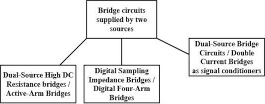
Presently, more research is being done to develop digital bridges (sampling bridges, four-arm bridges) that replicate the behavior of classical analog bridges but with automation, self-balance, and lower cost. This research focuses on comparing impedance standards and enhancing impedance measurement accuracy. As presented in Fig. 3, the literature contains three bridge circuit variants that are supplied by two sources.
– Dual-Source High DC Resistance Bridges [34, 35], also known as Active-Arm Bridges [28], employ two voltage sources, frequently DC, in the active arms of a bridge. This idea is used for the resistance standard calibration system with the use of high-resistance transfer standards in the range of 10 GΩ to 100 TΩ.
– Digital (sampling) impedance bridges [36], [38], [39], [41], also known as digital four-arm bridges [40] for the comparison of resistance with capacitance (impedance standards), they employ a two-channel digital source of voltage sinusoidal waveforms supplying the bridge arms [42-43].
– Unconventional Dual-Source Bridge Circuits, also known as Two-Current-Source Supplied Bridges or Double Current Bridges, are signal converters with two current sources connected in parallel (or to opposing arms) so that each helps excite a different section of the bridge. This may enable a simultaneous measurement of more than one variable.
Fig. 3Variants of bridge circuits that are supplied by two sources
Research into the properties of unconventional dual-source bridges remains a proposal for a new direction of theoretical and experimental research in the field of new solutions for autonomous instruments and input circuits with sensors for monitoring, measurement, and automation systems [44, 45].
4.4. Limitations and application areas
The limitations of dual-source bridge circuits are that they require stable excitation voltages if output is measured directly (unless ratiometric). For very low resistance, lead/contact resistance becomes non-negligible. Their strengths are high sensitivity for small resistance changes and good cancellation of common-mode effects (e.g., supply voltage drift). Application areas well covered are strain gauges, load cells, and temperature sensors. The hard-served area is ultra-low-power bridge-based sensing in harsh and constrained environments (e.g., IoT devices, implantables, remote sensors). The problem is how to get good precision with minimal excitation voltage/current, minimal power, and minimal drift.
5. Conclusions
Dual-source bridge circuits are well placed to support the evolution toward smarter, more accurate, and more versatile sensor systems. The primary functions of dual-source bridges in future systems are listed below.
1) Enabling excitation flexibility and improved control is essential when small resistance changes must be measured with high accuracy over a wide range of environmental conditions.
2) To facilitate digitally-assisted compensation, sensor systems can correct for drift, nonlinearity, and temperature effects by utilizing internal intelligence.
3) To aid in the integration of smart sensor ICs/modules, the excitation, bridge, amplifier, ADC, communication, and diagnostics are combined.
4) Allowing for more robust measurement topologies (e.g., dual channels, diagnostics, redundancy), which is crucial in industrial or safety-critical environments.
5) To enable the implementation of innovative measurement methods, such as digital or virtual bridges for impedance measurement, that necessitate multiple excitations.
The integration of dual-source bridge circuits with smart sensors and in-sensor processing seems to be a highly promising direction for modern sensing systems [46-47]. It enables greater precision, autonomy, and energy efficiency, making it ideal for applications in industrial, biomedical, and next-generation Internet of Things sectors [48]. Possible architecture could include sensor elements (e.g., strain gauges) configured in a dual-source bridge and an analog front-end (AFE) within the smart sensor to digitize the differential output. An in-sensor processing unit may carry out temperature compensation, nonlinearity correction, offset/gain calibration, noise filtering, FFT (Fast Fourier Transform), feature extraction, and AI (Artificial Intelligence) inference. Digital output or wireless transmission are viable options for such a system.
The authors encourage anyone else interested in developing such a new technology to pursue this topic, which is both scientifically appealing and implementation-oriented. This may encompass the analysis and description of numerous potential solutions for transducers of associated signals, such as bridge circuits that utilize two sources of alternating current or voltage.
References
-
T. Kosec, V. Kuhar, A. Kranjc, V. Malnarič, B. Belingar, and A. Legat, “Development of an electrical resistance sensor from high strength steel for automotive applications,” Sensors, Vol. 19, No. 8, p. 1956, Apr. 2019, https://doi.org/10.3390/s19081956
-
D. Ramírez-Muñoz, R. García-Gil, S. Soriano-Díaz, S. Cardoso, and P. P. Freitas, “Magnetoresistive shunt as an alternative to wheatstone bridge sensors in electrical current sensing,” Electronics, Vol. 13, No. 15, p. 2991, Jul. 2024, https://doi.org/10.3390/electronics13152991
-
I. Shankhour, J. Mohdad, F. Mailly, and P. Nouet, “Fully electrical post-fabrication trimming of resistive sensors,” Sensors, Vol. 22, No. 3, p. 767, Jan. 2022, https://doi.org/10.3390/s22030767
-
Z. Zhang et al., “A pressure and temperature dual-parameter sensor based on a composite material for electronic wearable devices,” Micromachines, Vol. 14, No. 3, p. 690, Mar. 2023, https://doi.org/10.3390/mi14030690
-
S. Yan et al., “Design and fabrication of full wheatstone-bridge-based angular GMR sensors,” Sensors, Vol. 18, No. 6, p. 1832, Jun. 2018, https://doi.org/10.3390/s18061832
-
C. Gillot et al., “Wireless strain gauge for monitoring bituminous pavements,” Applied Sciences, Vol. 14, No. 6, p. 2245, Mar. 2024, https://doi.org/10.3390/app14062245
-
A. Cazzani, A. Menichino, M. Inverno, and M. Belardo, “Strain gauge thermal compensation: approaches and new improvements,” in 2023 IEEE 10th International Workshop on Metrology for AeroSpace (MetroAeroSpace), pp. 43–48, Jun. 2023, https://doi.org/10.1109/metroaerospace57412.2023.10190050
-
S. Khan et al., “SSVM: an ultra-low-power strain sensing and visualization module for long-term structural health monitoring,” Sensors, Vol. 21, No. 6, p. 2211, Mar. 2021, https://doi.org/10.3390/s21062211
-
D. M. Ştefănescu, Handbook of Force Transducers – Principles and Components. Heidelberg: Springer-Verlag, 2011.
-
Z. Warsza, “Anti-bridges – a new type of impedance measurement circuits,” (in Polish), in Scientific Conference Measurement Systems in Research and in Industry, 2000.
-
Z. L. Warsza, “Bridges supplied by two current sources-new tool for impedance measurements and signal conditioning,” in IMEKO-TC-7 Symposium, 2002.
-
Z. L. Warsza, “Two parameter (2D) measurements in four terminal (4T) impedance bridges as the new tool for signal conditioning,” in 14th International Symposium on New Technologies in Measurement and Instrumentation, 10th Workshop on ADC Modeling and Testing IMEKO TC-4, 2005.
-
Z. L. Warsza, “Immittance four-pole (4T) systems in multiparameter measurements,” (in Polish), Industrial Research Institute of Automation and Measurements PIAP, Warszawa, 2004.
-
A. Idzkowski and Z. Warsza, “Temperature difference measurement with using two RTD sensors as example of evaluating uncertainty of a vector output quantity,” Robotic Systems and Applications, Vol. 1, No. 2, pp. 53–58, Dec. 2021, https://doi.org/10.21595/rsa.2021.22143
-
Z. L. Warsza, “Two parameter (2D) measurements in double-current supply four-terminal resistance circuits,” Metrology and Measurement Systems, Vol. 13, No. 1, pp. 49–65, 2006.
-
A. Idzkowski, J. Makal, and Z. L. Warsza, “Application of double current bridge-circuit for simultaneous measurements of strain and temperature,” in IEEE Instrumentation and Measurement Technology Conference IMTC 2007, May 2007, https://doi.org/10.1109/imtc.2007.379259
-
Z. L. Warsza, A. Idzkowski, and J. Makal, “Experimental verification of the double-current supplied bridge circuit in 2D measurements of strain and temperature,” in 15th IMEKO TC-4 International Symposium on Novelties in electrical measurements and instrumentation, 2007.
-
A. Idzkowski, J. Makal, and Z. L. Warsza, “Simultaneous measurements of two parameters by double current supplied bridge,” Journal of Automation Mobile Robotics and Intelligent Systems, Vol. 6, No. 2, pp. 26–31, 2012.
-
Z. L. Warsza, “<title>Backgrounds of two variable (2D) measurements of resistance increments by bridge cascade circuit</title>,” SPIE Proceedings, Vol. 6347, pp. 63472R–63472R-10, Oct. 2006, https://doi.org/10.1117/12.714768
-
Z. L. Warsza and A. Idzkowski, “Relations of limited errors and uncertainties type B of the bridge as conditioner circuit for sensors of broadly variable resistances,” Przeglad Elektrotechniczny, Vol. 90, No. 12/2014, pp. 83–86, Jan. 2014, https://doi.org/10.12915/pe.2014.12.19
-
Z. L. Warsza and A. Idźkowski, “Uncertainty analysis of the two-output RTD circuits on the example of difference and average temperature measurements,” Advances in Intelligent Systems and Computing, Vol. 934, pp. 435–446, Mar. 2019, https://doi.org/10.1007/978-3-030-15857-6_43
-
Z. Warsza, A. Idzkowski, and W. Walendziuk, “The parameters of unconventional double-current circuit, their accuracy measures and measurement of strain and temperature,” International Journal of Electronics and Telecommunications, Vol. 60, No. 4, pp. 327–330, Dec. 2014, https://doi.org/10.2478/eletel-2014-0043
-
A. Idźkowski, P. Świętochowski, Z. L. Warsza, and W. Walendziuk, “Unconventional double R/U converter for measurement of two quantities by a single differential sensor,” Advances in Intelligent Systems and Computing, Vol. 352, pp. 83–90, Jan. 2015, https://doi.org/10.1007/978-3-319-15835-8_10
-
A. Idzkowski, W. Walendziuk, P. Swietochowski, and Z. Warsza, “Metrological properties of a two-output transducer for measuring sum and difference of small resistances,” Elektronika ir Elektrotechnika, Vol. 23, No. 5, pp. 41–45, Oct. 2017, https://doi.org/10.5755/j01.eie.23.5.19268
-
W. Walendziuk, J. Golebiowski, and A. Idzkowski, “Comparative evaluation of the two current source supplied strain gauge bridge,” Elektronika ir Elektrotechnika, Vol. 22, No. 6, pp. 33–38, Dec. 2016, https://doi.org/10.5755/j01.eie.22.6.17220
-
A. Idzkowski, J. Gołębiowski, and W. Walendziuk, “Analysis and application of two-current-source circuit as a signal conditioner for resistive sensors,” Journal of Electrical Engineering, Vol. 68, No. 3, pp. 200–205, May 2017, https://doi.org/10.1515/jee-2017-0029
-
A. Idźkowski, J. Gołębiowski, and W. Walendziuk, “The calibration process and metrological analysis of a transducer used to measure two physical quantities,” Acta Mechanica et Automatica, Vol. 11, No. 2, pp. 135–142, Jun. 2017, https://doi.org/10.1515/ama-2017-0021
-
K. Krawczyk, M. Lisowski, and M. Kampik, “Active-arm bridge with two-channel dc voltage source for comparison of high-resistance standards in 1:1 ratio,” Energies, Vol. 16, No. 3, p. 1135, Jan. 2023, https://doi.org/10.3390/en16031135
-
A. de Marcellis, C. Reig, and M.-D. Cubells-Beltran, “Current-based measurement technique for high sensitivity detection of resistive bridges with external balancing through control voltages,” IEEE Sensors Journal, Vol. 17, No. 2, pp. 404–411, Jan. 2017, https://doi.org/10.1109/jsen.2016.2627640
-
E. Alnasser, “A novel fully analog null instrument for resistive Wheatstone bridge with a single resistive sensor,” IEEE Sensors Journal, Vol. 18, No. 2, pp. 635–640, Jan. 2018, https://doi.org/10.1109/jsen.2017.2777010
-
P. Różyło, “Failure analysis of beam composite elements subjected to three-point bending using advanced numerical damage models,” Acta Mechanica et Automatica, Vol. 17, No. 1, pp. 133–144, Mar. 2023, https://doi.org/10.2478/ama-2023-0015
-
K. F. Anderson, “The new current loop: an instrumentation and measurement circuit topology,” IEEE Transactions on Instrumentation and Measurement, Vol. 46, No. 5, pp. 1061–1067, Jan. 1997, https://doi.org/10.1109/19.676711
-
G. Rietveld and J. H. N. van der Beek, “Automated high-ohmic resistance bridge with voltage and current null detection,” IEEE Transactions on Instrumentation and Measurement, Vol. 62, No. 6, pp. 1760–1765, Jun. 2013, https://doi.org/10.1109/tim.2013.2250171
-
I. Mihai and F. Galliana, “Application of statistical tools to optimize a dual source electrical high dc resistance bridge,” MAPAN, Vol. 38, No. 3, pp. 573–581, Jun. 2023, https://doi.org/10.1007/s12647-023-00665-7
-
I. Mihai and F. Galliana, “An approach for reliable calibrations of ultra-high value resistors with the dual source bridge,” MAPAN, Vol. 40, No. 2, pp. 547–555, May 2025, https://doi.org/10.1007/s12647-025-00819-9
-
M. Ouameur, R. Vasconcellos, and M. Agazar, “Digital impedance bridge for four-terminal-pair AC resistor calibration up to 20 kHz,” Metrology, Vol. 4, No. 1, pp. 1–14, Jan. 2024, https://doi.org/10.3390/metrology4010001
-
R. Rybski, J. Kaczmarek, and M. Koziol, “A PXI-based calibration system for low-value AC resistors,” IEEE Transactions on Instrumentation and Measurement, Vol. 67, No. 4, pp. 905–911, Apr. 2018, https://doi.org/10.1109/tim.2018.2791298
-
K. Musioł and M. Kampik, “Development of four-terminal pair sampling-based digital impedance bridge,” Metrology and Measurement Systems, Vol. 32, No. 1, pp. 1–9, Apr. 2025, https://doi.org/10.24425/mms.2025.152771
-
M. Kampik et al., “An improved sampling-based impedance bridge,” Energies, Vol. 18, No. 17, p. 4733, Sep. 2025, https://doi.org/10.3390/en18174733
-
Y. Wang and S. Schlamminger, “A digital four-arm bridge for the comparison of resistance with capacitance,” Metrologia, Vol. 61, No. 5, p. 055009, Oct. 2024, https://doi.org/10.1088/1681-7575/ad7590
-
K. Kontorski, R. Rybski, and J. Kaczmarek, “Improving the accuracy of digital unbalanced impedance bridges,” Energies, Vol. 16, No. 9, p. 3833, Apr. 2023, https://doi.org/10.3390/en16093833
-
Y. Wang, D. Jarrett, A. Koffman, and S. Schlamminger, “New method for determining time constant of resistors,” Review of Scientific Instruments, Vol. 94, No. 3, Mar. 2023, https://doi.org/10.1063/5.0143225
-
V. G. Melnyk, A. D. Vasylenko, L. N. Semenycheva, O. V. Slitskiy, O. Y. Saiapina, and S. V. Dzyadevych, “Solutions for enhancement of sensitivity and metrological reliability of conductometric biosensor systems,” Engineering Research Express, Vol. 3, No. 4, p. 045008, Dec. 2021, https://doi.org/10.1088/2631-8695/ac2a0d
-
A. Flammini and A. Depari, “Advanced interfaces for resistive sensors,” in Smart Sensors and MEMs, Elsevier, 2018, https://doi.org/10.1016/b978-0-08-102055-5.00008-5
-
B. Maundy and S. J. G. Gift, “Strain gauge amplifier circuits,” IEEE Transactions on Instrumentation and Measurement, Vol. 62, No. 4, pp. 693–700, Apr. 2013, https://doi.org/10.1109/tim.2013.2246904
-
P. Yadav, “Advancements in machine learning in sensor systems: insights from sensys-ML and TinyML communities,” in 2024 IEEE 3rd Workshop on Machine Learning on Edge in Sensor Systems (SenSys-ML), pp. 21–26, May 2024, https://doi.org/10.1109/sensys-ml62579.2024.00009
-
A. Ronco, L. Schulthess, D. Zehnder, and M. Magno, “Machine learning in-sensors: computation-enabled intelligent sensors for next generation of IoT,” in IEEE Sensors, Oct. 2022, https://doi.org/10.1109/sensors52175.2022.9967240
-
M. Besirli et al., “An energy-efficient bridge-to-digital converter for implantable pressure monitoring systems,” IEEE Transactions on Biomedical Circuits and Systems, Vol. 16, No. 5, pp. 732–741, Oct. 2022, https://doi.org/10.1109/tbcas.2022.3187828
About this article

The authors have not disclosed any funding.
The datasets generated during and/or analyzed during the current study are available from the corresponding author on reasonable request.
Zygmunt L. Warsza contributed the central idea, analyzed most of the data, and wrote the initial draft of the paper. Adam Idzkowski contributed to refining the ideas, carrying out additional analyses, and finalizing this paper.
The authors declare that they have no conflict of interest.
