Abstract
This article presents a modular, reconfigurable robotic system for upper-limb rehabilitation that supports customizable therapy of the wrist, elbow, and shoulder – individually or in coordinated multi-joint modes. Unlike fixed-structure devices, the design features adjustable link lengths and a symmetric architecture that accommodates both left and right limbs and a wide range of patient anatomies. The current paper develops complete kinematic and dynamic models that include nonlinear inertial, Coriolis, and gravitational effects and integrates these models with real-time torque- and force-control strategies to achieve precise, safe motion tracking. The modular hardware and control stack facilitate instantaneous reconfiguration of the workspace, impedance, and safety limits to align with patient-specific protocols and progression. This research paper simulates the approach in detailed numerical modeling that demonstrates the robot’s kinematic reachability, dynamic controllability, and the effectiveness of fault-tolerant reconfiguration strategies under representative disturbance scenarios. Finally, the current analyses discuss practical considerations for implementation, friction and contact modeling – and outline how the system can accelerate translation for clinical trials. This work mathematically provides a practical, model-based platform for patient-tailored rehabilitation robotics and a foundation for further research in adaptive control and assistive therapy technologies.
Highlights
- Modular Reconfigurability
- Universal Symmetric Design
- Sophisticated 15-Link Architecture
- Comprehensive Nonlinear Modeling
- Multi-Mode Training and Stability
1. Introduction
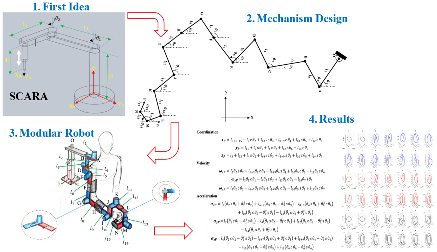
Upper limb rehabilitation robots are special medical machines that help patients regain movement in their arms, hands, and shoulders after injuries like strokes or other conditions that affect movement. These robotic systems work by guiding patients through repetitive, controlled movements that help retrain the nervous system and rebuild muscle strength and coordination. The robots can operate in various modes, from fully passive assistance, where the device moves the patient's limb, to active resistance training, where patients work against the robot’s force. Key advantages include the ability to provide consistent, precise therapy sessions, collect detailed data on patient progress, and reduce the physical demands on human therapists. These systems have become increasingly important in rehabilitation medicine, as they can deliver high-intensity, repetitive training that research shows is essential for neuroplasticity and motor recovery. Upper limb rehabilitation robots can be divided into two primary categories based on their mechanical structure and connection to the user. End-effector-type robots connect to the patient's limb at a single point, typically the hand or wrist, using handles or grips to guide movement through predetermined trajectories [1, 2]. Notable examples include MIT-MANUS, GENTLE/S, and REHAROB [3]. These systems are easier to set up and control because they have simpler structures and can better fit different sizes of patients [4]. Exoskeleton-type robots are wearable devices that wrap around the human body with mechanical structures that correspond to human joint movements. Each joint is controlled independently, allowing these systems to map motion and torque directly to corresponding human joints [5, 6]. Well-known examples include ARMIN, RUPERT, and ALEX [1, 7]. While historically most research focused on end-effector devices, there has been a notable shift toward exoskeleton robots because they offer better guidance for the human arm, especially for movements with a large range of motion [7]. The robots can also be classified by their target anatomical regions, with systems designed to assist shoulder movements, elbow movements, forearm movements, wrist movements, finger movements, or combinations of these joints [2, 8]. Modern rehabilitation robots typically provide three to seven degrees of freedom, with some advanced systems capable of performing rehabilitation training along arbitrary trajectories within the human upper limb's physiological workspace [1, 6]. Clinical studies have shown that end-effector devices may be superior to exoskeleton devices for improving activity and participation in chronic stroke patients with moderate-to-severe upper limb impairment [9]. Upper limb rehabilitation robots are designed with varying degrees of freedom to match human arm anatomy and movement requirements. End-effector systems commonly feature 2-4 DOF configurations, such as two-link mechanisms that mimic the upper arm and forearm structure [10-13]. More advanced systems incorporate 3-5 degrees of freedom (DOF) to enable spatial rehabilitation training of shoulder and elbow joints [14-16]. Exoskeleton robots typically require higher DOF configurations to match human joint movements precisely. Modern exoskeleton designs feature 5-7 DOF systems that include shoulder flexion/extension, internal/external rotation, abduction/adduction, elbow flexion/extension, forearm pronation/supination, and wrist movements [5, 6, 17, 18]. Advanced systems like u-Rob provide seven degrees of freedom to enable general upper limb motions and function as both exoskeleton and end-effector-type devices [6]. Most rehabilitation robots use servo motor actuation with planetary gear reducers to achieve the necessary torque and precision. Typical configurations include AC servomotors with absolute encoders and gear ratios of 70:1 to increase output torque while decreasing rotation speed [13, 15]. Advanced systems employ dual manipulator configurations where each manipulator provides seven degrees of freedom with individual torque and position sensors at each joint [1, 7, 19, 20]. Alternative actuation methods include pneumatic systems for enhanced safety and compliance. Pneumatic muscle actuators are used in lightweight, portable designs that can apply forces up to 20 N while maintaining transportability [21]. Soft pneumatic actuators (RSPAs) enable wearable systems that provide high human-robot interaction security through soft components [22]. Modern rehabilitation robots incorporate multiple sensor types for comprehensive monitoring and control. Force sensing is achieved through multi-dimensional force sensors installed at end-effectors or handles to measure human-robot interaction forces [11, 15, 17]. Position feedback utilizes absolute encoders and displacement sensors to ensure precise trajectory tracking with accuracies within 1-2 mm [11, 22]. Control systems typically implement multiple operational modes, including passive mode (robot-guided movement), active mode (patient-guided movement with no resistance), and assist-as-needed mode (adaptive assistance based on patient performance) [11, 17]. Advanced systems incorporate impedance-based controllers that model human-robot interaction as spring-damping systems [1, 23]. Safety is paramount in rehabilitation robot design, with multiple protective systems implemented. Photoelectric limit switches automatically power off motors when handles exceed specified positions, while emergency stop switches provide immediate system shutdown [22]. Mechanical joint limits restrict movement ranges to physiologically safe parameters [15]. Ergonomic considerations include adjustable link lengths to accommodate different patient sizes and arm dimensions [16]. Wheelchair-based systems facilitate patient positioning and reduce preparation time, while modular designs allow targeting specific joint groups [12]. Rope and belt drive mechanisms in exoskeletons minimize driving torque requirements while ensuring proper force transmission to upper limb joints [17]. Upper limb rehabilitation robots are designed with multiple operational modes to accommodate different patient capabilities and rehabilitation stages. The three primary training modes include passive mode, where the robot guides patients through designed training trajectories; active mode, where patients control the robot with no resistance; and assist-as-needed (AAN) mode, where the robot provides adaptive assistance based on real-time assessment of patient performance [11, 17, 23]. Modern systems can automatically adjust between these modes using EMG signals and fuzzy control algorithms that estimate muscle pain and fatigue in real-time, enabling autonomous exercise adjustment without direct therapist intervention [24]. Feedback mechanisms play a crucial role in rehabilitation training effectiveness. Force feedback provides resistance for muscle strengthening and assistance for individuals with limited mobility, while visual feedback offers guidance for precise movement execution and real-time monitoring for therapists [25, 26]. Gamified visual feedback has become increasingly important, transforming exercises into interactive experiences that encourage patient participation and make rehabilitation engaging [25, 27, 28]. Clinical applications have demonstrated significant effectiveness across different rehabilitation settings. Robot-mediated therapy using comprehensive device sets has shown equivalent outcomes to conventional therapy, with studies involving over 1,000 participants consistently indicating significant benefits in upper limb recovery, strength, motor control, and activities of daily living [3, 25, 29, 30]. Advanced bilateral training systems enable healthy-side assistance of the affected side, moving beyond traditional two-dimensional rehabilitation to three-dimensional spatial training [14]. Telerehabilitation and home-based applications represent a growing area of implementation. Remote rehabilitation systems allow patients to perform therapies from home, avoiding travel to rehabilitation centers while maintaining therapist oversight through standardized communication protocols [31-33]. These systems can establish tailored rehabilitation programs that effectively improve upper limb proprioception and motor function while reducing the physical burden on rehabilitation professionals [34]. This study introduces a novel modular upper-limb rehabilitation robot that addresses key limitations of traditional rehabilitation systems through adaptability, reconfigurability, and dynamic precision. Unlike existing devices with fixed configurations, the proposed system enables real-time structural reconfiguration and supports rehabilitation for the wrist, elbow, and shoulder – either independently or in combination. Because of its symmetrical mechanical design, it can fit both left and right limbs. The research also presents a detailed kinematic and dynamic model that incorporates nonlinear forces, such as inertia, Coriolis, and gravity, thereby providing a robust foundation for precise motion control and interaction safety. Additionally, the combination of torque and force control systems makes it possible to create rehabilitation protocols that are responsive and tailored to each patient. These features collectively position this work as a significant advancement in intelligent, adaptable, and clinically viable rehabilitation robotics, distinguishing it from conventional solutions. The investigation is divided into two primary sections: kinematic and dynamic analyses. The kinematic analysis provides formulas for the position, angular velocity, and angular acceleration of each link in three-dimensional coordinates. The dynamic analysis formulates the total, inertial, Coriolis, and gravitational torques for each robotic link using a nonlinear model that incorporates and .
2. Methodology
Kinematics plays a crucial role in the design of industrial robots, providing researchers invaluable information about the positions and movements of their components. It encompasses both direct and inverse kinematics, with the availability of multiple solutions being particularly important for the functionality of complex robotic systems. Direct kinematics involves determining the position and orientation of the end-effector based on given joint variables, focusing on the analysis of mechanical arms and their corresponding joint configurations. In this research, there are several assumptions during modelling and simulation processes, such as:
1) For simplicity, this assumes a uniform cross-sectional area. This is a common preliminary assumption in robot modeling, since many links (e.g., cylindrical arms) have approximately constant cross-sections. It greatly simplifies calculating link inertia. In practice, if the real robot’s links have varying geometry, one would update the inertia values accordingly. For an initial analysis, a uniform section is adequate.
2) This procedure uses the same friction coefficient at all joints to simplify the model. In reality, different joints might have slightly different bearings or seals, but since this focus is on overall dynamics, assuming equal friction avoids over-complicating the analysis. This approximation should have only a modest effect on the computed torques (the main contributions are inertial and gravitational). In a physical system, joint-specific friction could be measured and included if needed.
3) The links are treated as rigid, which is standard in robot dynamics. Rehabilitation robots typically use metal or composite links designed to be very stiff; hence, elastic deformations are usually negligible under normal operation and the rigid-link model is justified for control and torque estimation. If a particular design had noticeable link flexibility, that would require a more complex model, but for most stiff link designs, this assumption holds.
2.1. Kinematic model
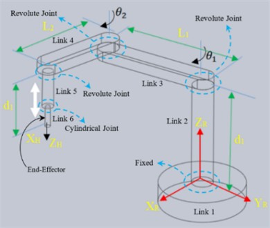
Direct kinematics calculates the position and orientation of a robot's links and end-effector based on its joint variables. The SCARA robot, characterized by its RRPR structure, employs a serial arm configuration with four degrees of freedom:
Eq. (1) can be utilized to derive the velocity relationship between the workspace and the robot's joints:
where is the Jacobian matrix, and a direct kinematics problem is solved using a 3D model of a modular robot consisting of 15 moving links and one fixed link. The geometrical and mechanical details of the modular robot are classified in Table 1 and Fig. 1. Furthermore, Table 1 is utilized for kinematic analysis and degrees of freedom, representing the robot as a rod mechanism to simplify the understanding and presentation of the associated mathematical relationships.
Table 1Assumed joints of modular robot within parameters’ value
Link | Length (m) | Mass (Kg) | Joint | Joint type | Degree of freedom | Axis | Parent to child |
1 | 0.3 | 0.5 | A | Revolute(motor) | Z | ||
2 | 0.2 | 0.75 | B | Fixed | – | ||
3 | 0.25 | 0.25 | C | Revolute(motor) | X | ||
4 | 0.15 | 1 | D | Fixed | – | ||
5 | 0.1 | 1.5 | E | Revolute(motor) | Y | ||
6 | 0.15 | 0.5 | F | Fixed | – | ||
7 | 0.2 | 0.75 | G | Revolute(motor) | Y | ||
8 | 0.12 | 0.25 | H | Fixed | – | ||
9 | 0.1 | 1 | I | Revolute(motor) | Y | ||
10 | 0.7 | 1.5 | J | Fixed | – | ||
11 | 0.1 | 0.5 | K | Revolute(motor) | Z | ||
12 | 0.15 | 0.75 | L | Fixed | – | ||
13 | 0.1 | 0.25 | M | Revolute(motor) | X | ||
14 | 0.5 | 1 | N | Fixed | – | ||
15 | 0.1 | 1.5 | P | Revolute(motor) | Y |
Based on Fig. 1, in the 2D schematic, 15 links’ angles are defined, and the links are joined at points that are defined in Table 1. In the 3D workspace, the modular mechanism is coupled with the right-hand side of the patient’s upper limb body, as shown in Fig. 2.
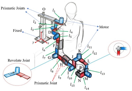
Similarly, a 3D model is presented in Fig. 3 to illustrate the robot's structure, its components, and interactions with humans, based on visual representations.
Fig. 1Two-dimensional design of the modular robot mechanism
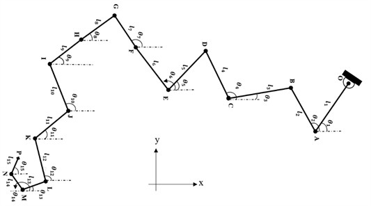
Fig. 2Three-dimensional schematic of the modular robot with joints
As examples, the first and last points of the modular robot are mathematically formulated as points O and P, respectively. The dynamic Eqs. (3-15) are obtained by setting up the Lagrangian of the mechanism and applying the Euler-Lagrange equations. Eq. (3) shows the inertial contribution (mass times acceleration), while Eqs. (4-5) capture the Coriolis and centrifugal forces that depend on joint velocities. Eq. (6) includes gravity effects on each joint. In biomechanical terms, these dynamics equations are similar to modeling how muscles (actuators) generate joint torques to move limb segments. For instance, if a link is heavy or extended (large inertia), the corresponding diagonal element of is larger, meaning more torque is needed for the same acceleration. The off-diagonal elements of indicate how motion in one joint can create forces in another, analogous to coupled muscle actions in multi-joint movements.
2.1.1. Joint O
Point O serves as a fixed coordinate reference, maintaining a constant position, velocity, and acceleration due to the absence of translational motion in Eqs. (3-5).
Coordination:
Velocity:
Acceleration:
2.1.2. Joint P
The point P as an end effector, representing the end-effector, has its three-dimensional position, angular velocity, and angular acceleration determined based on Eqs. (6-8) and the parameters of the preceding links. For simplicity, the and functions are abbreviated as , , and also the notation is used in the derivation of the kinematic equations:
Coordination:
Velocity:
Acceleration:
According to Fig. 1, there are various connection points between points O and P in the modular robot, which are detailed in the appendix section at the end of this paper.
2.2. Direct dynamic
The dynamics section examines the relationship between forces and kinematic parameters, deriving the differential equations of motion. Direct dynamics is employed for simulation, while inverse dynamics is used in control, path planning, and optimization. Key tasks include determining the coefficients of the motion equations, estimating inertial parameters, identifying unknown forces and accelerations, and conducting dynamic analysis in Eq. (9):
The external force corresponds to the force required to maintain equilibrium. The inertial matrix is represented by an × matrix in Eq. (10):
The dynamic equation, commonly used for robot control, can be expressed by Eq. (11) [35]:
In Eq. (11), the robot’s dynamics are governed by three equations: , , and , which represent the gravitational torques, Coriolis forces, and the external forces acting on the joints and body, respectively. The study examines a system with a uniform cross-sectional area, unknown but equal friction coefficients, a rigid object, linearly elastic contact, and touch sensors. Using the Lagrangian method, the dynamic equations for the SCARA robot are derived (see Fig. 3(a)), modelling the object's rigidity and friction coefficients as spring constants:
The vertical forces and act on the object, applied by the left and right jaws, respectively. Assuming symmetrical movement, the object has three degrees of freedom (in the , , and directions) without rotation. The resulting Eq. (13) of motions is provided below:
where, the represents the frictional force on the object’s surface, while and denote the mass and weight, correspondingly. The study investigates the dynamics of a system, focusing on the force and torque components. The modular robot’s mechanism is described using the Cartesian coordinates, with fundamental relations derived from Newton's second law and D'Alembert's principle in Eqs. (14) and (15):
To express the modular robot’s dynamics directly based on D’Alembert’s law, it can rewrite the system as follows:
The parameters used in the preceding relationship are summarized in Table 3. The frictional relationship consists of two components: friction at the joints and friction between the skin of the members. This relationship can be expressed as Eq. (16):
Consequently, the components used in Eq. (16) are defined in Table 4.
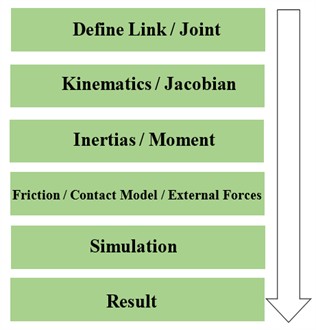
All simulations are carried out in MATLAB using an ordinary differential equation solver that is the numerical differences and approximate derivatives so-called Y = diff(X), velocity and acceleration are obtained by velocity = diff(displacement), and acceleration = diff(velocity), respectively. Simulation works with relative tolerance 1e-6, absolute tolerance 1e-9, and a fixed time step of 0.01 s. The simulation horizon was 10 seconds. Ultimately, the source code of this paper has been uploaded in [36]. Initial joint states were and . The simulation outline is worked based on Fig. 3(b).
Table 2Dynamical parameters
Definition | Parameter |
Inertia matrix | |
Angle | |
Angular velocity | |
Angular acceleration | |
Central torque and Coriolis torque | |
Joint friction | |
Error and uncertainty | |
Jacobian matrices | , |
Friction between joints | |
Friction between links’ skin |
Fig. 3a) Three-dimensional SCARA robot, b) modeling simulation process in this research
a)
b)
3. Result and discussion
3.1. Kinematics and dynamics
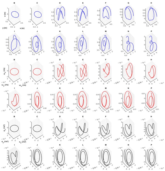
In this section, the results of the simulation modeling in kinematics, dynamics, stability, and sensitivity analyses are presented. These analyses were formulated in the previous section, and Figs. 4 to 8 display the displacement, velocity, acceleration, and torque responses of each link of the modular robot (the configuration of the system is shown in Fig. 1). Joint O serves as the first support and base of the modular robot; accordingly, it remains fixed and exhibits zero displacement, zero velocity, and zero acceleration. Using Eqs. (6-8) (and the complete kinematic derivation in the Appendix, covering Eqs. (17-58), the motions of joints A through N are computed in three Cartesian directions for displacements, velocities, and accelerations. Fig. 4 shows translational displacements (blue curves), angular velocities (red curves), and angular accelerations (black curves) in the , , and directions under prescribed motion patterns that align with typical upper-limb rehabilitation ranges of motion. The smooth and continuous nature of the displacement curves indicates that the motion-planning algorithm yields trajectories resembling natural limb movements. Such smooth trajectories enhance patient comfort and support motor learning in rehabilitation contexts (see e.g., [37-39]). Joint displacements remain within physiological limits, which is essential for safe rehabilitation use, avoiding hyperextension or unnatural joint angles (see e.g., [40]). The angular velocity profiles show gradual increases and decrease in amplitude. This profile avoids abrupt jumps in speed and thus reduces potential discomfort for patients. The peak velocity values fall within therapeutic windows – neither extremely slow nor excessively fast – contributing to safe and effective interaction. The angular accelerations (obtained through differentiation of the angular velocities) reflect the rate of change of velocity during movement. These acceleration curves remain within safe operational thresholds, thereby preventing excessive dynamic forces on the patient’s limb (see e.g., [38, 41]). Consistency in acceleration profiles across different joints highlights uniform motion throughout the mechanism, a desirable property in rehabilitation robotics where coordinated movement is critical. Moreover, the absence of rapid fluctuations in acceleration reduces potential mechanical vibration or resonance in the robot structure, further improving comfort and mechanical reliability (see e.g., [42]). In the subplots of Fig. 5, derived from Eqs. (9-16), the direct dynamics of the modular robot are shown – comprising total, inertial, Coriolis, and gravitational torque components across all links. The torque profiles exhibit clear peaks (for example, approximate values: joint 1 ≈ 2.5 Nm, joint 2 ≈ 1 Nm). These peak values provide critical input for actuator selection. Actuators – either geared motors or Series Elastic Actuators (SEAs) – should have continuous and peak torque ratings exceeding these simulated values by an adequate safety margin. The SEAs are widely adopted in rehabilitation and assistive robotic systems for precise torque control and mechanical compliance, ensuring both safety and accurate force feedback (see e.g., [43-45]). When compared to existing hardware, many upper-limb rehabilitation robots employ actuators within the 10-50 Nm range. For instance, the MAHI Exo-II wrist rehabilitation robot and similar devices utilize brushless DC motors rated around 20-25 Nm peak (see e.g., [46]).
Fig. 4Displacement, velocity, acceleration in three directions for all points
The relatively smaller torques predicted in this study (2.5 Nm and 1 Nm) suggest that the proposed modular mechanism is lightweight and energy-efficient. Nonetheless, maintaining a 20-30 % torque margin remains advisable to accommodate unmodeled effects such as friction, wear, and safety considerations (see e.g., [44, 47]). Motor speed and gearing ratios should also be selected to ensure that the simulated angular velocities are physically achievable. Beyond noting that Coriolis torques are relatively small, the torque decomposition provides valuable guidance for actuator and transmission design. Since inertial and gravitational torques dominate, actuator selection must ensure adequate capacity to handle these loads under worst-case motion. Although smaller in magnitude, Coriolis torques are still essential for ensuring responsiveness and smooth control during dynamic rehabilitation tasks (see e.g., [43, 48]).
Fig. 5Total torques, inertial, Coriolis, gravitational on acting on all links
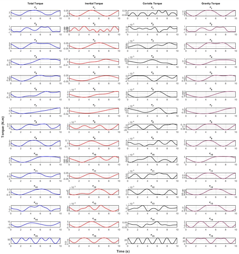
Understanding the relative magnitude of each torque component helps optimize actuator efficiency, thermal performance, and control bandwidth. Overall, Fig. 5 validates the mechanical design of the modular robot and highlights how gravitational loading and inertial properties influence actuation demands. These insights are essential for designing a rehabilitation system that meets mechanical requirements while maintaining safety, comfort, and energy efficiency (see e.g., [49]). The simulation results are subject to certain limitations stemming from key modeling assumptions. (i) The links are modeled as perfectly rigid; thus high-frequency structural or elastic effects (such as link flexing or vibration) are not captured. (ii) Friction is simplified to coarse joint and contact terms and does not represent complex behaviors such as Stribeck friction or micro-slip at the robot-patient interface (see e.g., [50, 51]). (iii) Symmetry assumptions – identical link geometry and mass – simplify the model but may not hold in real systems due to manufacturing tolerances or asymmetric human loading. These simplifications may result in underestimation of torque requirements or overlooked vibration and comfort effects in practice. Future work should incorporate detailed friction and compliance models, asymmetric parameters, and experimental validation with a physical prototype to refine actuator sizing, control design, and patient–robot interaction safety (see e.g., [52]).
3.2. Stability analysis
This subsection represents stability displacements in three directions. especially the end-effector of the modular robot, because of two significant reasons: firstly, the end-effector is the main link connected to the user; therefore, it has the main role to perform correctly and support the user’s demands; secondly, the end-effector is the final link attached to the previous 14 links; hence, it can show any faults if there are any in the previous links.
Fig. 6Stability analysis results in end-effector
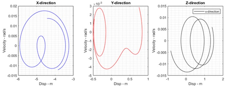
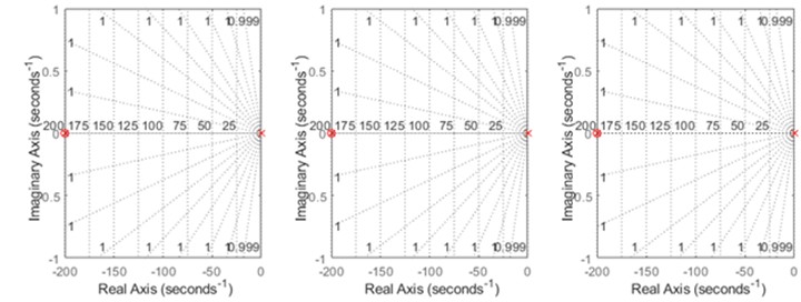
The Fig. 6 demonstrates stability analyses of the end-effector in different positions and directions; that means the displacement and velocity of the end-effector are input and output, respectively. Furthermore, in each direction, roots of the transfer function of the modular robot are plotted as real-imaginary figures based on the criteria of the Routh-Hurwitz stability. The roots are located on the left-hand side of the complex plane; it proves that the robot performs in stable conditions.
3.3. Sensitivity analysis
This section analyzes geometrical and dynamical sensitivities globally through parameters; for example, in kinematics, the length of links and in dynamics, the mass of links that are varied by adding and subtracting a reasonable value. This method is known as the perturbation approach.
Table 3Sensitivity analysis of the kinematics and dynamics of the modular robot
Type Approach | Peturbution 1 | Peturbution 2 |
Kinematics (m) | ||
Dynamics (Kg) |
Based on the former table, 0.15 meter and 1.5 kg are added and subtracted from the length and mass of the links, respectively. Perturbing parameters such as the length and mass of the links are restimulated by the program based on Table 3, which is shown in Figs. 7 and 8. The comparison includes the displacement and torque of the end effector as examples, highlighting their errors due to two perturbations, which demonstrates that this modeling is concise enough to remain stable and robust against variations in parameters such as length and mass.
Fig. 7Comparison of end effector displacement sensitivities with the original case and perturbations 1 and 2
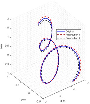
a) Displacements of the eneffector
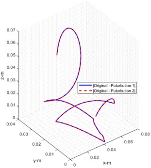
b) Error of displacements
Fig. 8Comparison of torque sensitivities with the original case and perturbations 1 and 2
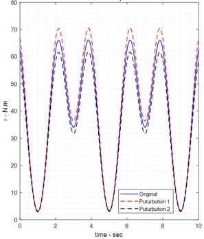
a) Total torque
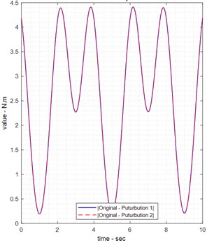
b) Error of torque
In summary, the current simplified model likely underestimates the complexity of a real robot. Before hardware implementation, the design should be validated experimentally. In a physical prototype, one would measure actual joint friction and link stiffness and adjust the control and torque estimates accordingly. Despite these limitations, the current model provides a clear baseline of the expected torques; more detailed models (including joint compliance or measured friction) can be developed in future work to refine these predictions. This paper notes that these simplifications could affect real-world performance. Unequal friction at the joints would mean one joint could need significantly more torque than predicted here. Any asymmetry in link shape or mass would also change inertia values. Furthermore, treating links as perfectly rigid ignores vibrations or deflection that might occur under load, which could slightly change the effective torques. In other words, the model’s torque outputs represent idealized values; actual required torques might be higher once all real factors are included. Therefore, the results should be considered as a first estimate, with future work needed to incorporate detailed friction models, link compliance, and validate the predictions for a real rehabilitation robot.
4. Conclusions
This paper introduces a first-of-its-kind modular robotic system for upper-limb rehabilitation that combines mechanical reconfigurability, symmetric left/right operation, and nonlinear model-based control to support therapy of the wrist, elbow, and shoulder – individually or in coordinated multi-joint modes. Key results from the analytic and simulation studies demonstrate that the modular architecture (i) reproduces physiologically relevant kinematic workspaces across multiple configurations, (ii) yields numerically stable dynamic responses under representative disturbances when controlled with the proposed torque/force controllers, and (iii) enables on-the-fly adaptation of workspace and impedance to accommodate differing patient needs. The analyses (kinematic reachability, Jacobian conditioning, inertia distribution, and closed-loop torque tracking) provide quantitative evidence that a single modular platform can achieve the motion fidelity and interaction safety required for clinically meaningful rehabilitation tasks. This article carefully derived nonlinear dynamic models (inertia, Coriolis/centrifugal, and gravity g) and separated friction/contact effects to support controller design. The bold finding is that model-based torque/force control substantially improves disturbance rejection and reduces steady-state tracking errors in simulation relative to threshold-based methods (see Results and Discussion). These findings establish a firm theoretical basis for motor selection, energy budgeting, and control tuning in future hardware implementations. The current work is primarily analytic and simulation-based; several simplifying assumptions were adopted to make the modeling tractable (rigid links, symmetric grasp/contact, uniform mass distributions, and simplified friction models). These assumptions limit the prediction of high-frequency structural responses, asymmetric contact phenomena, and detailed Stribeck friction effects. Sensor models included additive Gaussian noise but do not yet capture sensor drift, intermittent faults, or bandwidth limitations that occur in practice. Therefore, it emphasizes that absolute numerical values reported here should be treated as indicative; relative performance comparisons across configurations and control laws are the most reliable outcomes of this study. To translate the concept into a clinical research prototype, a staged plan is recommended: bench-level component tests (instrumented rotors and bearings), subsystem integrations (actuated joint modules with onboard sensing and local control), and a system-level test rig for human-in-the-loop trials under institutional review. Acceptance criteria should include reproducible detection lead time for incipient faults, bounded interaction forces within safety limits, and end-to-end delay compatible with real-time impedance control. These experimental steps will also enable identification of realistic friction/inertia parameters and sensor noise models for improved model-based control. In the last sub-sections are demonstrated stable operations of the robot by stability and sensitivity analyses that are focused on displacement and velocity of the end-effector. In detail, stability analysis shows the stable status of the end-effector because the roots of the transfer function of the robot are negatively positioned on the left-hand side of the real-imaginary axes, which agrees with the stability based on the important criteria in control engineering so-called Routh-Hurwitz. In the last sub-section, the sensitivity of the end-effector is displayed as perturbed by adding and reducing values of length and mass for mathematical kinematics and dynamics in each link.
References
-
L. Zhang, S. Guo, and Q. Sun, “An assist-as-needed controller for passive, assistant, active, and resistive robot-aided rehabilitation training of the upper extremity,” Applied Sciences, Vol. 11, No. 1, p. 340, Dec. 2020, https://doi.org/10.3390/app11010340
-
M. Kyrarini et al., “A survey of robots in healthcare,” Technologies, Vol. 9, No. 1, Jan. 2021, https://doi.org/10.3390/technologies9010008
-
I. Aprile et al., “Upper limb robotics in rehabilitation: an approach to select the devices, based on rehabilitation aims, and their evaluation in a feasibility study,” Applied Sciences, Vol. 9, No. 18, p. 3920, Sep. 2019, https://doi.org/10.3390/app9183920
-
S. Cai, G. Huang, L. Huang, and L. Xie, “Kinematics analysis, design, and simulation of a dual-arm robot for upper limb physiotherapy,” IOP Conference Series: Materials Science and Engineering, Vol. 397, p. 012049, Aug. 2018, https://doi.org/10.1088/1757-899x/397/1/012049
-
H. Ren, T. Liu, and J. Wang, “Design and analysis of an upper limb rehabilitation robot based on multimodal control,” Sensors, Vol. 23, No. 21, p. 8801, Oct. 2023, https://doi.org/10.3390/s23218801
-
M. R. Islam, M. Assad-Uz-Zaman, B. Brahmi, Y. Bouteraa, I. Wang, and M. H. Rahman, “Design and development of an upper limb rehabilitative robot with dual functionality,” Micromachines, Vol. 12, No. 8, p. 870, Jul. 2021, https://doi.org/10.3390/mi12080870
-
T. Nef, M. Guidali, and R. Riener, “ARMin III – arm therapy exoskeleton with an ergonomic shoulder actuation,” Applied Bionics and Biomechanics, Vol. 6, No. 2, pp. 127–142, Jul. 2009, https://doi.org/10.1080/11762320902840179
-
P. Maciejasz, J. Eschweiler, K. Gerlach-Hahn, A. Jansen-Troy, and S. Leonhardt, “A survey on robotic devices for upper limb rehabilitation,” Journal of NeuroEngineering and Rehabilitation, Vol. 11, No. 1, Jan. 2014, https://doi.org/10.1186/1743-0003-11-3
-
S. H. Lee et al., “Comparisons between end-effector and exoskeleton rehabilitation robots regarding upper extremity function among chronic stroke patients with moderate-to-severe upper limb impairment,” Scientific Reports, Vol. 10, No. 1, p. 2020, Feb. 2020, https://doi.org/10.1038/s41598-020-58630-2
-
Y. Liu, Q. Song, C. Li, X. Guan, and L. Ji, “Quantitative assessment of motor function for patients with a stroke by an end‐effector upper limb rehabilitation robot,” BioMed Research International, Vol. 2020, No. 1, Apr. 2020, https://doi.org/10.1155/2020/5425741
-
Y. Liu et al., “Development and implementation of an end-effector upper limb rehabilitation robot for hemiplegic patients with line and circle tracking training,” Journal of Healthcare Engineering, Vol. 2017, pp. 1–11, Jan. 2017, https://doi.org/10.1155/2017/4931217
-
Q. Meng, Z. Jiao, H. Yu, and W. Zhang, “Design and evaluation of a novel upper limb rehabilitation robot with space training based on an end effector,” Mechanical Sciences, Vol. 12, No. 1, pp. 639–648, Jun. 2021, https://doi.org/10.5194/ms-12-639-2021
-
C. Qian et al., “Quantitative assessment of motor function by an end-effector upper limb rehabilitation robot based on admittance control,” Applied Sciences, Vol. 11, No. 15, p. 6854, Jul. 2021, https://doi.org/10.3390/app11156854
-
M. Li, J. Zhang, G. Zuo, G. Feng, and X. Zhang, “Assist-as-needed control strategy of bilateral upper limb rehabilitation robot based on GMM,” Machines, Vol. 10, No. 2, p. 76, Jan. 2022, https://doi.org/10.3390/machines10020076
-
L. Li, J. Han, X. Li, B. Guo, and X. Wang, “Customized trajectory optimization and compliant tracking control for passive upper limb rehabilitation,” Sensors, Vol. 23, No. 15, p. 6953, Aug. 2023, https://doi.org/10.3390/s23156953
-
Z. Wang, Z. Cai, L. Cui, and C. Pang, “Structure design and analysis of kinematics of an upper-limbed rehabilitation robot,” in MATEC Web of Conferences, Vol. 232, p. 02033, Nov. 2018, https://doi.org/10.1051/matecconf/201823202033
-
Z. Pang, T. Wang, Z. Wang, J. Yu, Z. Sun, and S. Liu, “Design and analysis of a wearable upper limb rehabilitation robot with characteristics of tension mechanism,” Applied Sciences, Vol. 10, No. 6, p. 2101, Mar. 2020, https://doi.org/10.3390/app10062101
-
T. Ahmed, M. R. Islam, B. Brahmi, and M. H. Rahman, “Robustness and Tracking performance evaluation of PID motion control of 7 DoF anthropomorphic exoskeleton robot assisted upper limb rehabilitation,” Sensors, Vol. 22, No. 10, p. 3747, May 2022, https://doi.org/10.3390/s22103747
-
H. I. Krebs et al., “Rehabilitation robotics: pilot trial of a spatial extension for MIT-Manus,” Journal of NeuroEngineering and Rehabilitation, Vol. 1, No. 1, Oct. 2004, https://doi.org/10.1186/1743-0003-1-5
-
W. H. Chang and Y.-H. Kim, “Robot-assisted therapy in stroke rehabilitation,” Journal of Stroke, Vol. 15, No. 3, p. 174, Jan. 2013, https://doi.org/10.5853/jos.2013.15.3.174
-
F. Durante, T. Raparelli, and P. Beomonte Zobel, “Two-Dof upper limb rehabilitation robot driven by straight fibers pneumatic muscles,” Bioengineering, Vol. 9, No. 8, p. 377, Aug. 2022, https://doi.org/10.3390/bioengineering9080377
-
X. Chen, S. Zhang, K. Cao, C. Wei, W. Zhao, and J. Yao, “Development of a wearable upper limb rehabilitation robot based on reinforced soft pneumatic actuators,” Chinese Journal of Mechanical Engineering, Vol. 35, No. 1, Jun. 2022, https://doi.org/10.1186/s10033-022-00749-6
-
L. Zhang, S. Guo, and Q. Sun, “Development and assist-as-needed control of an end-effector upper limb rehabilitation robot,” Applied Sciences, Vol. 10, No. 19, p. 6684, Sep. 2020, https://doi.org/10.3390/app10196684
-
I. B. Abdallah and Y. Bouteraa, “An optimized stimulation control system for upper limb exoskeleton robot-assisted rehabilitation using a fuzzy logic-based pain detection approach,” Sensors, Vol. 24, No. 4, p. 1047, Feb. 2024, https://doi.org/10.3390/s24041047
-
R. Hong, B. Li, Y. Bao, L. Liu, and L. Jin, “Therapeutic robots for post-stroke rehabilitation,” Medical Review, Vol. 4, No. 1, pp. 55–67, Feb. 2024, https://doi.org/10.1515/mr-2023-0054
-
A. B. Payedimarri, M. Ratti, R. Rescinito, K. Vanhaecht, and M. Panella, “Effectiveness of platform-based robot-assisted rehabilitation for musculoskeletal or neurologic injuries: a systematic review,” Bioengineering, Vol. 9, No. 4, p. 129, Mar. 2022, https://doi.org/10.3390/bioengineering9040129
-
R. Feingold-Polak, O. Barzel, and S. Levy-Tzedek, “A robot goes to rehab: a novel gamified system for long-term stroke rehabilitation using a socially assistive robot-methodology and usability testing,” Journal of NeuroEngineering and Rehabilitation, Vol. 18, No. 1, Jul. 2021, https://doi.org/10.1186/s12984-021-00915-2
-
K. Nizamis, A. Athanasiou, S. Almpani, C. Dimitrousis, and A. Astaras, “Converging robotic technologies in targeted neural rehabilitation: a review of emerging solutions and challenges,” Sensors, Vol. 21, No. 6, p. 2084, Mar. 2021, https://doi.org/10.3390/s21062084
-
I. Aprile et al., “Upper limb robotic rehabilitation after stroke: a multicenter, randomized clinical trial,” Journal of Neurologic Physical Therapy, Vol. 44, No. 1, pp. 3–14, Jan. 2020, https://doi.org/10.1097/npt.0000000000000295
-
T. Johansen, L. Sørensen, K. K. Kolskår, V. Strøm, and M. F. Wouda, “Effectiveness of robot-assisted arm exercise on arm and hand function in stroke survivors – A systematic review and meta-analysis,” Journal of Rehabilitation and Assistive Technologies Engineering, Vol. 10, Jun. 2023, https://doi.org/10.1177/20556683231183639
-
A. Guatibonza, L. Solaque, A. Velasco, and L. Peñuela, “Assistive robotics for upper limb physical rehabilitation: a systematic review and future prospects,” Chinese Journal of Mechanical Engineering, Vol. 37, No. 1, Jul. 2024, https://doi.org/10.1186/s10033-024-01056-y
-
D. Simonetti, L. Zollo, L. Vollero, G. Iannello, and E. Guglielmelli, “A modular telerehabilitation architecture for upper limb robotic therapy,” Advances in Mechanical Engineering, Vol. 9, No. 2, Feb. 2017, https://doi.org/10.1177/1687814016687252
-
G. Airò Farulla et al., “Vision-based pose estimation for robot-mediated hand telerehabilitation,” Sensors, Vol. 16, No. 2, p. 208, Feb. 2016, https://doi.org/10.3390/s16020208
-
L. Zhang, X. Tian, Y. Fan, T. Jiang, S. Gu, and L. Xu, “Development and efficacy assessment of an angle sensor-integrated upper limb exoskeleton system for autonomous rehabilitation training,” Sensors, Vol. 25, No. 13, p. 3984, Jun. 2025, https://doi.org/10.3390/s25133984
-
R. S. Calabrò et al., “Robotic gait rehabilitation and substitution devices in neurological disorders: where are we now?,” Neurological Sciences, Vol. 37, No. 4, pp. 503–514, Jan. 2016, https://doi.org/10.1007/s10072-016-2474-4
-
“modular rehabilitation robot.” GitHub repository, https://github.com/negarpajooh/modular_rehabilitation_robot
-
L. Marchal-Crespo and D. J. Reinkensmeyer, “Review of control strategies for robotic movement training after neurologic injury,” Journal of NeuroEngineering and Rehabilitation, Vol. 6, No. 1, Jun. 2009, https://doi.org/10.1186/1743-0003-6-20
-
H. I. Krebs et al., “Rehabilitation robotics: performance-based progressive robot-assisted therapy,” Autonomous Robots, Vol. 15, No. 1, pp. 7–20, Jul. 2003, https://doi.org/10.1023/a:1024494031121
-
T. Nef and R. Riener, “ARMin – design of a novel arm rehabilitation robot,” in 9th International Conference on Rehabilitation Robotics, 2005. ICORR 2005., pp. 57–60, Nov. 2025, https://doi.org/10.1109/icorr.2005.1501051
-
J. C. Perry, J. Rosen, and S. Burns, “Upper-limb powered exoskeleton design,” IEEE/ASME Transactions on Mechatronics, Vol. 12, No. 4, pp. 408–417, Aug. 2007, https://doi.org/10.1109/tmech.2007.901934
-
M. A. Ergin et al., “ASSISTON-SE: A self-aligning shoulder-elbow exoskeleton,” in IEEE International Conference on Robotics and Automation (ICRA), Vol. 31, No. 13, pp. 2479–2485, May 2012, https://doi.org/10.1109/icra.2012.6225117
-
B. Noronha et al., “Soft, lightweight wearable robots to support the upper limb in activities of daily living: a feasibility study on chronic stroke patients,” IEEE Transactions on Neural Systems and Rehabilitation Engineering, Vol. 30, pp. 1401–1411, Jan. 2022, https://doi.org/10.1109/tnsre.2022.3175224
-
J. Vantilt et al., “Model-based control for exoskeletons with series elastic actuators evaluated on sit-to-stand movements,” Journal of NeuroEngineering and Rehabilitation, Vol. 16, No. 1, Jun. 2019, https://doi.org/10.1186/s12984-019-0526-8
-
E. Bolivar, S. Rezazadeh, T. Summers, and R. D. Gregg, “Robust optimal design of energy efficient series elastic actuators: application to a powered prosthetic ankle,” 2019 IEEE 16th International Conference on Rehabilitation Robotics (ICORR), pp. 740–747, Jun. 2019, https://doi.org/10.1109/icorr.2019.8779446
-
C. Zhao, Z. Liu, L. Zhu, and Y. Wang, “Design and research of series actuator structure and control system based on lower limb exoskeleton rehabilitation robot,” Actuators, Vol. 13, No. 1, p. 20, Jan. 2024, https://doi.org/10.3390/act13010020
-
M. I. Awad, I. Hussain, S. Ghosh, Y. Zweiri, and D. Gan, “A double-layered elbow exoskeleton interface with 3-prr planar parallel mechanism for axis self-alignment,” Journal of Mechanisms and Robotics, Vol. 13, No. 1, Feb. 2021, https://doi.org/10.1115/1.4048428
-
Q. Zhang, D. Sun, W. Qian, X. Xiao, and Z. Guo, “Modeling and control of a cable-driven rotary series elastic actuator for an upper limb rehabilitation robot,” Frontiers in Neurorobotics, Vol. 14, Feb. 2020, https://doi.org/10.3389/fnbot.2020.00013
-
B. Deboon, S. Nokleby, N. La Delfa, and C. Rossa, “Differentially-clutched series elastic actuator for robot-aided musculoskeletal rehabilitation,” International Conference on Robotics and Automation (ICRA), pp. 1507–1513, May 2019, https://doi.org/10.1109/icra.2019.8793586
-
H. I. Krebs and N. Hogan, “Robotic therapy,” American Journal of Physical Medicine and Rehabilitation, Vol. 91, No. 11, pp. S290–S297, Nov. 2012, https://doi.org/10.1097/phm.0b013e31826bcd80
-
B. Silva and N. Kottege, “Accessible torque bandwidth of a series elastic actuator considering the thermodynamic limitations,” arXiv:2011.06217, Jan. 2020, https://doi.org/10.48550/arxiv.2011.06217
-
A. Stentz, “Optimal and efficient path planning for partially-known environments,” in IEEE International Conference on Robotics and Automation, pp. 3310–3317, Dec. 2025, https://doi.org/10.1109/robot.1994.351061
-
N. Hogan et al., “Motions or muscles? Some behavioral factors underlying robotic assistance of motor recovery,” The Journal of Rehabilitation Research and Development, Vol. 43, No. 5, p. 605, Jan. 2006, https://doi.org/10.1682/jrrd.2005.06.0103
About this article

The authors have not disclosed any funding.
The datasets generated during and/or analyzed during the current study are available from the corresponding author on reasonable request.
The authors declare that they have no conflict of interest.
