Abstract
This paper presents the design and the simulation of an exoskeleton based on the kinematics of the human arm intended to be used in robot-assisted rehabilitation of the upper limb. The design meets the kinematic characteristics of the human arm so that the exoskeleton allows the movement of the arm in its full range of motion. We used co-simulation to design the exoskeleton considering a model of the upper limb developed in Opensim, Solidworks to design the mechanical structure and Matlab to construct the dynamic model. The system in motion was simulated in Simmechanics using predictive dynamics to compute independent joint trajectories obtained by modelling the exoskeleton as several optimization problems solved with SNOPT from Tomlab. The use of virtual tools in the designing process and the modular structure of the exoskeleton will allow the construction of personalized devices using 3D printing. The exoskeleton was designed to work under independent joint control so that the system will be able to work as passive, assistive and active-assistive mode, to keep records of motion for data analysis and to support the rehabilitation process.
1. Introduction
Motor dysfunction in the upper limb is a frequent impairment that may become chronic in poststroke individuals affecting the execution of regular motor tasks such as picking up an object [1]. Survivors poststroke can drive neural reorganization brain recovery and return of function with task specific repetitive training [2]. Traditional therapy consists of repetitive positioning and range of motion (ROM) exercises, mobilization, compensatory techniques, strengthening and endurance training. After stroke, exercise therapy combined with healthcare practice supported by electronic devices (e-health) has helped to the recovery of the patient by taking advantage of virtual environments designed to encourage individuals to execute particular movements [3-5]. Robot assisted devices are frequently used in e-health for upper limb rehabilitation due to its capability to adapt to different types of therapy. Robotic devices are used to facilitate early recovery of locomotion in shoulder, elbow, wrist and fingers [6-9]. It has been shown that the use of robot mediated devices to support rehabilitation treatments for motor impairment in the upper limb in stroke survivors, can be reduced significantly the impairment measures of the affected limb [10].
Robot-mediated rehabilitation for the upper limb includes various types of modalities such as passive, active-passive and resistive. These modalities have been classified recently by Basteris and colleagues according to the features of their implementation: active (Ac), assistive (As), passive (P), passive-mirrored (PM), active-assistive (AA), corrective (C), path guidance (PG) and resistive (R). Active mode is based in the solely contribution of the user in the execution of a task, in passive mode the robot is in charge of the motion, whereas in assistive mode both the patient and the robot contribute to the task execution. Passive mirrored mode is used in bimanual devices when the subject executes a movement with the healthy arm to be reproduced by the impaired arm. In active-assistive mode the robot corrects the user when he/she is not performing correctly during the task whereas in corrective mode the robot stops the user under the same circumstances so the user can retake the task. In resistive mode the robot resists the movement that the user is executing. In path guidance mode the user executes a trajectory haptically guided by the robot [11].
Robot exoskeletons are wearable articulated mechanic structures whose kinematics are based on the kinematics of the human arm. The motion of each articulation can be controlled through powered motors and position sensors located in the joints of the structure. This work focused on the design of an eight degrees of freedom (DOF) exoskeleton that is expected to perform in passive, assistive and active-assistive mode. Among popular robot-mediated devices that had been in the field of study during past years, that perform under one of more of these modalities, we can mention the active-assistive arm exoskeleton BONES, the active-assistive KINARM hybrid exoskeleton, the assistive MAHI EXO-II and the active L-Exos robotic exoskeletons. The Biomimetic Orthosis for the Neurorehabilitation of the Elbow and the Shoulder BONES is a pneumatically powered exoskeleton whose kinematic design replicates the normal range of motion of the human arm. The control system of BONES can be programmed so assistance algorithms can be added according to the needs of the user [12]. The KINARM exoskeleton is a commercial device that uses linkages that allows the motion of the elbow and shoulder in the horizontal plane. The control system of the KINARM records pattern of motions and joint torques independently in order to replicate tasks or to apply loads [13]. The MAHI EXO-II is a 5-DOF robotic exoskeleton built with two revolute joints for the elbow and the forearm, and one spherical joint for the wrist actuated with DC brush motor. The design of the MAHI EXO-II allows the user to record the movement of each joint independently for an accurate knowledge of the arm and wrist movement. [14, 15]. The L-Exo is a 5-DOF exoskeleton, it is a force-feedback anthropomorphic arm with four joints that are actuated to permit the ROM of the shoulder and elbow. The system also has a passive joint that allows the wrist movement [16, 17].
In this paper we present the design and the simulation of an exoskeleton based on the kinematics of the human arm intended to be used in robot-assisted rehabilitation of the upper limb. The proposed device is an eight DOF mechanical structure with independent revolute joints that will allow the user to move the arm in its full ROM. The exoskeleton was developed in co-simulation of a software for musculoskeletal modelling and simulation of movement (Opensim), a computer aided design software (Solidworks) and a simulation environment for mechanical systems (MATLAB-Simmechanics). Fig. 1 shows the flowchart containing the elements used during the development of the system. First we used a model of the upper limb developed in Opensim that provided the kinematics of a human arm as a base to design the exoskeleton structure in Solidworks. The Solidworks structure provided the physical characteristics and the inertial data of the exoskeleton that was later used to construct the dynamic model in Matlab. Since the upper limb model provided data to simulate an elbow rotation only, we used predictive dynamics (PD) to compute independent trajectories for each joint of the exoskeleton considering the ROM of the human arm. We modeled the exoskeleton as optimization problems based on the dynamic model of the system using SNOPT from Tomlab to solve them. Finally, we simulated the exoskeleton in Simmechanics considering the joint trajectories obtained using PD. The experimental section gives an insight of the design process of the exoskeleton in Solidworks and the simulation of the exoskeleton dynamic model in Simmechanics. The last two sections analyses the results of the simulations and discuss the pertinence of the exoskeleton according to the design objectives.
2. Experimental section
2.1. Design objectives
The design of the exoskeleton considered specific characteristics so, once built, the robotic device could be successfully used for assistance and restoration of locomotion. The main objective of the design is that it has to meet the kinematic characteristics of the human arm considering independent joint control so that the exoskeleton allows the movement of the anatomical center of rotation during locomotion [18]. An anthropomorphic design would allow full ROM of the human arm for the execution of several movements and activities of daily living (ADL) [19]. The exoskeleton is intended to support the rehabilitation of poststroke patients by being able to increase the intensity of training, in order to allow users to practice motor tasks by themselves with a natural and intuitive interaction [20]. The design must consider safety and dependability, easy of wearability and portability and usability/acceptance [21, 22]. Finally, the system must have the capability to keep a record of each joint movement in order to monitor and analyze isolated movements [14].
2.2. Biomechanics of the human arm
The kinematics of the upper limb is based in the locomotion of the scapula, the shoulder, the forearm and the hand. Altogether, as a combination of two or more, or by performing independent movements these elements of the arm are responsible for positioning the hand in space. Each element involved in the kinematics of the upper limb has at least one DOF with a limited range of motion as described in Table 1. Among the movements involved in hand positioning tasks are: the scapula flexion/extension; the shoulder flexion/extension, adduction/abduction, median/lateral rotation; the elbow flexion/extension; the forearm pronation/supination, the hand abduction/adduction and flexion/extension [23].
2.2.1. Simulation of an arm movement
The design of the exoskeleton was based on an accurate model of the human arm of a 50 percentile male (170 cm tall) developed by Holzbaur and colleagues. The model defines the kinematics of the human arm as a 15 DOF system that includes three DOF for the shoulder, two DOF for the elbow, two DOF for the wrist, four DOF for the index finger and four DOF for the thumb [24]. The model was developed using Opensim which is a platform developed by Delp and colleagues in Stanford University for modelling and simulation of the neuroskeletal system [25]. We used the described model to define the kinematics of the exoskeleton. The model of the arm in Opensim includes the inverse kinematics simulation for an elbow rotation from 0 to 90 degrees.
Table 1Elements of the upper limb and their range of motion
DOF | Movement | Angles of rotation (degrees) lower limit/upper limit | |
Scapula | 1 | Flexion/extension | 20/15 |
Shoulder | 1 | Flexion/extension | 140-180/60 |
2 | Medial/lateral | 90/20 | |
3 | Abduction/adduction | 180/20 | |
Elbow | 1 | Flexion/extension | 150/10 |
Forearm | 1 | Pronation/supination | 90/80 |
Wrist | 1 | Abduction/adduction | 25-30/30-40 |
2 | Flexion/extension | 60-80/60-90 |
2.3. Design specifications
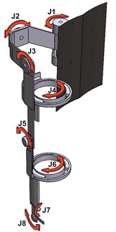
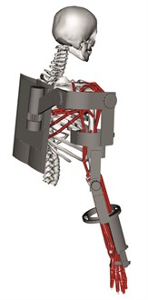
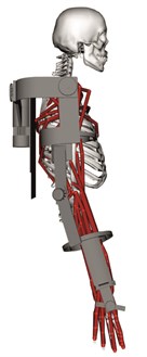
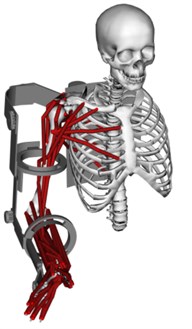
The mechanical structure of the exoskeleton was designed in Solidworks. The exoskeleton is an eight DOF based on the upper limb ROM described in Table 1. The dimensions of the exoskeleton elements are based on the dimensions of the human arm model of the 50 percentile male [24]. Fig. 2 shows the schematic of the exoskeleton mechanical structure. Fig. 2(a) shows the structure of the exoskeleton with its eight DOF. All joints J1, J2, J3, J4, J5, J6, J7 and J8 are revolute. The back side of the exoskeleton, shown in Fig. 2(b), serves as support for the exoskeleton and it is also thought to hold the batteries. A side view of the exoskeleton in its initial pose is shown in Fig. 2(c). Fig. 2(d) shows the human arm and the exoskeleton when the elbow is in a 90 degrees position.
Fig. 1Mechanical structure of the exoskeleton: a) Schematic and degrees of freedom, b) back and c) side view of the exoskeleton fitted to the human arm model, d) the exoskeleton and the human arm when the elbow is in a 90 degrees position
a)
b)
c)
d)
2.3.1. Joint layout
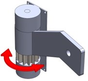
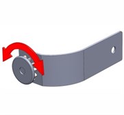
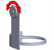
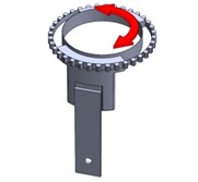
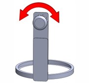
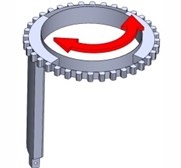
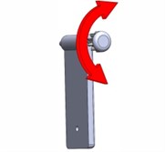
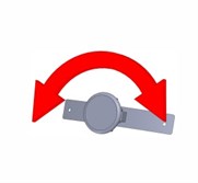
The structure is built by eight mobile parts or links displayed in Fig. 3. Fig. 3(a) shows the element responsible for the scapula flexion/extension movements. The elements in Fig. 3(b), Fig. 3(c) and Fig. 3(d) allow the abduction/adduction, flexion/extension and medial/lateral of the shoulder. The element in Fig. 3(e) allows the elbow flexion/extension. The element in Fig. 3(f) allows the forearm pronation/supination movements. The elements in Fig. 3(g) and Fig. 3(h) allow the hand abduction/adduction and flexion/extension, respectively.
2.3.2. Dynamic model
The dynamic model of the exoskeleton is represented as Eq. (1):
where is the inertial matrix as a function of the joint position vector, contains the Coriolis effect and the centrifugal forces as a function of the joints position and the joints velocity , is a vector that contains the joints acceleration, is a vector with the gravity on the system as a function of the joints position, is a vector that contains the friction phenomena that affect the joints and represents the torques needed to execute a desired movement [26]. The dynamic model of the exoskeleton was built considering the physical characteristics of the mechanical structure and, due to the large number of degrees of freedom of the system, we used recursive dynamics based on the contribution of all forces affecting each link in order to find the dynamics of the whole system. During the construction and the simulation of the model the system was considered frictionless.
2.3.3. Predictive dynamics
Predictive dynamics is used to predict human motion by modelling the system as an optimization problem in order to find the unknown joint angles and the unknown generalized forces that are involved in specific movements [27, 28]. We used predictive dynamics to find the joint trajectories that would serve as reference to the joint controllers of the exoskeleton in simulations of the system. The problem, the desired joint rotation, was modelled to determine the joint angles subjected to the joint limits, the equations of motion and physical and other constraints, while minimizing a cost function. Eq. (2) shows the optimization problem considering two different cost functions: the dynamic effort expressed as the integration of squares of all the joint torques ( over time and the minimum joint rotation time (; the constraints of the optimisation problem are the desired motion lower and upper limits (, the desired torques lower and upper limits and the desired execution time:
Fig. 3Mobile parts (links) that shape the exoskeleton for the upper limb
a)
b)
c)
d)
e)
f)
g)
h)
2.4. Simulations of performance
The mechanical structure of the exoskeleton was developed in Simmechanics in order to simulate the performance of the system in motion. As mentioned, the model of the arm includes the inverse kinematics simulation for an elbow rotation from 0 to 90 degrees, therefore we used predictive dynamics to find the joint trajectories that would serve as reference to the joint controllers. First we obtained the joint angles of the elbow rotation in Opensim and, since the optimization problem was defined considering two different cost functions, we used SNOPT solver from TOMLAB Optimization Environment to solve both PD problems in MATLAB in order to find which cost function would provide the closest approach to the real joint trajectory. The PD problem considered the dynamic effort and the execution time as cost functions; the constraints were the desired motion limits, the desired torque limits and the desired execution time. The minimum time is 0.9 second according to the simulation of the elbow rotation performed in Opensim. The values of the maximum desired torques were based in the weight that each joint of the exoskeleton has to support. Joints J1, J2, J3 and J4 support the weight of the whole arm, joint J5 supports the weight of the lower arm and the hand, joints J6, J7 and J8 support the hand. The weights of the upper arm, the lower arm and the hand were taken from the 50 percentile male according to Churchill and colleagues [29]. The model of the exoskeleton built in Simmechanics was implemented considering the physical characteristics and the inertial data provided by the arm model and the mechanical structure of the system. Each joint of the exoskeleton was controlled independently using Proportional Integral and Derivative (PID) controllers. We simulated the performance of the exoskeleton considering different angles for each of the eight joints of the exoskeleton based on the lower limits of the human arm ROM. Each joint of the exoskeleton was moved one at a time using joint trajectories obtained through predictive dynamics that served as reference signals for the independent joint controllers of the exoskeleton during the simulations of motion.
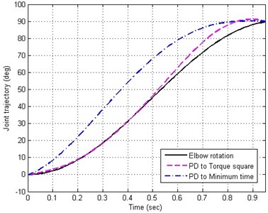
Fig. 4Joint angle prediction of an elbow rotation from 0 to 90 degrees
3. Results
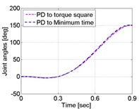
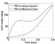
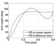
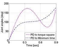
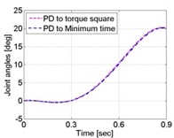
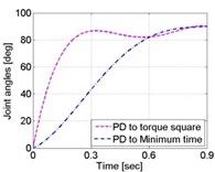
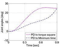
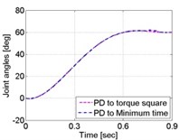
The inverse kinematic problem for an elbow movement performed in Opensim and the trajectories obtained with the solution of the PD problem when considering both the torque square and the minimum time as a cost function are shown in Fig. 4. Both solutions of the PD problem are close to the elbow trajectory given by Opensim. However, PD with minimum time as a cost function presented a larger mean squared error (MSE) with respect to the solution obtained when using squared toque as a cost function. Minimum time gave a mean error of 241.4879 and torque squared gave an error of 10.2932, meaning that considering the dynamic effort as a cost function to solve the optimization problem offered a closest approach to compute the elbow rotation from 0 to 90 degrees. Due to the proposed cost functions seem to provide good approaches to real trajectories, we solved the eight PD problems to find the joint trajectories of the exoskeleton considering both the minimum time and the torque square. The solutions were used as reference signals for each of the joint PID controllers of the exoskeleton during the simulations of motion. Joint 1 rotated from 0 to 20 degrees, Joint 2 rotated from 0 to 140 degrees, Joint 3 rotated from 0 to 90 degrees, Joint 4 rotated from 0 to 180 degrees, Joint 5 rotated from 0 to 150 degrees, Joint 6 rotated from 0 to 90 degrees, Joint 7 rotated from 0 to 25 degrees, Joint 8 rotated from 0 to 60 degrees. Fig. 5 show the joint trajectories measured in the joints of the exoskeleton. For the trajectories obtained considering minimum time Joint J1 had an MSE of 2.3732×10⁻⁸, J2 had an error of 5.5882×10⁻⁶, J3 had an error of 5.8373×10⁻⁶, J4 had an error of 2.5301×10⁻⁸, J5 had an error of 2.4282×10⁻⁷, J6 had an error of 6.4925×10⁻¹⁰, J7 had an error of 2.8127×10⁻¹¹, J8 had an error of 8.2132×10⁻¹⁷. For the trajectories obtained considering dynamic effort, joint J1 had an MSE of 2.2401×10⁻⁸, J2 had an error of 1.0740×10⁻⁵, J3 had an error of 9.2105×10⁻⁶, J4 had an error of 3.6846×10⁻⁹, J5 had an error of 2.3007×10⁻⁷, J6 had an error of 8.9500×10⁻¹¹, J7 had an error of 1.1083×10⁻¹¹, J8 had an error of 0.0667. According to the results obtained during the simulation of motion, based on the computation of the MSE for each joint of the exoskeleton, the system had a good response when moving the exoskeleton in the lower limits of the arm ROM. The mean of the MSE obtained when moving the exoskeleton using PD with minimum time as cost function was 1.463×10⁻⁶. The mean of the MSE obtained when moving the exoskeleton using PD with dynamic effort as cost function was 0.0083.
Joint J8 had the smallest MSE 8.2132×10⁻¹⁷ of when executing the trajectory obtained using PD with minimum time as cost function and J2 had the largest error of 5.5882×10⁻⁶. Joint J8 had the largest MSE of 0.0667 when considering the dynamic effort as a cost function and J6 had the smallest error of 8.9500×10⁻¹¹.
Fig. 5Joint trajectories of the 8 DOF of the exoskeleton when simulating its motion in the lower limits of the human arm ROM: a) joint 1 from 0 to 20 degrees, b) joint 2 from 0 to 140 degrees, c) joint 3 from 0 to 90 degrees, d) joint 4 from 0 to 180 degrees, e) joint 5 from 0 to 150 degrees, f) joint 6 from 0 to 90 degrees, g) joint 7 from 0 to 25 degrees, h) joint 8 from 0 to 60 degrees
a)
b)
c)
d)
e)
f)
g)
h)
4. Discussion
This work presents the design of an exoskeleton intended to be used in robot-mediated therapy for the upper limb in post-stroke patients. By taking advantage of the characteristics of Opensim to model a human arm, it was possible to design an exoskeleton that allows the movement of the anatomical center of rotation of each element of the human arm during locomotion. Solidworks served to design the structure of the exoskeleton and provided precise physical measurements such as lengths, masses, centers of mass and inertial data of each element of the structure that allowed the construction of a dynamic model of the exoskeleton in MATLAB, and a model for simulation of motion in developed in Simmechanics. The dynamic model helped to model the system as a predictive dynamics problem that was used to predict the motion of the elbow considering the torque square and the minimum execution time for the desired rotation as cost functions. The solution of the optimization problem was accurate when compared to the elbow rotation given by an arm model developed by Holzbaur and colleagues in Opensim. We computed the mean squared error to define which cost function gave the most accurate approach. The results showed that predictive dynamics with torque square as a cost function had a smaller mean squared error. The model of the arm implemented in Opensim only provides data for the motion of the elbow, we used predictive dynamics to predict several joint trajectories to simulate the rotation of the shoulder, the elbow and the wrist. Further work considers the implementation of a motion capture system to analyze the motion of the upper limb in the execution of the joint rotations simulated in this work, the analysis will show which cost function offers the best approach to the arm motion in the execution of specific joint rotations. The exoskeleton meets the kinematic characteristics of the human arm considering independent joint control, allowing full range of motion for the execution of repetitive exercises and motor tasks for supporting the rehabilitation of poststroke patients in comparison to other systems such as KINARM that only supports the rehabilitation of the elbow and shoulder in the horizontal plane; MAHI EXO-II whose 5 DOF permit the rehabilitation of elbow, forearm and wrist; and L-EXO that is designed to rehabilitate the shoulder and the elbow. Since co-simulation takes advantage of virtual tools that can be set up accordingly, it is possible to construct personalized devices according to the needs of each user. The modular design of the exoskeleton will allow its construction in 3D printers using polymers which would reduce the weight of the device for the user, favoring its wearability and portability. Since the exoskeleton is designed to work under independent joint control, the system will have the capability to be programmed for assistance algorithms similarly to the BONES exoskeleton, enabling it to work as passive, assistive and active-assistive mode. The proposed independent joint control is suitable to keep records of each joint movement during the execution of a desired exercise or motion task, as the exoskeletons KINARM, MAHI EXO-II and L-EXO do. This characteristic will help to keep track of the rehabilitation process and will allow the user to analyze properly the joint trajectories of the arm when moving in its ROM during the execution of specific tasks, such as picking up objects. This characteristic will also be helpful to analyze the accuracy of different joint trajectories computed using predictive dynamics in order to determine the pertinence of using when the exoskeleton is responsible for the locomotion of the arm in passive and active-assistive mode and to create a database to test future personalized exoskeletons. Future work includes the construction of the exoskeleton and the identification of friction for the validation of the dynamics model.
References
-
Cauraugh J., Light K., Kim S., Thigpen M., Behrman A. Chronic motor dysfunction after stroke. Stroke, Vol. 31, 2000, p. 1360-1364.
-
Byl N. N., Abrams G. M., Pitsch E., Fedulow I., Kim H., Simkins M., Nagarajan S., Rosen J. Chronic stroke survivors achieve comparable outcomes following virtual task specific training guided by a wearable robotic orthosis (UL-EXO7) and actual task specific repetitive training guided by a physical therapist. Journal of Hand Therapy, Vol. 26, 2013, p. 343-352.
-
Vloothuis J., Mulder M., Nijgland R. H. M., Konjunenbelt M., Mulder H., Hertogh C. M. P. M., van Tulder M., Kwakkel G., van Wegen E. Caregiver-mediated exercises with e-health support for early supported discharge after stroke (CARE4STROKE): study protocol for a randomized controlled trial. EMC Neurology, Vol. 15, 2015, p. 93.
-
Bower K. J., Louie J., Landesrocha Y., Speedy P., Gorelik A., Bernhardt J. Clinical feasibility of interactive motion-controlled games for stroke rehabilitation. Journal of Neuroengineering and Rehabilitation, Vol. 12, 2015, p. 63.
-
Sivan M., Gallagher J., Makower S., Keeling D., Bhakta B., O’Connor R. J., Levesley M. Home-based computer assisted arm rehabilitation (hCAAR) robotic device for upper limb exercise after stroke: results of a feasibility study in home setting. Journal of Neuroengineering and Rehabilitation, Vol. 11, 2014, p. 163.
-
Susanto E. A., Tong R. K. Y., Ockenfeld C., Ho N. S. K. Efficacy of robot assisted fingers training in chronic stroke survivors: a pilot randomized-controlled trial. Journal of Neuroengineering and Rehabilitation, Vol. 12, 2015, p. 42.
-
Thielbar K. O., Lord T. J., Fischer H. C., Lazzaro E. C., Barth K., Stoykov M. E., Triandafilou K. M., Kamper D. G. Training finger individuation with a mechatronic-virtual reality system lead to improved fine motor control post-stroke. Journal of Neuroengineering and Rehabilitation, Vol. 11, 2014, p. 171.
-
Fluet G. G., Merians A. S., Qiu Q., Davidow A., Adamovich S. V. Comparing integrated training of the hand and arm with isolate training of the same effectors in persons with stroke using haptically rendered virtual environments, a randomized clinical trial. Journal of Neuroengineering and Rehabilitation, Vol. 11, 2014, p. 126.
-
Brunner I., Skouen J. S., Hofstad H., Strand L. I., Becker F., Sanders A. M., Pallesen Kristensen H. T., Michielse M., Verheyden G. Virtual reality training for upper extremity in subacute stroke (VIRTUES): study protocol for a randomized controlled trial. BMC Neurology, Vol. 14, 2014, p. 186.
-
Volpe B. T., Krebs H. I., Hogan N., Edelsteinn L., Diels C. L., Aisen M. L. Robot training enhanced motor outcome in patients with stroke maintained over 3 years. Neurology, Vol. 53, 1999.
-
Basteris A., Nijenhuis S. M., Stienen A. H. A., Buurke J. H., Prange G. B., et al. Training modalities in robot-mediated upper limb rehabilitation in stroke: a framework for classification based on a systematic review. Journal of Neuroengineering and Rehabilitation, Vol. 11, 2014, p. 111.
-
Milot M. H., Spencer S. J., Chan V., Allington J. P., Klein J., Chou C., Bobrow J. E., Cramer S. C., Reinkensmeyer D. J. A crossover pilot study evaluating the functional outcomes of two different types of robotic movement training chronic stroke survivors using the arm exoskeleton BONES. Journal of Neuroengineering and Rehabilitation, Vol. 10, 2013, p. 112.
-
Otaka E., Otaka Y., Kasuga S., Nishimoto A., Yamazaki K., Kawakami M., Ushiba J., Liu M. Clinical usefulness and validity of robotic measures of reaching movements in hemiparetic stroke patients. Journal of Neuroengineering and Rehabilitation, Vol. 12, 2015.
-
Blank A., O’Malley M. K., Francisco G. E., Conreras-Vidal J. L. A pre-clinical framework for neural control of a therapeutic upper-limb exoskeleton. 6th International IEEE/EMBS Conference on Neural Engineering (NER), 2013, p. 1159-1162.
-
French J. A., Rose C. G., O’Malley M. K. System characterization of MAHI EXO-II: a robotic exoskeleton for upper extremity rehabilitation. Proceedings of ASME Dynamic Systems and Controls Conference, 2014.
-
Frisoli A., Salsedo F., Bergamasco M., Rossi B., Carboncini M. C. A force-feedback exoskeleton for upper-limb rehabilitation in virtual reality. Applied Bionics and Biomechanics, Vol. 6, 2009, p. 115-126.
-
Frisoli A., Procopio C., Chisari C., Creatini I., Bonfiglio L., Bermamasco M., Rossi B., Carboncini M. C. Positive effects of robotic exoskeleton training of upper limb reaching movements after stroke. Journal of Neuroengineering and Rehabilitation, Vol. 9, 2012, p. 36.
-
Nordin N., Xie S. Q., Waijnsche B. Assesment of movement quality in robot-assisted upper limb rehabilitation after stroke: a stroke. Journal of Neuroengineering and Rehabilitation, Vol. 11, 2014, p. 137.
-
Menychtas D., Carey S. L., Dubey R. Simulation algorithm for the upper limb for better training and prosthesis prescription for amputees. PETRA’15, Vol. 56, 2015, p. 1-6.
-
Sawers A., Ting L. H. Perspectives on human-human sensorimotor interactions for the design of rehabilitation robots. Journal of Neuroengineering and Rehabilitation, Vol. 11, 2014, p. 142.
-
Pons J. L. Rehabilitation exoskeletal robotics, the promise of an emerging field. IEEE Engineering in Medicine and Biology Magazine, Vol. 29, 2010, p. 57-63.
-
Wolff J., Parker C., Borisoff J., Mortenson W. B., Mattie J. A survey of stakeholder perspectives on exoskeleton technology. Journal of Neuroengineering and Rehabilitation, Vol. 11, 2014, p. 169.
-
Drake R. L., Vogl A. W., Mitchell A. W. M. Upper Limb. In Gray’s Anatomy for Students. Churchill Livingstone, Elsevier, Philadelphia, PA, United States, 2010, p. 650-664.
-
Holzbaur K. R. S., Murray W. M., Delp S. L. A model of the upper extremity for simulating musculoskeletal surgery and analyzing neuromuscular control. Annals of Biomedical Engineering, Vol. 33, 2005, p. 840.
-
Delp S. L., Anderson F. C., Arnold A. S., Loan P., Habib A., John C. T., Guendelman E., Thelen D. G. OpenSim: open-source software to create and analyze dynamic simulations of movement. IEEE Transactions on Biomedical Engineering, Vol. 54, 2007.
-
Siciliano B., Sciavico L., Villani L., Oriolo G. Robotics: Modelling, Planning and Control. Springer, London, 2009.
-
Abdel-Malek K. A., Arora J. S. Predictive Dynamics Human Motion Simulation. Academic Press Elsevier, Waltham MA, United States, 2013.
-
Xiang Y., Arora J. S., Abdel-Malek K. Hybrid predictive dynamics: a new approach to simulate human motion. Multibody System Dynamics, Vol. 28, 2012, p. 199-224.
-
Churchill E., Laubach L. L., Mcconville J. T., Tebbetts I. Anthropometric Source Book. Volume 1: Anthropometry for Designers. Webb Associates, NASA Reference Publications, Yellow 320 Springs, OH, United States, 1978.
-
Hortal E., Planelles D., Resquin F., Climent J. M., Azorin J. M., Pons J. L. Using a brain machine interface to control a hybrid upper limb exoskeleton during rehabilitation of patients with neurological conditions. Journal of Neuroengineering and Rehabilitation, Vol. 12, 2015, p. 92.
-
Yao J., Sheaff C., Dewald J. P. A. TUsage of the ACT3D Robot in a Brain Machine Interface for Hand Opening and Closing in Stroke Survivors. IEEE International Conference on Rehabilitation Robotics, 2008, p. 938-942.
-
Xiang Y., Chung H.-J., Kim J.-H., Bhatt R., Rahmatalla S., Yang J., Marler T., Arora J. S., Abdel-Malek K. Predictive dynamics: an optimization-based novel approach for human motion simulation. Structural and Multidisciplinary Optimization, Vol. 41, 2010, p. 465-479.
Cited by
About this article
This project was supported by FAI C08-FAI-10-31.67.
