Abstract
In recent years, frequent tower collapses have been mostly related to fatigue damage. Therefore, this paper systematically studies the fatigue resistance performance and reinforcement methods of tower foundation connection components through on-site tests and finite element analysis. The test analyzed the lifespan, stress-strain characteristics, crack development and mechanical properties of the connection components under fatigue loads; numerical simulation compared the fatigue life and safety of ordinary components, reinforced with steel mesh, C100 high-strength concrete components, and C40 and C100 composite components, etc., providing key basis for engineering reinforcement.
Highlights
- The field experiments and simulation experiments mutually validate each other.
- Finite element fatigue simulation.
- Consider various methods of reinforcing with basic connection pieces.
1. Introduction
In the foundation design of large-capacity wind turbines, special attention must be paid to structural stiffness and fatigue resistance, especially given the frequent tower collapses related to fatigue damage, as highlighted in fragility analyses of wind turbine towers [1]. Ding Zhaodong and Li Jie systematically categorized and discussed concrete fatigue research [2]. Shen summarized the development history, working principles, and advantages of multi-cavity steel tube concrete structures, noting their superior seismic performance and load-bearing capacity [3]. Liu et al. conducted a systematic experimental study on the performance of rubber concrete columns restrained by galvanized corrugated steel pipes under eccentric compression and cyclic loading [4]. Recent reviews on fatigue reliability further emphasize the importance of this topic for wind energy systems [5].
This study simulated long-term fatigue loads to uncover the deformation distribution law and concrete crack propagation mechanism in stud-connected structures, providing crucial data for optimizing the foundation design of steel tube concrete composite structures for wind turbine towers. Subsequently, finite element software was employed to simulate fatigue tests on concrete specimens at the tower-foundation connection, analyzing the influence of horizontal and vertical fatigue loads on the specimen’s mechanical properties. Finally, improvement measures for enhancing the fatigue resistance of the connection components were proposed.
2. Performance test and simulation of tower foundation connection components
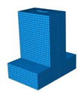
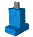
The construction of the insert-type column foot specimen with embedded columns and the reinforcement of the concrete platform are shown in Fig. 1. The embedment depth is 1/3 of the original length of the component. The steel used in the rectangular steel-concrete composite specimen is Q235, and the concrete is C30.
Using the MTS fatigue testing machine, a 55 kN sinusoidal pulse cyclic load was applied at a frequency of 1 Hz. The vertical tensile-compressive load was 450 KN and a total of 100,000 cycles were carried out. Before the test, a static cyclic loading was conducted first and data was collected. Subsequently, the machine was stopped at 10,000, 20,000, 50,000 and 100,000 fatigue cycles, and the static loading was gradually increased to the fatigue load value.
Fig. 1Tower cylinder foundation connection component model. Team member Wang Yiping took the photo on April 7, 2025 in Sichuan Architecture Vocational College, Deyang City, Sichuan Province, China
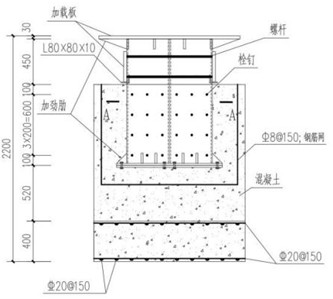
a) Design drawing
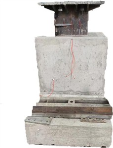
b) Laboratory prototype model
3. Analysis of test results
3.1. Test stress and strain data of tower foundation connection components
The differences in transverse and longitudinal strains under different fatigue loads are significant: the first 30,000 cycles are the pressure load stage, and the next 50,000 to 90,000 cycles are the tension load stage. Under pressure, the transverse strains of 23, 21, and 19 are the largest, followed by 18 and 16, with the rest being close to 0. This indicates that the steel components without embedded concrete have large transverse deformations, which decrease as the embedding depth increases, and there is almost no deformation at a depth of 400mm. Under tension, the longitudinal strains of 20, 18, and 24 are the largest, with the rest being close to 0. The unembedded parts have large longitudinal deformations, and there is almost no deformation at a depth of 100mm; 19 is located in the crossbeam, and the longitudinal deformation decreases significantly. At the nut position, the strain of No. 27 (deeply embedded) rose sharply to 280 μm, while that of No. 26 (lightly embedded) increased gradually to 70 μm. This indicates that the deeper the embedding, the greater the tensile strain of the bolt.
In terms of displacement: During the 0-30,000 pressure cycle stage, the vertical displacement of No. 29 (steel) was 4 mm, that of No. 30 (concrete) was 5 mm, and the lateral displacement of No. 31 was –1 mm; During the 3-90,000 tension cycle stage, the displacement of the steel remained stable at 10±0.5 mm, the concrete rebound was 5 mm, and the cumulative lateral displacement reached –10 mm.
Table 1Maximum lateral and longitudinal strain values under different fatigue loads
Transverse strain (×10-6) | Longitudinal strain (×10-6) | |
Pressure fatigue loading action | 240 | –300 |
Load of tension fatigue action | –270 | 750 |
3.2. Test crack data of tower foundation connection components
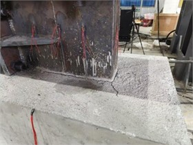
The left and right sides of the center seam form a long side, with the width being the width of the component. The cracks are stained with ink, and the greater the staining intensity, the wider (or thicker) the generated cracks. The ink staining experiment shows that the cracks are symmetrically distributed along the long side. The maximum staining depth in the left side of the center seam area reaches 10 cm, the maximum depth in the right side area is 11 cm, and a 10 cm deep continuous crack is formed at the center seam position. This verifies that there is a significant stress concentration phenomenon at the long side connection part of this component under load. After the external concrete of the connection piece cracks, it is prone to allow rainwater to seep in, causing rusting at the column foot. At the same time, the cracks will continue to expand with the increase of load, resulting in a decrease in stiffness and strength. Therefore, measures need to be taken for improvement. The damaged state is shown in Fig. 3. This picture was taken by team member Cao in Deyang, Sichuan Province, China.
Fig. 2Mean strain under different fatigue levels
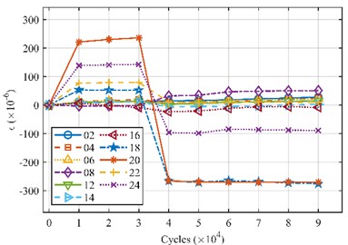
a) Transverse strain
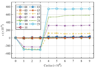
b) Longitudinal strain
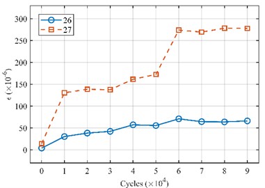
c) Bolt strain
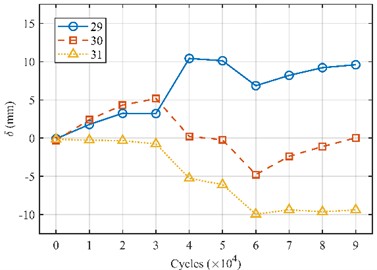
d) External displacement
4. Performance test and simulation of tower foundation connection components
4.1. Material parameter settings
This paper uses the finite element software to conduct fatigue test simulations on the concrete specimens of the tower tube and foundation connection. Firstly, the constitutions of steel and concrete are determined. Then, the corresponding finite element model is established. By analyzing the strain data, the depth and width of the failure cracks of the specimens, the mechanical properties of the tower tube and foundation connection concrete specimens under horizontal and vertical fatigue loads are studied. Finally, improvement measures for the connection components are proposed. The steel used for the rectangular steel-concrete composite specimens in this study is Q235. The concrete grade used for the rectangular steel-concrete test specimens in this paper is C30.
Fig. 3Crack depth and width at the tower-foundation connection
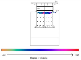
a) Connection component failure situation
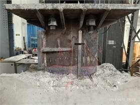
b) The actual damage condition of the connection
4.2. Finite element model establishment
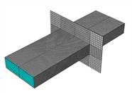
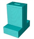
For the areas prone to cracking, three reinforcement schemes were proposed: Fig. 4(f) shows reinforced concrete with steel mesh (simulated by equivalent cross-sectional steel plates); Fig. 4(d) shows C100 ultra-high performance concrete (UHPC); Fig. 4(i) shows a combined structure of inner half C100 UHPC and outer half C40 concrete. The finite element models of steel tube concrete and concrete columns are shown in Fig. 4. These schemes align with recent studies on steel-concrete composite towers, which have demonstrated the effectiveness of similar material configurations in improving wind-induced response and fatigue reliability [6].
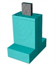
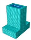
Fig. 4Finite element models of the concrete-filled steel tube specimen and the concrete column
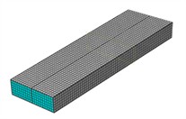
a) Steel tube concrete specimen
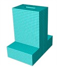
b) External concrete column
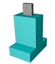
c) Overall specimen
d) C100 concrete column
e) The overall specimen after external application of C100 concrete
f) Steel-reinforced concrete specimens with steel mesh reinforcement
g) Steel tube concrete columns reinforced with steel mesh
h) The overall specimen reinforced with steel mesh
i) Concrete columns using a combination of C100 and C40 materials
j) The overall test specimens after external application of C100 and C40 concrete
In the model, the steel plates, steel mesh and concrete all adopt C3D8R solid elements, and are divided using structured grid technology. Through the sensitivity analysis of grid size, the sizes of the core concrete and steel pipe mesh were finally determined to be 10 mm, and the external concrete to be 50 mm.
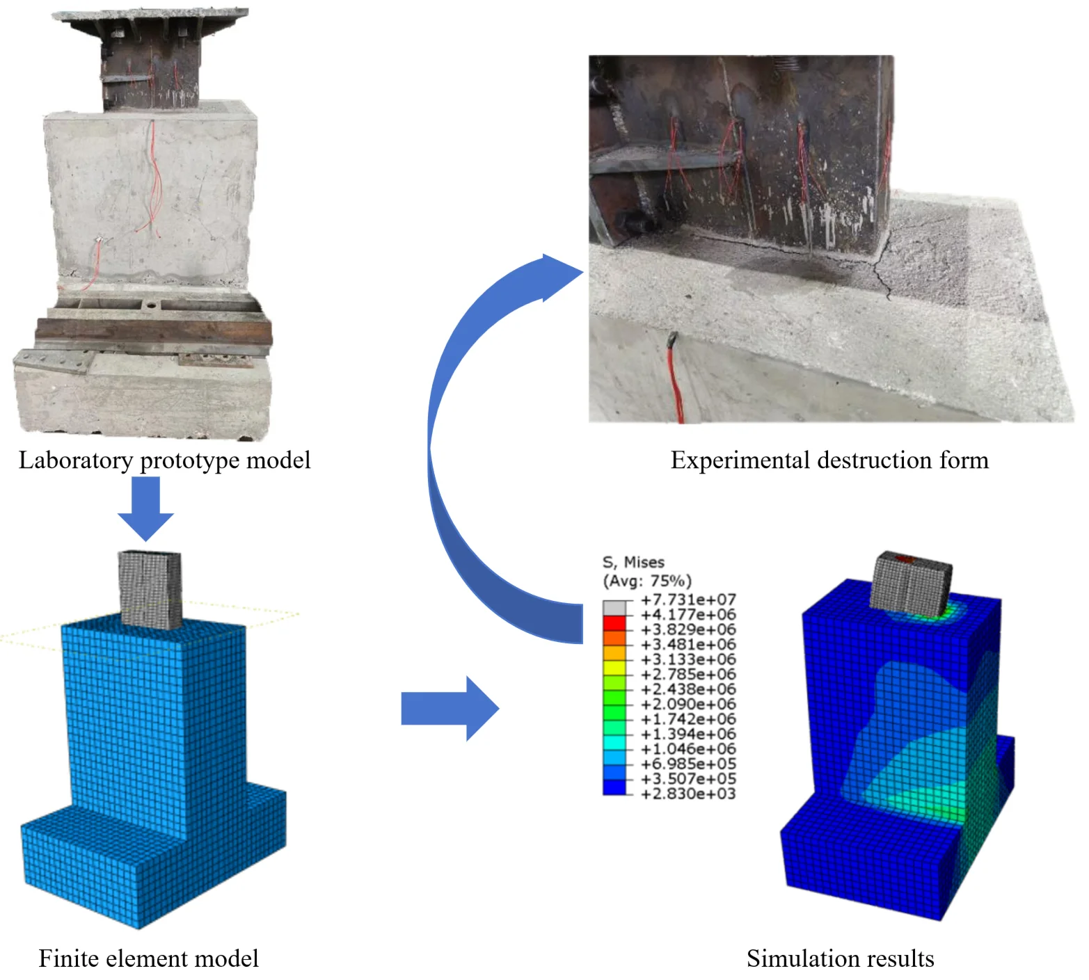
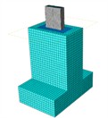
By comparing the simulation results of the column foot connection components with the actual failure situation of the test, as shown in Fig. 5(b), the accuracy of the finite element model was verified. The simulation results were in good agreement with the test results, indicating that the model is reliable and can be used for subsequent research.
Fig. 5Comparison of failure modes between the simulated and experimental specimens. Team member Wang Yiping took this photo on April 7, 2025 in Sichuan Architecture Vocational College, Deyang City, Sichuan Province, China
a) Simulation results
b) Experimental destruction form
4.3. Fatigue life simulation results
Based on the results of the single-cycle simulation in Abaqus, the FE-SAFE software was used to calculate the fatigue life of the specimen. Fig. 6 shows the fatigue life curve of the specimen. The abscissa and ordinate are the number of fatigue cycles and the logarithmic values of the corresponding loads (N), respectively. As the load increases, the fatigue life of all schemes decreases. Among them, the scheme with steel mesh has the lowest fatigue life, while the curves of the ordinary, C100 and C40+C100 schemes always overlap significantly.
Fig. 6Fatigue life curve of the simulated specimen
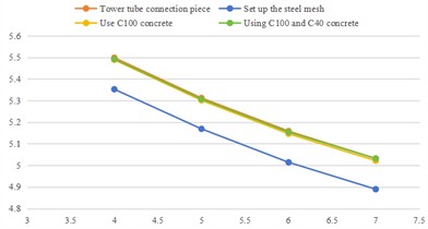
a) Horizontal thrust fatigue life curve
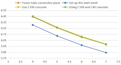
b) Vertical pressure fatigue life curve
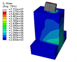
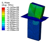
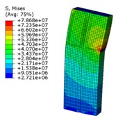
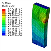
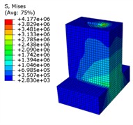
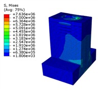
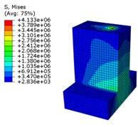
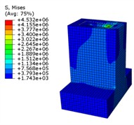
Fig. 7Deformation contour plot of the simulated specimen
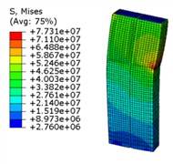
a) Stress map of the steel tube concrete connection component
b) Stress map of reinforced steel mesh-attached connection component of steel fiber reinforced concrete
c) Stress cloud diagrams of the specimens using C100 concrete
d) Stress maps of the C40 and C100 specimens
From the stress maps (Fig. 8), it can be seen that the interface of the ordinary connection piece presents a stepped high-stress zone, prone to shear slip; the weld points of the steel mesh scheme have significant stress concentration (1.48 times that of the ordinary piece), with a high risk of brittle fracture; the C100 scheme has a relatively uniform stress distribution, demonstrating the advantage of resisting compression; the C40 and C100 combined scheme has the most uniform stress distribution, with the lowest peak value and no sudden change, and has the best safety. In terms of fatigue life, failure is mainly caused by interface slip; the steel mesh scheme further reduces by 4.2 %; the C100 scheme has good fatigue resistance but is more costly; the C40 + C100 combination has the best overall performance and is the recommended configuration.
Fig. 8Stress contour plot of the components of the column base connector and its reinforced specimen
a) Concrete column stress map
b) Stress map of reinforced concrete columns with steel mesh
c) Stress map of the concrete column using C100 material
d) Using the stress maps of C40 and C100 concrete columns
5. Conclusions
1) This paper conducts fatigue tests on the steel tube concrete composite structure with bolted insert-type foundation, revealing the deformation patterns of the connection components and the mechanism of concrete crack expansion. It analyzes the stress, strain and crack development of this structure under cyclic loading, and determines that the vulnerable location is at the connection between the steel tube concrete specimen and the external concrete.
2) The finite element verification and comparison show that the combination of C40 and C100 concrete schemes exhibits the best performance in terms of stress distribution uniformity, fatigue life and safety, significantly outperforming ordinary connection components, reinforced mesh and the single C100 concrete scheme.
It is recommended that in engineering projects, the combination of C40 and high-strength concrete above C60 should be prioritized to reduce costs and enhance the performance and durability of the connection components.
References
-
A. Quilligan, A. O. ’Connor, and V. Pakrashi, “Fragility analysis of steel and concrete wind turbine towers,” Engineering Structures, Vol. 36, pp. 270–282, Mar. 2012, https://doi.org/10.1016/j.engstruct.2011.12.013
-
Z. Ding and J. Li, “Review of the analysis methods of fatigue of concrete,” Mechanics in Engineering, Vol. 37, No. 1, pp. 40–48, 2015, https://doi.org/10.6052/1000-0879-14-167
-
L. Shen et al., “Experimental study on axial compression behavior of short ultra-high performance concrete-filled multi-cell middle-long hollow sandwich steel tubular columns,” (in Chinese), Journal of Building Structures, Vol. 42, pp. 204–211, 2021, https://doi.org/10.14006/j.jzjgxb.2021.s2.0024
-
L. Zhang, B. Liu, M. Feng, H. Sun, and C. Hao, “Experimental investigation on the compression-bending performance of rubberized concrete columns confined by galvanized corrugated steel tubes,” Structures, Vol. 69, p. 107301, Nov. 2024, https://doi.org/10.1016/j.istruc.2024.107301
-
D. Liao, S.-P. Zhu, J. A. F. O. Correia, A. M. P. de Jesus, M. Veljkovic, and F. Berto, “Fatigue reliability of wind turbines: historical perspectives, recent developments and future prospects,” Renewable Energy, Vol. 200, pp. 724–742, Nov. 2022, https://doi.org/10.1016/j.renene.2022.09.093
-
M. Zhang, B. Liu, C. Gao, M. N. Hossain, and G. Zhao, “Wind-induced response analysis and fatigue reliability study of a steel-concrete composite wind turbine tower,” Buildings, Vol. 14, No. 6, p. 1740, Jun. 2024, https://doi.org/10.3390/buildings14061740
About this article

The authors have not disclosed any funding.
The datasets generated during and/or analyzed during the current study are available from the corresponding author on reasonable request.
The authors declare that they have no conflict of interest.
