Abstract
An experimental verification of the effectiveness of applying a compromise fuel injection advance angle (FIAA) was conducted on a test stand for a PD1M type diesel generator unit. The study included an analysis of injection pressure changes at various FIAA values, as well as tests of the installation with the ESUVT.01 electronic fuel injection control system under load. Additionally, modeling of the diesel engine’s working process was performed using the “Diesel-RK” software package, followed by processing of the obtained data. Comparison of test results in locomotive characteristic modes at fuel injection advance angles of 14° and 29° crankshaft rotation showed that using a compromise FIAA value ensures a reduction in the locomotive’s average operational fuel consumption by 7-10 %, depending on operating conditions. Furthermore, decreasing the advance angle positively affects the reduction of maximum cylinder pressure and exhaust gas temperature, indicating an increase in the overall effectiveness of this approach.
Highlights
- The possibility of reducing fuel consumption in shunting diesel locomotives during operation by decreasing the fuel injection advance angle in D50 type diesel engines (PD1M, 1-PD4D) with mechanical fuel delivery control has been theoretically substantiated and experimentally confirmed.
- Reducing the fuel injection advance angle to 14° instead of the nominal 29° in the PD1M (1-PD4D) diesel engine with mechanical control results in fuel savings of 6.9-15% for TEM2 (TEM18) shunting locomotives, depending on operating conditions.
- This effect is achieved when the power output of the locomotive's power plant is limited to 75% of its full capacity.
- Operating these locomotives at high throttle positions with a reduced fuel injection angle (14 degrees) leads to an increase in exhaust gas temperature above critical values (510°C).
1. Introduction
Studies on the operational modes of shunting locomotives have revealed that a significant portion of locomotive operating time is spent in idle and low-load modes of the power plant (up to 80 % or more). A substantial part of the work performed occurs at low positions of the driver’s controller (up to 40 %), and the amount of diesel fuel consumed in these modes accounts for up to 50 % in the power plant’s idle mode [1], [2]. Analysis of operating modes for shunting locomotives working in industrial transport conditions shows similar patterns [3], [4].
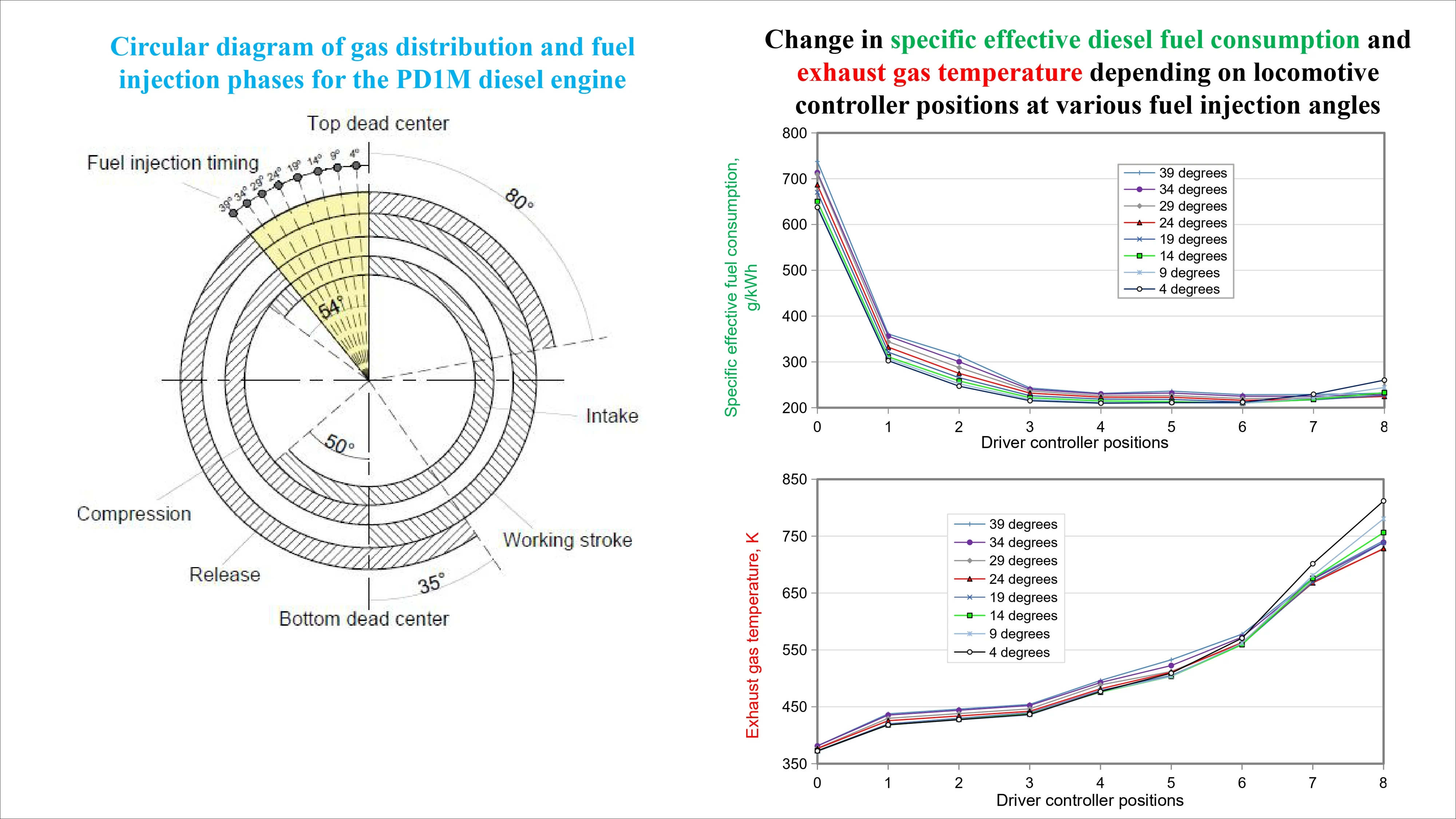
When developing locomotives, the parameters of design solutions and settings for all units are calculated to ensure optimal operation in nominal mode, corresponding to the diesel engine’s maximum power. A similar mode is used for post-repair tests, including rheostat checks. Operational and technical documents [5] regulate key power plant indicators such as generator power, maximum cylinder pressure, and exhaust gas temperature. If necessary, these indicators are adjusted by changing the cyclic fuel supply and fuel injection timing for individual cylinders.
A contradiction arises between the requirements for installation parameters at the design stage and their actual provision during operation under various locomotive life cycle conditions.
One approach to solving this problem is the implementation of electronic control systems that regulate the fuel supply and gas exchange process in diesel engines [6], [7]. Such systems allow for the optimization of gas distribution and fuel supply phases depending on the engines current operating modes, which contributes to increased efficiency. For example, modern fuel supply control systems [6] enable individual selection of optimal fuel injection timing for various engine operating modes, allowing for a 7-10 % reduction in average fuel consumption [8]-[10]. In the future, significant performance improvements can be achieved through the integration of electronic control of gas distribution phases and turbocharger nozzle assemblies [11], [12].
Previously, through mathematical modeling of the operating processes of PD1M and 1PD4D diesel engines, the potential for improving fuel efficiency in TEM2 and TEM18 series shunting locomotives with mechanical fuel supply control systems was theoretically substantiated. This was achieved by applying compromise values of fuel injection timing, aimed at reducing fuel consumption in idle and low-load modes by allowing a permissible increase in consumption at nominal mode [3]. Reducing the fuel injection timing from 29° to 14° of crankshaft rotation showed a 7-9 % decrease in average fuel consumption and a 12-15 % decrease in peak cylinder pressures while maintaining thermal loads within acceptable limits [13], [14].
Additionally, to confirm the obtained theoretical results, an experimental assessment of the influence of fuel injection timing on efficiency indicators and operating parameters of the 1PD4D diesel engine [4], installed on the TEM18DM locomotive, was conducted. The research was performed on an engine equipped with the ESUVT.01 electronic fuel supply control system.
The present study aims to experimentally verify the specified calculated conclusions on the PD1M diesel-generator unit.
2. Methodology
To conduct experimental studies, it was necessary to accurately determine the fuel consumption in kilograms per unit of work performed by the diesel generator set. The volumetric method for measuring fuel consumption proved unsuitable due to the high margin of error of the graduated instruments and the volumetric expansion of fuel as its temperature increased. Moreover, to conserve diesel fuel, studies were conducted within limited time intervals at steady-state modes according to the locomotive’s performance characteristics. Consequently, all calculations had to be performed electronically.
To meet the aforementioned requirements, a device for analyzing diesel locomotive fuel consumption electronically has been developed and manufactured. The device allows for the simultaneous analysis of fuel consumption and the work performed by the generator over a period of time in electronic form.
The value of specific fuel consumption per unit of work performed (kg/kW·h) was determined using Eq. (1):
where, – is the number of measurement cycles; – is the amount of fuel consumed during the calculation cycle, kg; – is the volume of work performed by the generator during the calculation cycle, kWh.
For the first position of the driver’s controller, the engine’s economic characteristic was characterized by the hourly fuel consumption (kg/hour), which is determined by Eq. (2):
where – is the specified duration of measurement time, s.
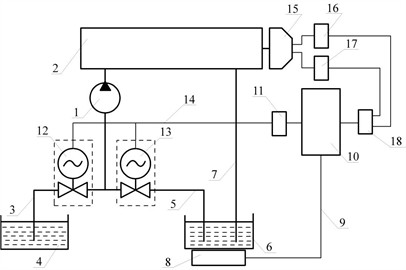
The functional diagram of the device for measuring diesel locomotive fuel consumption is shown in Fig. 1.
Fig. 1A manufactured device for measuring fuel consumption by an internal combustion engine: 1 – fuel supply pump; 2 – diesel engine; 3 – fuel tank; 4 – measuring tank; 5 – electronic scales; 6 – computer (recording device); 7 – relay converter; 8 – three-way electronic valve for fuel intake from the tank; 9 – three-way electronic valve for fuel intake from the measuring tank; 10 – traction generator; 11 – voltage sensor; 12 – current sensor; 13 – analog-to-digital converter (ADC)
3. Results and discussion
The study was conducted on the PD1M diesel generator unit in the diesel locomotive laboratory of the Saint Petersburg State University of Railway Transport for the nominal values of the fuel injection angle of the ESUVT.01 system and for fixed fuel injection angles of 29 and 14 degrees across the entire range of the diesel locomotive performance characteristics.
The experimental results of the change in the value of the specific fuel consumption per kWh of generator operation are presented in Table 1 and Fig. 2.
Table 1Experimental values of changes in the specific fuel consumption of the generator
Train driver’s control position | Electronic fuel injection management system | Fuel injection angle: 29 degrees | Fuel injection angle: 14 degrees | Comparison between 29 and 14 degrees % |
0 | 6,872 | 8,401 | 6,596 | –27,4 |
1 | 446,000 | 507,167 | 478,333 | –6,0 |
2 | 360,834 | 402,584 | 386,000 | –4,3 |
3 | 321,667 | 338,000 | 330,667 | –2,2 |
4 | 307,084 | 315,750 | 313,167 | –0,8 |
5 | 300,500 | 303,500 | 302,667 | –0,3 |
6 | 304,750 | 305,584 | 310,937 | 1,7 |
7 | 309,000 | 307,667 | 325,206 | 5,4 |
8 | 317,500 | 311,834 | 343,745 | 9,3 |
Fig. 2Change in the specific effective fuel consumption of the generator according to its load characteristic
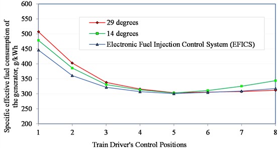
For comparison and analysis of changes in the diesel engine’s technical and economic parameters, the experiment was also conducted using the standard values of the electronic injection system’s fuel injection advance angle. Data processing was carried out using the InjectService v1.02 lite program.
From Table 1 and Fig. 2, it can be seen that when a diesel engine operates with a fuel injection angle of 14 degrees, the specific fuel consumption decreases up to approximately the 5th-6th positions of the locomotive engineer’s controller. Above the 6th position of the locomotive engineer’s controller, it increases again.
The values of exhaust gas temperature and maximum cycle pressure Pz (flash), which determine the reliability of diesel engine operation, changed according to the dependence of the calculated results. Figs. 3 and 4 show the experimental values for changes in Pz and exhaust gas temperature.
Fig. 3Change in the maximum cycle pressure value along the load characteristic of the locomotive
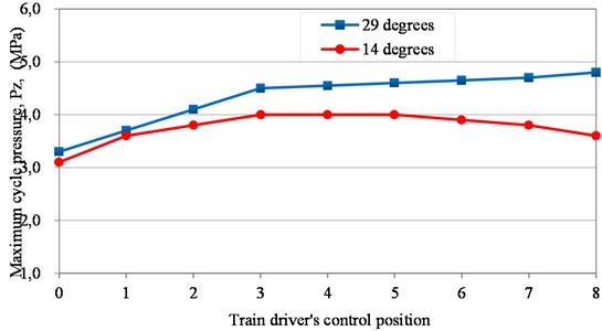
Reducing the peak cylinder pressure while simultaneously improving the fuel efficiency characteristics of the diesel engine contributes to a decrease in vibration levels. As a result, more favorable conditions are created for the functioning of all locomotive systems, increasing their longevity and operational reliability.
Fig. 4Change in the exhaust gas temperature of a diesel engine along the load characteristic
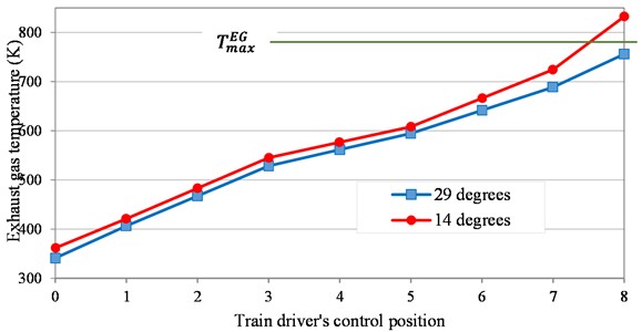
As shown in Figs. 5 and 6, reducing the fuel injection angle by 14 degrees leads to a decrease in the maximum cycle pressure, which contributes to lower mechanical stress and improved reliability of the diesel engine’s cylinder-piston group. When operating the diesel engine with a reduced angle value, the exhaust gas temperature slightly exceeds the limit value [5] by no more than 50 °C at the high positions of the driver’s controller, which aligns with the calculated data.
Analysis of the calculated and experimental results revealed that the average diesel fuel consumption of a locomotive per shift (12 hours) varies depending on the operating mode of the shunting locomotive. The results of this analysis for shunting locomotives operating under general railway conditions are presented in Table 2.
Calculated data refers to data obtained through computational methods [3] using the mathematical model of the PD1M diesel engine on the integrated “Diesel-RK” program.
The data from the laboratory stand were obtained during experiments on the PD1M diesel generator unit.
Experimental data on the TEM18DM diesel locomotive are the results of rheostat tests conducted on this locomotive equipped with an electronic fuel supply control system [4].
Table 2Generalized results of the average shift diesel fuel consumption for shunting locomotives operating on common railway networks
Calculated data Diesel-RK | Experiment on a laboratory bench | Experiment on the TEM18DM diesel locomotive | |
29 degrees | 150,28 | 181,61 | 156,6 |
14 degrees | 139,3 | 169,22 | 145,74 |
Comparison | 7,31% | 6,82 % | 6,93 % |
From the presented results, the following conclusions can be drawn:
When a diesel locomotive is operated on general-purpose railways, the average fuel savings per shift amounts to 7.1 %. At the same time, the main parameters determining the reliability of the cylinder-piston group operation either decrease or do not exceed the maximum permissible values [3].
4. Conclusions
1) The possibility of reducing operational fuel consumption in shunting diesel locomotives through optimization of the fuel injection advance angle in PD1M type diesel engines equipped with a mechanical fuel supply system has been theoretically substantiated and experimentally confirmed.
2) Theoretical studies conducted on a model demonstrated that setting the fuel injection advance angle to 14° of crankshaft rotation instead of the nominal value of 29° in a PD1M (1-PD4D) type diesel engine with mechanical fuel delivery control results in a 7.31 % reduction in average operational fuel consumption for TEM2 (TEM18) series shunting locomotives. Experimental research confirmed fuel savings of 6.82 %, varying based on locomotive operating modes, when the power plant output was limited to 75 % of maximum capacity.
3) Reducing the maximum cycle pressure in the cylinders contributes to decreasing vibrational loads on the engine and, consequently, leads to a reduction in overall noise levels, creating more favorable conditions for the operation of the locomotive as a whole.
References
-
V. O. Noskov, L. V. Milyutina, and I. S. Sinyov, “Study of conditions and operating modes of shunting locomotives,” Young Scientist: An International Scientific Journal, Vol. 1, No. 12, pp. 72–74, 2017.
-
V. Grachev, A. Grischenko, F. Bazilevskiy, and D. Kurilkin, “Impact of transition processes in propulsion of shunting diesel locomotive on fuel consumption in exploitation,” Bulletin of scientific research results, No. 1, pp. 48–67, Mar. 2022, https://doi.org/10.20295/2223-9987-2022-1-48-67
-
V. V. Grachev, V. V. Furman, O. R. Khamidov, and B. T. Kulmanov, “Improving operational fuel efficiency of a shunting locomotive by optimizing the diesel engine adjustment parameters,” Engines Construction, No. 2, pp. 18–30, 2024.
-
V. V. Grachev, V. V. Furman, O. R. Khamidov, and B. T. Kulmanov, “Efficiency experimental testing of the compromise adjustment parameters being introduced in the diesel-locomotive shunter engine,” Engines Construction, No. 3, pp. 3–13, 2024.
-
“Guidelines for major overhaul of the connecting rod-piston assembly in D50 type diesel engines part,” RK 103.11.422-2006, 2006.
-
“Electronic fuel supply control system ESUVT.01: ESUVT.01.00.000 OM operation manual,” 2012, https://www.zinref.ru/000_uchebniki/05300_transport_jd_teplovozi/019_ehsuvt-rukovodstvo-po-ehkspluatacii/003.htm?ysclid=mfi0xue7ep298274619.
-
“The free valve technology by Cargine,” https://www.car-engineer.com/the-free-valve-technology-of-cargine.
-
V. A. Markov, V. V. Furman, and V. A. Mironov, “Experimental studies of the electronic fuel injection control system for diesel locomotive engines,” Proceedings of Higher Educational Institutions, Mechanical Engineering, No. 1, pp. 38–48, 2012.
-
V. N. Igin, V. A. Markov, and V. V. Furman, “Performance tests of a diesel locomotive with electronic throttle control,” Proceedings of Higher Educational Institutions, Маchine Building, No. 76, pp. 25–37, Apr. 2014, https://doi.org/10.18698/0536-1044-2014-4-25-37
-
B. Kulmanov, O. Khamidov, U. Abdulatipov, B. Erkinov, and Z. Keldibekov, “Assessment of efficiency of diesel locomotive engines using controlled drives of gas distribution mechanisms,” in The 3rd International Symposium on Civil, Environmental, and Infrastructure Engineering (ISCEIE) 2024, Vol. 3317, No. 1, p. 060003, Jan. 2025, https://doi.org/10.1063/5.0266933
-
O. Ablyalimov, “To the substantiation of charge air parameters on different operating modes of diesel engines of diesel locomotives,” in E3S Web of Conferences, Vol. 460, p. 06010, Dec. 2023, https://doi.org/10.1051/e3sconf/202346006010
-
S. Jamilov, U. Safarov, N. Julenev, and K. Qosimov, “Analysis of experimental studies of transient processes during the start-up of the protection of the diesel generator set,” in International Conference on Thermal Engineering, 2024.
-
O. Ablyalimov, “Towards a methodology for optimizing indicator indicators of the working process of diesel locomotive diesel engines,” in E3S Web of Conferences, Vol. 621, p. 03005, Mar. 2025, https://doi.org/10.1051/e3sconf/202562103005
-
O. Ablyalimov, A. Avdeyeva, and D. Insapov, “Towards the efficiency transportation work of locomotives diesel traction in real operating conditions,” in E3S Web of Conferences, Vol. 508, p. 08004, Apr. 2024, https://doi.org/10.1051/e3sconf/202450808004
About this article

The authors have not disclosed any funding.
The datasets generated during and/or analyzed during the current study are available from the corresponding author on reasonable request.
The authors declare that they have no conflict of interest.
