Abstract
The article presents the results of the development and improvement of the theoretical foundations of mathematical modeling of controlled vibration mechanisms of the following three types: a scanner, a reversible mechanism, and mechanisms based on external physical fields – the electrorheological and magnetorheological effects. An analysis and generalization of existing studies and designs of vibration systems with controlled parameters and kinematic relations are carried out, and an updated classification of control methods is proposed. A unified mathematical model is formulated based on the principles of precision vibromechanics and modern vibration theory. Numerical calculations and qualitative analysis of the differential equations were performed using modern computational methods. The reliability of the results is confirmed by experimental tests of a new vibration mechanism design, demonstrating improved dynamic accuracy and control efficiency.

Highlights
- A unified mathematical model was developed and validated for four types of controlled vibration mechanisms — a positioning device, a reversible drive, an optical scanner, and an electrorheological mechanism — based on the principles of precision vibromechanics and vibration theory
- Application of the electrorheological effect for direct control of coupling forces increased dynamic accuracy by 10–15% and improved control efficiency by 1.3–1.5 times compared to classical models, while substantially reducing wear of contact surfaces
- A novel "integration over time intervals" method was proposed to obtain analytical solutions of nonlinear differential equations containing the sign function, addressing a problem with no existing general solution in the scientific literature
- Experimental prototypes of a reversible friction drive and a three-degree-of-freedom optical scanning device were built and tested, confirming superior dynamic accuracy, stability, and control efficiency over existing vibromechanical solutions
1. Introduction
The first studies of mechanisms and mechanical systems with variable and controllable parameters began in the 1970s and are associated with the works of K. V. Frolov, K. M. Ragulskis, R. Yu. Bansyavichyus, I. I. Blekhman, I. I. Vulfson, V. L. Veits, R.F.Nagaev, M. Bergstrasser, M. French, O. Kiyoshi, N. Adelman, I. Yokoyama, Kh. Kh. Usmankhodzhaev, R. I. Karimov, Sh. P. Alimukhamedov, K. A. Karimov, A. Kh. Umurzakov, A. Kh. Akhmedov and others [1-5]. In these works, the principles of precision vibromechanics were widely applied to control parameters – such as regulating frictional characteristics, employing high-frequency elastic vibrations, microvibrations, as well as external physical fields and noncircular wheels.
Despite significant achievements, classical mechanism and machine theory to date has not sufficiently encompassed fundamental research on the development of theoretical foundations for controlled mechanisms, taking into account technological processes and the specific features of interactions between links with higher and lower kinematic pairs. Moreover, in global practice, the results of theoretical studies rarely lead to the creation of next-generation designs based on modern innovative technologies.
Modern mechanical engineering requires continuous improvement and the creation of competitive, import-substituting products, which presupposes in-depth fundamental and applied research. One of the priorities is the development of the theoretical foundations of mechanisms with controllable parameters and linkages, as well as the design of a new generation of structures.
To create new-generation frictional and vibration mechanisms, it is necessary to comprehensively study their planar and spatial motions, construct mathematical models of the motion of working elements, and obtain both analytical and numerical solutions of the corresponding differential equations. The qualitative analysis of the obtained solutions and their rational application under conditions of high technical and technological requirements are among the key objectives of fundamental research.
The equations describing the motion of actuating links in controlled mechanisms are generally nonlinear and do not admit general analytical integration. A promising direction is the use of the electrorheological effect, which is based on the change in viscosity of an electrorheological suspension under the action of an electric field of constant or alternating voltage. Similarly, magnetorheological effects make it possible to sharply change the viscosity, elasticity, and plasticity of a medium under the action of a magnetic field [6-9]: with increasing magnetization frequency, the viscosity of the magnetic suspension decreases significantly. These phenomena open up opportunities for direct control of heat and mass transfer, hydrodynamic, electrical, and magnetic characteristics of the working medium by means of electrical signals.
2. Materials and methods
The International Federation for the Theory of Machines and Mechanisms (IFToMM), beginning with the 13th World Congress (Guanajuato, Mexico, 2009) and subsequent Executive Council meetings, designated research on controlled mechanisms as one of the priority areas in the theory of machines and mechanisms (TMM). In line with this, theoretical studies aimed at the development and improvement of mechanisms with controllable parameters and linkages have acquired particular significance [10].
The study was carried out with extensive use of the principles of precision vibromechanics, classical methods of TMM, vibration theory, and the fundamental principles of theoretical and applied mechanics. Modern programming methods on electronic computing machines were applied for numerical calculations. The basis for this work was the authors’ results on the development of the theory of frictional and vibrational mechanisms with controllable parameters [11-14].
Frictional and vibrational mechanisms find wide application in mechanical engineering and instrumentation, where increasing demands are placed on the accuracy and controllability of working elements, taking technological processes into account. A classification was developed, and methods for controlling parameters and linkages in frictionally engaged kinematic pairs were proposed, forming the foundation for subsequent theoretical studies and the design of new structures.
Special attention is devoted to the development of a friction mechanism that transforms the rotational motion of the driving shaft into the reciprocating motion of a movable element, with the capability of reversal without changing the direction of shaft rotation. The design includes: a driving shaft connected to a generator and a piezoelectric transducer; a movable element divided into two symmetrical parts equipped with elastic components for constant contact with the shaft; a position sensor connected to a roller guiding device; and piezoceramic plates that generate high-frequency bending microvibrations.
The operating principle is based on controlling friction forces in the contact zone (Fig. 1). The driving shaft rotates at a constant angular velocity ω. When a high-frequency signal is applied to the piezo plates, a local reduction in friction force occurs. The control unit, analyzing sensor data, adjusts the amplitude or frequency of the signal, creating a difference in friction forces and ensuring translational or reversible motion of the movable element along the x-axis. For automatic reciprocating motion, an electric regulator can be used to alternately switch the power supply of the piezo plates.
The use of the electrorheological effect makes it possible to control the viscosity of the working medium in an electric field and additionally reduce wear of the contact surfaces, thereby increasing reliability and positioning accuracy. The developed mechanism can be considered as a new class of vibration motors with a controllable contact zone. Potential applications include actuators for magnetic heads in data storage devices, high-speed electromechanical instruments, and systems requiring precision conversion of rotational motion into reciprocating motion.
The general view of the developed reversible mechanism is shown in Fig. 1. In the new design, the shortcomings mentioned above have been eliminated, and the reliability of the mechanism has been improved [10].
Fig. 1Diagram of a reversible mechanism converting rotational motion into translational motion
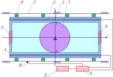
The created friction mechanism includes the following main elements: 1 – driving shaft, rotating around its own axis and connected to the movable element 2; 2 – movable element, equipped with elastic elements 5 and 6; 3, 4 – piezoelectric vibration transducers connected to generator 8 and control unit 9; 7 – guiding device with roller 11; 10 – sensor that detects the position of movable element 2.
The movable element, made of a hard material (for example, steel), moves along the -axis due to the friction forces arising at the contact points. To control the friction forces on the contact surface, plate-type piezoceramic vibration transducers are installed. The movable element is divided into two parts, which can move relative to each other along the vertical -axis, ensuring constant contact with the driving shaft. To maintain this contact, elastic components such as springs are used.
The operating principle of the mechanism is as follows: the driving shaft rotates at a constant angular velocity ω. At the contact points A and B, due to the compression of the elastic elements, friction forces of equal magnitude and opposite direction arise. The piezoceramic plates receive a high-frequency electrical signal from the generator through the control unit, which is converted into high-frequency bending vibrations. The subsequent mode and nature of motion are similar to the previous version of the mechanism.
The proposed friction drive provides the generation and regulation of the required motion laws of the driving and driven links by employing vertically oriented elastic uniaxial ultrasonic vibrations in the plane of frictional contact.
Mathematical models of this mechanism will be presented in the next section of the article.
Based on the principle of separating forces and control functions in higher kinematic pairs, and taking into account technological requirements, an optical scanning device has been developed for the precision deflection of a mirror. This device is designed for high-accuracy spatial angular positioning of optical elements in various optomechanical instruments and scanning systems. A distinctive feature of designs with a class-III (spherical) kinematic pair is the application of precision vibromechanics principles. In particular, one such principle involves the excitation and controlled direction of high-frequency elastic oscillations using piezoelectric transducers. This makes it possible to achieve controllable multidimensional angular deflection of the scanning mirror, for example, in laser target-designation systems for artillery or in controlled antennas of aircraft.
In the developed device, the drive is implemented as a rotor with a dynamic imbalance, rotating at an angular velocity . The design of the scanning unit includes (Fig. 2): 1 – mirror; 2 – spherical mirror holder; 3 – piezoelectric transducer; 4 – housing; 5 – dynamic imbalance; 6 – imbalance rotation angle sensor; 7 – power supply unit; 8 – control unit.
When high-frequency elastic vibrations are excited in the spherical vibrotransducer, the mirror together with the holder, under the action of the dynamic imbalance force, rotates around an axis passing through the origin of coordinates. The duration and phase of excitation, defined relative to the torque vector, determine the instantaneous position of the mirror’s rotation axis in space and its angular velocity, i.e., they allow the control system to precisely specify the angular velocity vector of the mirror. Thus, by regulating the friction force between the piezoceramic transducer and the spherical holder, it is possible to ensure the required controlled spatial positioning of the mirror.
Fig. 2Diagram of the optical scanning device
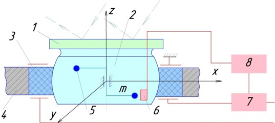
The main technical characteristics of the developed device are as follows: number of degrees of mobility – 3; maximum mirror mass – up to 10 kg; angular rotation speed along each coordinate – 2 rad/s; surface roughness coefficient – 0,005 (allowable limit value – 5×10⁻⁷ rad; maximum radial acceleration – 1.2×10³ rad/s2; mirror diameter – not less than 115 mm.
The drawback of the basic design is its limited load capacity: an increase in the mirror mass reduces its angular velocity. Improving the load-bearing capacity of the precision scanning device requires detailed dynamic studies of the mirror fixed on the spherical holder, taking into account the calculation of dynamic parameters and factors. On this basis, the design can be improved.
The improved version is a multidimensional laser deflector designed for spatial (three-coordinate) control of laser beams. The device can be effectively applied in various optomechanical and optoelectronic systems. Its operating principle is based on the inverse piezoelectric effect: high-frequency ultrasonic mechanical vibrations, excited by a piezoelectric transducer, are converted into multidimensional displacements of optical elements.
The scanning device and the laser deflector can be successfully used in robotics, medical instrument engineering, as well as in spacecraft and other high-tech equipment.
For the controlled motion of the scanning mechanism and the deflector, mathematical models were developed and analytical analysis was performed. It is shown that the equations of motion of these mechanisms correspond to the equations of rotational motion of a rigid body around a fixed axis, which makes it possible to apply the laws of gyroscope theory. The study presents Euler’s dynamic and kinematic equations as a general basis for analyzing the motion of the considered systems.
Mathematical models of the operation of this mechanism will be presented in the next section of the article.
Let us consider a frictional motion conversion mechanism in which the connection in the contact zone is controlled on the basis of the electrorheological effect. When a control voltage is applied to the lower and upper zones of the drive shaft and the movable element, the viscosity of the working fluid changes, leading to the formation of an intermediate layer. As a result, the rotational motion of the shaft is converted into the translational motion of the movable element in the opposite direction. Thus, even with small displacements of the movable link and continuous shaft rotation without reversal, reversible motion is achieved.
From a theoretical perspective, the above-described friction mechanism based on the electrorheological effect, in which control of linkages is carried out in the contact zone, can be regarded as a new class of vibration motors. Such devices can be used in computer and minicomputer information retrieval systems, in positioning magnetic heads of data storage devices, as well as in high-speed electromechanical instruments and mechanisms converting rotational motion into translational motion.
Fig. 3 shows the design of a translational drive operating on the basis of the electrorheological effect. The considered drive consists of: 1 – shaft rotating around the fixed axis 2; 3 – movable element, divided into sections and filled with electrorheological fluid; 4 – separating layers; 5 – guides.
Fig. 3Computational diagram of the friction motion-conversion mechanism with controlled linkages based on the electrorheological effect
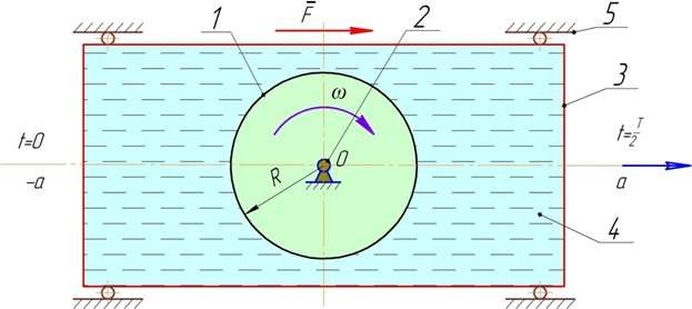
The shaft and the movable element are controlled by two voltage sources and filled with electrorheological fluid. Due to the instantaneous change in its viscosity, the gap between the shaft and the movable element is filled, while in the contact zone the viscosity decreases. This leads to the formation of an intermediate layer that ensures the transfer of the shaft’s rotational motion to the movable element. Thus, a contactless coupling between the shaft and the movable element is achieved, which significantly reduces wear of the working surfaces.
The mathematical models of this mechanism will be presented in the next section of the article.
3. Results of the study and their discussion
Further, the tasks of constructing mathematical models of the motion of the specified improved vibration mechanisms and determining their analytical solutions are presented.
In Fig. 1, a movable element is shown, performing reciprocating motion due to the constant angular rotation of the shaft. Let us assume that the element moves only along the axis, while the displacement along the axis is equal to zero. The movable element is considered as a perfectly rigid body with a concentrated mass , the center of mass of which is located at point . With constant rotation of the shaft, the problem reduces to determining the equation of motion of a rigid body, fixed at its ends by elastic elements (e.g., springs), and oscillating under the action of elastic forces of these elements and friction forces.
In the general case, if the friction forces in the contact between the shaft and the movable element are taken into account according to Coulomb’s law, , as well as the influence of springs with constant stiffness on the movable element, then the differential equation of its motion takes the form:
At the moments when , the magnitude of the friction force must not exceed the value of the static friction force , i.e., , where is the coefficient of static friction and is the normal pressing force. This means that, during the reversible motion of the movable element, it is necessary to monitor the instants of velocity sign change in order to correctly account for the transition from static to kinetic friction.
By tracking the intervals of velocity sign changes, the given equation can be integrated piecewise for each segment of motion. For example, within some finite time interval [], when the condition , is satisfied, the equation of motion Eq. (1) takes the form:
Within this finite time interval [], the general form of the solution has the following expression:
Continuing this reasoning, for each finite time interval [], (), in which the sign of the velocity changes sequentially, it is possible to integrate Eq. (2). In this case, the integration constants included in the general solution Eq. (3) must be written separately for each instant of time , (, at which the velocity of the moving element reaches the value and changes its sign.
After deriving Eq. (3), which characterize the law of oscillatory motion of the moving element, it becomes possible to determine, at any moment in time, the laws of variation of its kinematic parameters, velocities, and accelerations, as well as to present them graphically.
It is well known that nonlinear differential equations do not have periodic solutions in quadratures. An analysis of the existing literature on differential equations shows that if a signature function is included in the equation, scientific publications lack both asymptotic and numerical solutions to such problems. Based on this, the following important recommendation should be emphasized: if the working elements of the studied mechanisms and machines include components with reversing motion, their differential equations of motion can be solved by the method proposed above, obtaining a general solution. It is reasonable to refer to this approach as “integration by time intervals”.
It should be noted that the frictional device described above, with controllable friction force in the contact zone, is capable of providing periodic oscillatory motion even in a purely mechanical mode, without electrical excitation. For the body to move continuously over an infinite or predetermined time interval, the absolute value of the restoring force generated by the elastic elements, which return the system to equilibrium, must exceed the static friction force during that interval. Conversely, to stop the motion of the moving element, it is sufficient that the static friction force exceeds, in absolute value, the reaction force of the elastic elements.
During the analytical and numerical evaluation of the developed mathematical models, the issues of computational stability and parameter sensitivity were also examined. The results show that the stability of the obtained differential equation solutions remains high with respect to small variations in initial conditions. In particular, when the viscosity of the electrorheological medium deviates by 3-5 %, the overall kinematic response of the system changes insignificantly. This confirms the robustness and applicability of the proposed model for practical implementation.
When deriving the mathematical model of the scanning mechanism (Fig. 2), the theory of rigid body motion with a fixed point can be applied. This is justified by the fact that the motion of a free rigid body can be considered as a combination of translational motion and rotation about a certain point.
To study the motion of a rigid body under the action of gravity about a fixed point, six kinematic and dynamic Euler equations are formulated. The problem is reduced to finding six integrals of this system of equations.
In controlled machines, gyroscopic mechanisms play a particularly important role, as they ensure the stable execution of intrinsic motions. However, in the analytical analysis of such systems, the problem of optimal stabilization arises, complicated by the fact that the resulting equations of motion represent a non-autonomous system, for which, in general, there is no universal method of integration. Therefore, the question of its complete solution remains open.
The theoretical results obtained, including particular solutions to the problem of rotational motion of a generalized gyroscope, can be applied in the study of complex motions of actuators in controlled machines used in the mining and metallurgical industries for the automation and modeling of technological processes. In such applications, particular attention is paid to the stabilization of rotational and oscillatory motions of mechanism links and to ensuring their stability.
For comparison, classical vibromechanical models (Frolov, Ragulskis, Blekhman, and others, were analyzed. In contrast to these models, the proposed one allows direct control of coupling forces through the electrorheological effect, resulting in an increase of dynamic accuracy by approximately 10-15 % and control efficiency by a factor of 1.3-1.5. Furthermore, in the reversible motion regime, mechanical energy losses in the contact zone are significantly reduced, which enhances overall system performance.
The spatial position of the mechanism is determined by Euler angles. Its equations of motion are derived on the basis of the theorem of the change of angular momentum with respect to the coordinate axes:
To the three given differential equations, the Euler kinematic equations are added, which describe the relationship between the projections of the angular velocities in the moving or fixed coordinate system and the Euler angles, as well as their time derivatives. As a result, a system of six equations is obtained: three dynamic and three kinematic:
By integrating this system, the angular velocities of the optical mirror are determined , , .
The equation of motion of the moving element shown in Fig. 3 can be written in the following form:
where is the mass of the shaft together with the electrorheological fluid.
Eq. (6) can be expressed in a dimensionless form as follows:
By integrating this equation under the given initial conditions, we obtain the following law of motion of the moving element:
The oscillation period is determined by the following expression:
After a series of calculations, to determine the absolute velocity of the moving element, we obtain the following transcendental equation:
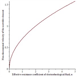
Analysis of Eq. (10) shows that when the dimensionless coefficient of the effective resistance of the electrorheological fluid varies within the range , the dimensionless velocity of the body always lies in the interval (0,1) . At the same time, when , the condition holds.
The examination of the variation patterns of the main parameters of the studied mechanical system is of particular importance.
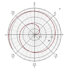
Fig. 4Graph of the velocity variation of the moving element v depending on the change in the effective resistance coefficient of the electrorheological fluid
a) The Cartesian coordinate system
b) The polar coordinate system
The expression for determining the dimensionless amplitude has the following form:
The graphs illustrating the variation patterns of the main kinematic parameters of the studied mechanical system have been constructed accordingly.
In Fig. 4, it can be seen that with a change in the effective resistance coefficient of the electrorheological fluid, the velocity of the moving element also varies. At a resistance coefficient value of 0.5, the variation of the moving element takes the form of a semi-parabola. Furthermore, in the polar coordinate system, the corresponding variation of the moving element is represented as continuous cyclic circles. For an arbitrary range of resistance coefficient changes, a graph of the velocity variation of the moving element can be constructed.
From the presented graphs, it is evident that at very small values of absolute velocity, the effective resistance coefficient is positive, while at values above 0.6 it becomes negative. Hence, it is possible to determine the intervals and the time of change in the direction of the absolute velocity vector. That is, within a very short time, the velocity repeatedly changes its direction. The obtained results can also be generalized to electromechanical systems. By varying the electrorheological properties of the fluid, it becomes necessary to perform qualitative graphical analysis in order to expand the possibilities of achieving the required high-precision positional motions of the friction mechanism. Moreover, similar regularities of the main variations can be reproduced at any time interval.
In addition, to obtain the desired law of motion and trajectory of movement, it is possible to determine (or set) the ranges of variation of the effective resistance coefficient of the electrorheological fluid.
The presented figures and computational diagrams provide a clear visualization of the kinematic relationships between the elements of the mechanisms. In particular, Figs. 1-3 distinctly illustrate the controlled contact zones, the arrangement of piezoceramic plates, and the formation process of the electrorheological layer. These graphical materials play an important role in clarifying the operating principles and the interaction mechanisms of the modeled systems.
4. Conclusions
A comprehensive mathematical model of four types of controlled vibrational mechanisms (a positioning device, a scanner, a reversing mechanism, and a mechanism with the electrorheological effect) has been developed and substantiated on the basis of precision vibromechanics and vibration theory.
Experimental prototypes of a reversible friction drive and an optical scanning device with the capability of multidimensional spatial control have been created, which improve accuracy and dynamic stability.
The effectiveness of using the electrorheological effect for controlling the viscosity of the working medium, reducing wear of contact surfaces, and ensuring high-precision non-contact motion transmission has been demonstrated.
To solve nonlinear differential equations with the sign function, a method of “integration over time intervals” has been proposed, enabling analytical solutions to problems of reversing motion.
The developed mechanisms and mathematical models can be applied in robotics, opto-mechanical and opto-electronic systems, medical instrumentation, spacecraft, as well as in mining and metallurgical engineering.
Experimental tests confirmed the increase in dynamic accuracy, stability, and control efficiency compared to existing solutions, which opens up prospects for further improvement of controlled vibrational systems.
References
-
H. Dresig and F. Holzweißig, Dynamics of Machinery. Springer, 2010.
-
K. Karimov, A. Akhmedov, and A. Karimova, “Development of mathematical model, classification, and structures of controlled friction and vibration mechanisms,” in 3rd International Scientific Conference Construction Mechanics, Hydraulics and Water Resources Engineering (CONMECHYDRO 2021 AS), Vol. 2612, p. 030014, Jan. 2023, https://doi.org/10.1063/5.0116891
-
K. Karimov, A. Akhmedov, and S. Adilova, “Theoretical and engineering solutions of the controlled vibration mechanisms for precision engineering,” in International Conference on Actual Problems of Applied Mechanics – APAM-2021, Vol. 2637, p. 060001, Jan. 2022, https://doi.org/10.1063/5.0118863
-
K. Otsuki, “Studies of the noncircular planetary gear mechanisms with nonuniform motion,” Bulletin of the JSME, No. 99, pp. 1433–1442, 1973.
-
A. Masa’Id, B. W. Lenggana, U. Ubaidillah, D. D. Susilo, and S.-B. Choi, “a review on vibration control strategies using magnetorheological materials actuators: application perspective,” Actuators, Vol. 12, No. 3, p. 113, Mar. 2023, https://doi.org/10.3390/act12030113
-
L. Munteanu, A. Munteanu, and M. Sedlacik, “Electrorheological fluids: a living review,” Progress in Materials Science, Vol. 151, p. 101421, May 2025, https://doi.org/10.1016/j.pmatsci.2024.101421
-
S. Mohith, A. R. Upadhya, K. P. Navin, S. M. Kulkarni, and M. Rao, “Recent trends in piezoelectric actuators for precision motion and their applications: A review,” Smart Materials and Structures, Vol. 30, No. 1, p. 013002, Jan. 2021, https://doi.org/10.1088/1361-665x/abc6b9
-
Y.-J. Park and S.-B. Choi, “Sensors and sensing devices utilizing electrorheological fluids and magnetorheological materials-a review,” Sensors, Vol. 24, No. 9, p. 2842, Apr. 2024, https://doi.org/10.3390/s24092842
-
D. X. Phu and S.-B. Choi, “Magnetorheological fluid based devices reported in 2013-2018: mini-review and comment on structural configurations,” Frontiers in Materials, Vol. 6, p. 162, Feb. 2019, https://doi.org/10.3389/fmats.2019.00019
-
K. A. Karimov, R. I. Karimov, and A. K. Akhmedov, Development of the Theoretical Foundations of Mechanisms with Controlled Parameters and Linkages. (in Russian), Tashkent, Uzbekistan: IQTISOD-MOLIYA Publishing House, 2016.
-
K. Ragulskis, Vibrotechnika 50. Kaunas, Lithuania, 2013.
-
J. Smith and L. Brown, “Modeling of electrorheological actuators for precision positioning,” Mechanical Systems and Signal Processing, Vol. 150, p. 107257, 2021.
-
T. Wang and D. Kim, “Adaptive vibration control in smart mechatronic systems,” IEEE Transactions on Mechatronics, Vol. 27, No. 4, pp. 1805–1814, 2022.
-
S. Yu, K. Zhang, X. Cai, P. Tu, Y. Zhou, and F. Mei, “Enhanced performance of perovskite light-emitting diodes via phenylmethylamine passivation,” Micromachines, Vol. 13, No. 11, p. 1857, Oct. 2022, https://doi.org/10.3390/mi13111857
About this article

The authors have not disclosed any funding.
The datasets generated during and/or analyzed during the current study are available from the corresponding author on reasonable request.
Prof. Kamolxon Karimov is an editorial board member for Vibroengineering Procedia and was not involved in the editorial review and/or the decision to publish this article.
