Abstract
This paper proposes a hydraulic suspension integrated with an energy-regeneration mechanism for a quarter-car model. A nonlinear dynamic model is built and co-simulated in MATLAB–AMESim under ISO road excitations (Classes A-C) and varying speeds. The system converts vibrational energy to electricity through a hydraulic-mechanical-electrical chain including a rectifying circuit, hydraulic motor, and DC generator. Compared with a conventional suspension, the proposed system improves ride comfort and harvests energy simultaneously. At 20 m/s on ISO-C, the RMS vertical acceleration of the sprung mass decreases by 43.5 %; the maximum regeneration efficiency reaches 14.83 % at 30 m/s. Recovered energy increases with both road roughness and speed, up to 96.04 J at 30 m/s. Results confirm the feasibility of hydraulic regenerative suspensions for enhancing comfort and energy utilization in modern vehicles.
Highlights
- A nonlinear quarter-car model of a hydraulic regenerative suspension is developed and co-simulated in MATLAB-AMESim.
- The system reduces the RMS vertical acceleration of the sprung mass by up to 43.5% under ISO Class C road conditions.
- The maximum energy regeneration efficiency reaches 14.83% at 30 m/s, harvesting up to 96.04 J of vibrational energy.
1. Introduction
The suspension system is essential for vehicle stability and ride comfort, yet a substantial portion of vibration energy is dissipated as heat through conventional dampers. Recovering this wasted energy and converting it into electricity has become a promising approach to enhance overall vehicle efficiency. Previous studies have reported that the energy recovery potential of suspension systems can reach several tens to thousands of watts, especially under rough-road or heavy-load conditions [1-5]. Various energy-regenerative concepts - electromagnetic, mechanical, and hydraulic have been developed, demonstrating the feasibility of simultaneously improving vibration isolation and energy harvesting [6-12]. Recent research on hydraulically interconnected and regenerative suspensions has shown further gains in power recovery, anti-roll stability, and ride comfort [13-15], while control-based and active-seat studies confirm that efficient energy harvesting can be achieved without degrading comfort [16-17]. However, few studies have addressed detailed nonlinear dynamic modeling or the relationship between design parameters and regeneration efficiency, motivating the present investigation.
2. Operating principle
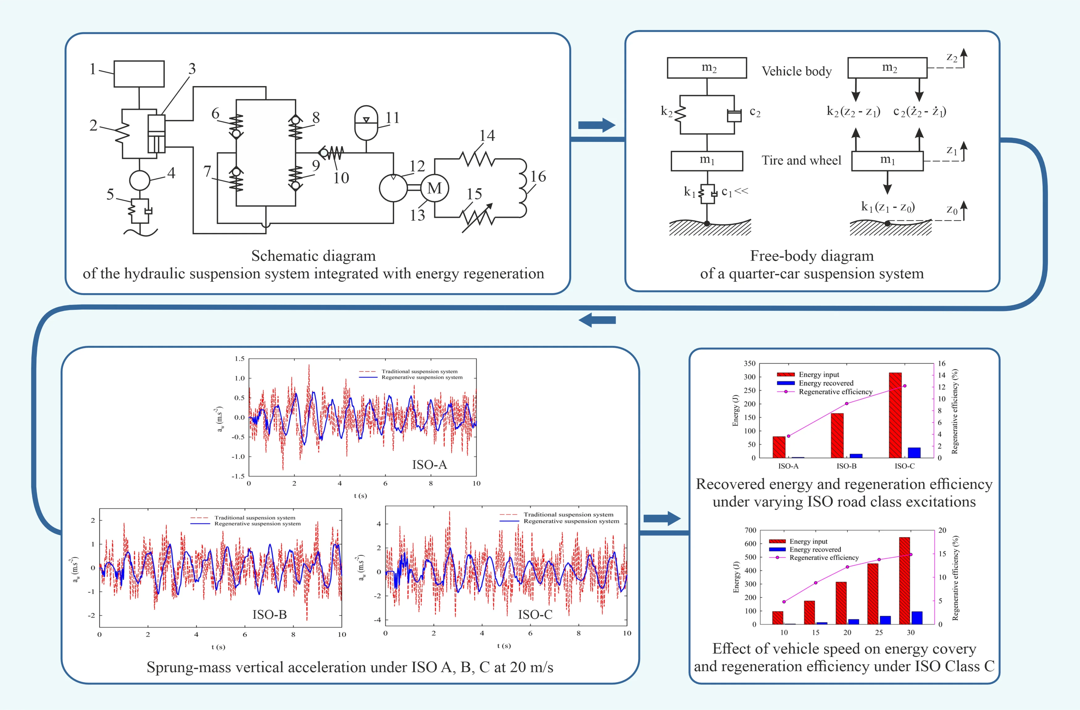
The quarter-car suspension comprises sprung/unsprung masses connected by a spring and a hydraulic damper. Piston motion during compression/rebound drives the working fluid through a four-valve hydraulic rectifier to ensure unidirectional flow toward a hydraulic motor coupled to a DC generator. The generator supplies an external electrical load, harvesting part of the dissipated vibration energy. Fig. 1 shows the schematic with key components (spring, damper, rectifier, accumulator, motor, generator)
Fig. 1Schematic diagram of the hydraulic suspension system integrated with energy regeneration: 1 – sprung mass; 2 – spring; 3 – damper; 4 – unsprung mass; 5 – tire; 6, 7, 8, 9, 10 – check valve; 11 – accumulator; 12 – hydraulic motor; 13 – DC generator; 14 – internal resistance; 15 – external load; 16 – internal inductance
3. Model development and evaluation criteria
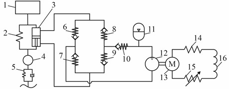
The dynamic behavior of the suspension system is modeled using a quarter-car configuration, as illustrated by the free-body diagram in Fig. 2.
Fig. 2Free-body diagram of a quarter-car suspension system, in which: z0 – road level (displacement); z1 – wheel/tire displacement; z2 – vehicle body displacement; m1 – mass of wheel assembly; m2 – mass of quarter vehicle body; k1 – stiffness of tire; k2 – stiffness of spring; c2 – damping coefficient of shock absorber
3.1. Mathematical model of energy regeneration process
During vehicle motion, vibrations of the wheel and body induce displacement of the piston inside the hydraulic damper. This piston movement generates fluid flow within the hydraulic system, where the flow rates during rebound and compression strokes are defined as follows [18]. Compression and rebound stroke:
where: and – flow rates of the hydraulic fluid through the piping and motor respectively; – annular area (difference between piston head and rod cross-sections); – piston face area; – piston velocity as a function of time. The fluid flow generates torque on the shaft of the hydraulic motor. The relationships among flow rate, pressure difference, rotational speed, and torque are defined by:
where: – angular velocity of the hydraulic motor shaft; – torque at the motor shaft; – the flow rate of hydraulic fluid passing through the hydraulic motor; – motor displacement; – pressure drop across motor ports, and – volumetric and mechanical efficiencies of the hydraulic motor.
The mechanical energy generated is transmitted to a DC generator to produce electrical energy. The relationship between the generator’s back EMF and input torque is expressed as:
where: – angular velocity of the generator; and – back-EMF constant and torque constant; – generator rotor inertia; – generator output current.
Applying Kirchhoff’s voltage law and the total regenerated power is:
where: – internal inductance (in practice, can often be neglected); – internal resistance; – external load resistance.
The hydraulic pressure drop across the motor is given by:
The hydraulic input power and energy regeneration efficiency are defined as:
3.2. Road profile excitation model
In this study, the road excitation profile is constructed based on ISO/TC108 standards using the road roughness coefficient , as shown in Table 1 [19].
Table 1ISO road roughness classification parameters
Road class | Class A | Class B | Class C | Class D |
× 10-6 (m³) | 16 | 64 | 256 | 1024 |
Fig. 3Road surface excitation profile for ISO Class C
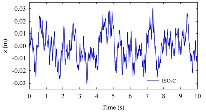
Fig. 3 illustrates the MATLAB-simulated road surface profile corresponding to ISO Class C, which represents high surface roughness typically encountered in real-world driving conditions.
3.3. Comfort of the car ride
Vehicle ride comfort is evaluated following ISO 2631-1:1997 [20], which specifies criteria for human exposure to whole-body vibration. In this study, comfort is quantified by the weighted root-mean-square (RMS) acceleration, serving as a standardized index of vertical vibration severity. By comparing the calculated with the ISO threshold ranges (Table 2), the corresponding comfort levels and potential physiological effects on passengers can be assessed, providing a consistent basis for evaluating suspension performance.
Table 2Comfort Levels by RMS Acceleration
(m/s2) | Level of comfort | (m/s2) | Level of comfort |
< 0.315 | Not uncomfortable | 0.8-1.6 | Uncomfortable |
0.135-0.63 | Somewhat uncomfortable | 1.25-2.5 | So uncomfortable |
0.5-1 | Fully uncomfortable | > 2 | Highly uncomfortable |
4. Simulation and analysis results
To assess the performance of the hydraulic suspension with energy regeneration, dynamic simulations were performed in MATLAB-AMESim and compared with a conventional suspension. The nonlinear quarter-car model equations were solved through co-simulation, and the vehicle parameters, fluid properties, and simulation conditions are summarized in Table 3.
Table 3Parameters of the quarter-car model and simulation conditions
Parameter | Description | Values | Unit | Parameter | Description | Values | Unit |
/ | Unsprung/ sprung mass | 45/400 | kg | Motor displacement | 10 | cc/rev | |
Damping coefficient | 1500 | N.s/m | Cracking pressure of CV | 0,2 | bar | ||
Spring stiffness | 23000 | N/m | Initial gas pressure | 20 | bar | ||
Tire stiffness | 265350 | N/m | Test temperature | 40 | °C | ||
Piston diameter | 40 | mm | Density of fluid | 802 | kg/m3 | ||
Rod diameter | 20 | mm | Bulk modulus | 17000 | bar | ||
Length of stroke | 0.3 | m | Absolute viscosity | 51 | cP |
To assess ride comfort performance for both suspension configurations, simulation scenarios were developed using road excitation inputs based on three ISO standard roughness levels: ISO-A, ISO-B, and ISO-C. The vehicle speed was maintained at a constant 20 m/s to ensure comparability across the cases. The vertical acceleration of the sprung mass was adopted as the primary performance indicator and is presented in Fig. 4.
Fig. 4Sprung-mass vertical acceleration under ISO A, B, C at 20 m/s
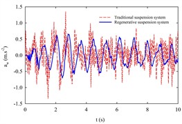
a) ISO-A
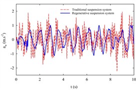
b) ISO-B
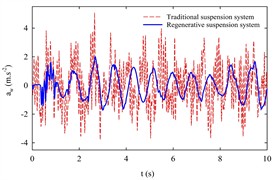
c) ISO-C
Fig. 4 illustrate the vertical acceleration responses of the sprung mass under ISO-A, ISO-B, and ISO-C road excitations at 20 m/s. The regenerative suspension yields RMS accelerations of 0.303, 0.533, and 0.847 m/s2, corresponding to vibration reductions of 17.5 %, 19.2 %, and 43.5 %, respectively, compared with the conventional system (Table 4). According to ISO 2631, the regenerative suspension improves ride comfort from the “somewhat uncomfortable” to “not uncomfortable” range for ISO-A, and significantly mitigates discomfort under rougher road conditions (ISO-B and ISO-C).
Table 4Percentage reduction in RMS acceleration by road surface condition
Road roughness levels | ISO-A | ISO-B | ISO-C |
regenerative suspension system (m/s2) | 0.303 | 0.533 | 0.847 |
conventional suspension system (m/s2) | 0.367 | 0.660 | 1.498 |
Reduction (%) | 17.5 | 19.2 | 43.5 |
Across all road classes (ISO-A, ISO-B, and ISO-C) at a constant speed of 20 m/s, the regenerative hydraulic suspension shows consistently superior performance, reducing body vibration and partially recovering dissipated energy, thereby improving both ride comfort and overall efficiency. To further examine its energy-regeneration capability, simulations were performed at 20 m/s over ISO-A-C road profiles (Fig. 5) and under ISO-C excitation at different vehicle speeds (10-30 m/s, Fig. 6).
Fig. 5Recovered energy and regeneration efficiency under varying ISO road class excitations
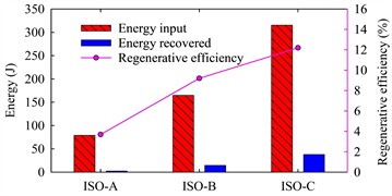
Fig. 6Effect of vehicle speed on energy covery and regeneration efficiency under ISO Class C
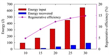
Fig. 5 illustrates the influence of road roughness on energy regeneration. As the surface condition deteriorates from ISO-A to ISO-C, the vibrational input energy increases from 79.4 J to 315.7 J, while the harvested energy rises from 2.93 J to 38.51 J. Correspondingly, the regeneration efficiency improves from 3.69 % to 12.2 %, indicating that rougher roads provide greater vibration amplitude and thus higher energy-harvesting potential. Fig. 6 shows the effect of vehicle speed on regeneration performance under ISO-C excitation. As speed increases from 10 m/s to 30 m/s, the recovered energy grows from 4.67 J to 96.04 J, and the efficiency from 4.79 % to 14.83 %. This trend confirms that higher speeds intensify suspension vibration, enhancing the conversion of mechanical energy into electrical power.
5. Conclusions
This study presented a nonlinear quarter-car model of a hydraulic suspension system integrated with energy regeneration, evaluated through MATLAB-AMESim co-simulation. Compared with a conventional system, the proposed design significantly improves both ride comfort and energy recovery. Under ISO-C excitation, the RMS vertical acceleration decreases from 1.498 m/s2 to 0.847 m/s2 (a 43.5 % reduction), with corresponding reductions of 17.5 % and 19.2 % for ISO-A and ISO-B. The recovered energy increases from 2.93 J to 38.51 J, reaching a maximum regeneration efficiency of 14.83 % at 30 m/s. These results verify the feasibility and practical potential of hydraulic regenerative suspensions for improving energy efficiency and ride comfort in modern, especially electric and hybrid, vehicles.
References
-
I. Martins, J. Esteves, G. D. Marques, and F. P. Dasilva, “Permanent-magnets linear actuators applicability in automobile active suspensions,” IEEE Transactions on Vehicular Technology, Vol. 55, No. 1, pp. 86–94, Jan. 2006, https://doi.org/10.1109/tvt.2005.861167
-
Y. Zhang, K. Huang, F. Yu, Y. Gu, and D. Li, “Experimental verification of energy-regenerative feasibility for an automotive electrical suspension system,” in 2007 IEEE International Conference on Vehicular Electronics and Safety (ICVES 2007), Dec. 2007, https://doi.org/10.1109/icves.2007.4456407
-
R. B. Goldner, P. Zerigian, and J. R. Hull, “A preliminary study of energy recovery in vehicles by using regenerative magnetic shock absorbers,” in SAE International Government/Industry Meeting, Vol. 1, May 2001, https://doi.org/10.4271/2001-01-2071
-
Y. Zhang, K. Guo, D. Wang, C. Chen, and X. Li, “Energy conversion mechanism and regenerative potential of vehicle suspensions,” Energy, Vol. 119, pp. 961–970, Jan. 2017, https://doi.org/10.1016/j.energy.2016.11.045
-
C. Wei and H. Taghavifar, “A novel approach to energy harvesting from vehicle suspension system: Half-vehicle model,” Energy, Vol. 134, pp. 279–288, Sep. 2017, https://doi.org/10.1016/j.energy.2017.06.034
-
R. Zhang and X. Wang, “Parameter study and optimization of a half-vehicle suspension system model integrated with an arm-teeth regenerative shock absorber using Taguchi method,” Mechanical Systems and Signal Processing, Vol. 126, pp. 65–81, Jul. 2019, https://doi.org/10.1016/j.ymssp.2019.02.020
-
S. Li, J. Xu, X. Pu, T. Tao, H. Gao, and X. Mei, “Energy-harvesting variable/constant damping suspension system with motor based electromagnetic damper,” Energy, Vol. 189, p. 116199, Dec. 2019, https://doi.org/10.1016/j.energy.2019.116199
-
Z. Wu, Y. Xiang, M. Li, M. Y. Iqbal, and G. Xu, “Investigation of accumulator main parameters of hydraulic excitation system,” Journal of Coastal Research, Vol. 93, No. sp1, p. 613, Sep. 2019, https://doi.org/10.2112/si93-083.1
-
M. A. A. Abdelkareem et al., “Analysis of the prospective vibrational energy harvesting of heavy-duty truck suspensions: A simulation approach,” Energy, Vol. 173, pp. 332–351, Apr. 2019, https://doi.org/10.1016/j.energy.2019.02.060
-
Y. Okada and H. Harada, “Active and regenerative control of electrodynamic vibration damper,” in ASME 1995 Design Engineering Technical Conferences collocated with the ASME 1995 15th International Computers in Engineering Conference and the ASME 1995 9th Annual Engineering Database Symposium, pp. 595–602, Sep. 1995, https://doi.org/10.1115/detc1995-0621
-
Z. Li, L. Zuo, G. Luhrs, L. Lin, and Y.-X. Qin, “Electromagnetic energy-harvesting shock absorbers: design, modeling, and road tests,” IEEE Transactions on Vehicular Technology, Vol. 62, No. 3, pp. 1065–1074, Mar. 2013, https://doi.org/10.1109/tvt.2012.2229308
-
Z. Li, L. Zuo, G. Luhrs, L. Lin, and Y.-X. Qin, “Design, modeling, and road tests of electromagnetic energy-harvesting shock absorbers,” in ASME 2012 5th Annual Dynamic Systems and Control Conference joint with the JSME 2012 11th Motion and Vibration Conference, pp. 675–684, Oct. 2012, https://doi.org/10.1115/dscc2012-movic2012-8734
-
J. Zou, X. Guo, M. A. A. Abdelkareem, L. Xu, and J. Zhang, “Modelling and ride analysis of a hydraulic interconnected suspension based on the hydraulic energy regenerative shock absorbers,” Mechanical Systems and Signal Processing, Vol. 127, pp. 345–369, Jul. 2019, https://doi.org/10.1016/j.ymssp.2019.02.047
-
J. Lu et al., “Optimal design of an integrated electromagnetic linear energy regenerative suspension system based on a hybrid optimization objective,” Energy, Vol. 327, p. 136176, Jul. 2025, https://doi.org/10.1016/j.energy.2025.136176
-
P. Liu, F. Kou, Y. Chen, G. Wang, and L. Xing, “Modeling and dynamic analysis of a novel energy-regenerative hydraulically interconnected suspension,” Energy, Vol. 324, p. 135928, Jun. 2025, https://doi.org/10.1016/j.energy.2025.135928
-
I. Maciejewski, S. Pecolt, T. Krzyzynski, and T. Krolikowski, “Modelling and simulation of the energy regenerative system for active horizontal seat suspension driven by an induction motor,” Procedia Computer Science, Vol. 225, pp. 3372–3380, Jan. 2023, https://doi.org/10.1016/j.procs.2023.10.331
-
R. Azmi, M. Mirzaei, and A. Habibzadeh-Sharif, “A novel optimal control strategy for regenerative active suspension system to enhance energy harvesting,” Energy Conversion and Management, Vol. 291, p. 117277, Sep. 2023, https://doi.org/10.1016/j.enconman.2023.117277
-
Z. Wu and G. Xu, “Modeling and analysis of a hydraulic energy-harvesting shock absorber,” Mathematical Problems in Engineering, Vol. 2020, pp. 1–11, Feb. 2020, https://doi.org/10.1155/2020/1580297
-
M. M. Moheyeldein, A. M. Abd-El-Tawwab, K. A. Abd El-Gwwad, and M. M. M. Salem, “An analytical study of the performance indices of air spring suspensions over the passive suspension,” Beni-Suef University Journal of Basic and Applied Sciences, Vol. 7, No. 4, pp. 525–534, Dec. 2018, https://doi.org/10.1016/j.bjbas.2018.06.004
-
“Mechanical vibration and shock-Evaluation of human exposure to whole-body vibration, Part I: General requirements,” ISO 2631-1, 1997.
About this article

The authors have not disclosed any funding.
The datasets generated during and/or analyzed during the current study are available from the corresponding author on reasonable request.
The authors declare that they have no conflict of interest.
