Abstract
For achieving the control of hydraulic-electricity energy regenerative suspension (HERS), a novel control algorithm, net power control (NPC), is applied in this study. A HERS unit as a new energy reclaiming suspension device is equipped with an energy-harvesting hydraulic-electricity shock absorber (HESA). The composition and classification of HESA damping force were analyzed based on the basic working principle of HESA. Thus, the mathematical model of HESA damping force is deduced as a function of suspension dynamic speed and load current. A series of experiments were made to verify the reliability of the model. Based on the energy flow analysis of the suspension system, the net power flowing into the suspension is calculated. In order to minimize the vibration acceleration of the vehicle body, a novel net power control is proposed. The comparison result indicates the control effect of NPC is more significant than skyhook control, especially in the high excitation frequency. Also, the HERS bench test was carried out to verify the feasibility of NPC. The related results show that the maximum acceleration of the vibration is improved by 34.23 % with NPC on bump pavement excitation. And on B-class random road, the root mean square (RMS) value of the sprung mass vibration acceleration is reduced by 65 %. Furthermore, the influence of suspension dynamic velocity and deflection on the optimal control load current is obtained.
1. Introduction
Recently, with energy saving and fuel efficiency getting more and more concern, regenerative suspension systems are taken into consideration. Regenerative suspension is a new type of suspension system that can recycle the vibration energy. The traditional damper suppresses the disturbance from the road excitation by dissipating the energy into heat. While in the regenerative suspension system, the energy regenerative shock absorber was applied to convert mechanical energy into electrical energy and charge the battery directly. The system not only can reduce fuel consumption and pollutant emissions, but also improve vehicle performance. It indicates a new development direction for electronic suspension system.
Different strategies of regenerative suspension systems have been investigated by many researchers. Suda et al. developed a self-powered active suspension with two linear DC motors (one as an energy regenerative damper recycling the kinetic energy; and the other one as an actuator) and the corresponding tests proved that their hybrid suspension unit may improve the isolation performance especially at high frequency [1], moreover, one linear DC motor may also be used to realize the active control and energy recovery [2, 3]. Kawamoto et al. proposed an active suspension structure integrating a ball screw mechanism and an electro-mechanical actuator [4]. The measured results indicate the regenerated power is 33 W [5]. Kowal et al. [6] put forward an electro-hydraulic self-powered suspension system which can accumulated energy in a pneumohydraulic accumulator. Ebrahimi et al. [7, 8] proposed a self-powered hybrid linear EM damper to improve ride comfort. David and Bobrovsky also applied a linear motor to active suspension to achieve energy regeneration [9]. Li et al. presented a regenerative shock absorber including a rack and pinion mechanism, in which a gearbox is equipped to increase rotational speed [10]. Sabzehgar et al. [11] designed a novel energy-regenerative suspension mechanism coupled with an algebraic screw kinematic pair and a rotary permanent magnet synchronous generator. The related experiment results indicated the scheme can provide a high energy recovery efficiency.
Different from conventional passive suspension, the regenerative suspension systems should have the functions of capturing energy within a wide range of excitation frequencies and suppressing the road disturbance to improve the passengers’ comfort. Thus, the study of the regenerative suspension control strategy is full of importance.
Suda et al. [12] proposed a hybrid control system with active control and energy regeneration to achieve good performance of vibration reduction with few energy consumption. The numerical simulations and basic experiments proved that the proposed hybrid control system had satisfactory performance in both vibration reduction and energy consumption. For making the regeneration vibration energy meet the requirements of control, Suda et al. [1] studied less energy consumed active control law using the concept of skyhook control. From experiments and numerical simulations, it is confirmed that the self-powered active suspension system has better isolation performance than passive or semi-active suspension system without any energy consumption. Gysen et al. [13] proposed a regenerative direct-drive electromagnetic active suspension, which both deliver active forces and regenerate power. In the study, a linear quadratic regulator (LQR) controller is developed for the improvement of comfort and handling. The tests results indicate that the electromagnetic suspension system can significantly improve both comfort and handling with minimal power requirements of between 150~300 W overall power consumption for the total vehicle, depending on road conditions and objectives. Di Iorio et al. [14] proposed a novel multiobjective control design method for regenerative vehicle suspension systems. Besides the usual control objectives for performance, it includes the amount of energy to be harvested as a further conflicting objective and allows the designer to directly trade-off among them. Also, the simulation results showed that the performance/harvesting trade-off can be dealt with effectively by active control laws-MIPC. In the study of Roshan et al. [15], a sliding mode controller along with a three-phase boost converter were utilized to develop a semi-active regenerative suspension system. Through controlling the current and damping force of linear machine, the required mechanical damping determined by the system condition was provided.
Hydraulic-electricity energy regenerative suspension (HERS) system with HESA is proposed in this paper. Aiming to achieve the control of the semi-active regenerative suspension system, the composition and classification of HESA damping force were analyzed in this paper. According to the characteristics of the damping force, a novel control law is put forward to minimize the vibration acceleration of the vehicle body. Also, the experimental verification was carried out to prove the feasibility of the controller.
2. Dynamic model of a regenerative suspension system
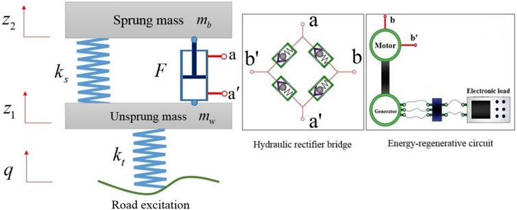
According to [16], the so-called ‘quarter-car model’ (Two-DOF) has been proved to estimate the dynamic behavior of an actual road vehicle in terms of discomfort, road holding and working. A two-DOF suspension system is demonstrated in Fig. 1, and the damping force of semi-active shock absorber is represented by . The equations of motion for this system are obtained by Newton’s second law as:
where: and represent the sprung and unsprung masses, respectively; and represent the vertical displacements of sprung and unsprung masses, respectively; represents the road input displacement; and represent the suspension stiffness and tire stiffness, respectively.
Define the vector , , where, , , , , , , so the system state equation can be expressed as:
where:
Fig. 1Two-DOF semi-active suspension system
3. Damping force of HESA
In energy regenerative suspension, HESA acts as an energy recovery and provides the required damping force to attenuate the vibration. According to the basic working principle of HESA [17], it is clear that the damping force of the HESA is mainly caused by the pressure drop of the hydraulic system in the extension and compression stroke, as shown in Fig. 2.
Fig. 2Stress of the shock absorber piston
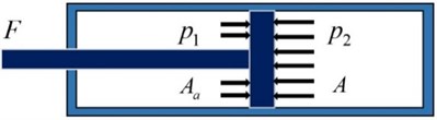
In Fig. 2: represents the pressure of the upper operating chamber; represents the pressure of the lower operating chamber; represents the piston ring area on the side of the upper operating chamber; and represents the piston cross-sectional area. In compression stroke, the damping force can be expressed as:
The working principle of HESA is shown in Fig. 3.
Fig. 3Schematics of HESA
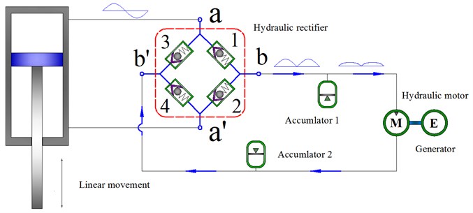
The damping force is primarily from the pressure drop of hydraulic pipelines, check valves and the motor-generator system in HESA while the internal leakage of the oil cylinder and the local pressure loss are neglected, the following pressure balance equation is existed in compression stroke:
where: represents the pressure drop of the check valve; represents the pressure drop of a hydraulic motor; and represents the pressure drop of a hydraulic pipe.
While ignoring the pressure drop between accumulator 2 and lower working chamber, the following equation comes into existence for and :
From Eqs. (3-5), the following equation may be obtained:
where: represents the cross-sectional area of a piston rod, .
Similarly, the following equations also come into existence in extension stroke:
where represents the damping force in extension stroke. So, the damping force can be expressed as:
In summary, the mathematical expression of the damping force of HESA can be written as:
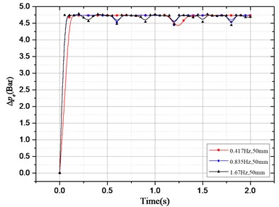
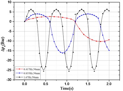
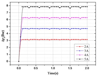
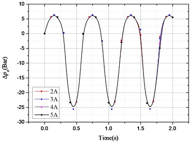
According to above damping force expression, the pressure drop that provides the HESA damping force can be divided into two parts: one is the oil pressure drop caused by the hydraulic motor system; the other is the oil pressure drop caused by the check valve, hydraulic pipelines, accumulators, etc. In order to study the effect of different excitation and different electronic load on pressure drop, the following two groups of simulation experiments were carried out. The results are shown in Fig. 4:
a) The electronic load current is 3 A, the amplitude of sinusoidal excitation is 50 mm, the excitation frequency is 0.417 Hz, 0.825 Hz and 1.67 Hz respectively;
b) Sinusoidal excitation amplitude and frequency of 50 mm and 1.67 Hz, the electronic load current of 2 A, 3 A, 4 A and 5 A.
Fig. 4Pressure drop changes with excitation and electronic load current: a) ∆pe changes with different excitation frequency; b) ∆pa changes with different excitation frequency;
a)
b)
c)
d)
c)changes with different load current; d)changes with different load current
In Fig. 4(a), when the response reaches stabilization, only occurs locally in small oscillations under the condition of different excitation and same electronic load. The overall basically remain unchanged; in Fig. 4(b), with the same electronic load, varies obviously with different excitation. Thus, we can conclude that the excitation has an effect on, but no effect on.
In Fig. 4(c), when the response reaches stabilization, changed with different load current under the condition of same excitation; in Fig. 4(d), is almost unchanged with electronic load. So, the electronic load current only has an impact on, but not on.
According to the conclusions above, the damping force of HESA also can be divided into two parts: one part is provided by hydraulic rectifier, hydraulic pipelines, accumulators, etc., and this part has nothing to do with the electronic load, only with the road excitation, so it is uncontrollable. Therefore, it can be expressed as a function of suspension dynamic speed , namely:
The other part is provided by hydraulic motor system, which varies with different load current and has nothing to do with road excitation. And it is controllable. So, it can be expressed as a function of electronic load current , that is:
Eq. (11) shows that the damping force caused by hydraulic motor system can be expressed as:
As an energy conversion unit, a hydraulic motor converts the oil pressure in the hydraulic system to the mechanical energy. The expansion pressure energy may be turned into the torque to the generator. The hydraulic motor rotary speed and output torque may be calculated by the following equations:
where: represents the hydraulic motor rotary speed; represents the flux of hydraulic motor; represents the displacement of the hydraulic motor; represents the volume efficiency of the hydraulic motor; represents the output torque of the hydraulic motor; and represents the mechanical efficiency of the hydraulic motor.
The generator is driven by a hydraulic motor so that its voltage and torque shall meet the following equations:
where: represents the induction electromotive force; represents the back electromotive force constant; represents the rotate speed of the generating rotor (; represents the output torque of the hydraulic motor; represents the rotary inertia of the generating rotor; represents the torque constant of the generator; and represents the inductive current.
While ignoring the rotary inertia of the generating rotor, the following equation can be obtained from Eq. (15) and (16):
Thus, the function expression of is deduced as follows:
The Eq. (18) shows that when the electronic load current is zero, the damping force caused by hydraulic motor system is zero. At this time, the damping force of HESA is , which is caused by hydraulic rectifier, hydraulic pipelines and accumulators. Thus, a series of experiments were conducted to explore the relationship between and . The amplitude of the sinusoidal excitation is 50 mm and the frequency is 0.418 Hz, 0.835 Hz and 1.67 Hz respectively. The results are shown in Fig. 5.
Fig. 5Damping characteristic curve of HESA
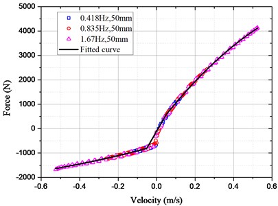
The relationship between and was piecewise fitted according to the data points. The expression for the fitting curve is:
From Eqs. (18) and (19), the expansion damping force of HESA may be calculated by:
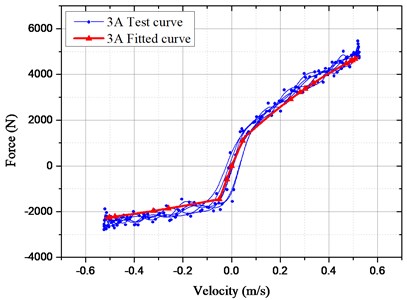
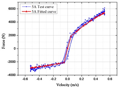
For verifying the accuracy of the mathematical model, the bench test of HESA was conducted, as shown in Fig. 6. The measured and simulated results in Fig. 7 were compared under the sinusoidal frequency and amplitude (1.67 Hz and 50 mm). The electronic load currents are 3 A and 5 A respectively.
Owing to the oil transportation characteristics, there exists oil loss travel distortion in actual tests so that the damping force may be distorted locally. However, performances of the damper may not be influenced distinctly. When the load current is 3 A, it is found based on the verification experiments, the actual maximum damping force is 5453.4 N and the simulated one is 4989.2 N with the difference of only 8.51 %; And the difference is 9.8 % in the case of 5 A. Thus, the simulated and measured damping forces are in good agreement and the deduced mathematical model of HESA is reliable in the vehicle suspension system.
Fig. 6Test rig of HESA
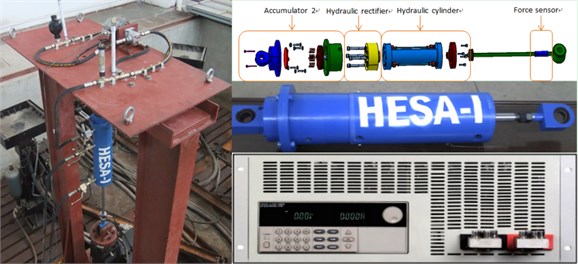
Fig. 7Comparison of test and fitted results
4. Statement of NPC control law
Generally, the so-called driving performance can be evaluated in terms of ride comfort, road holding and suspension safety. Among which, the ride comfort is usually the major concern for the passengers. According to the human sensitivity, a comfortable ride feeling is always mainly related to a small vertical acceleration of human body and chassis. Therefore, the particular goal of semi-active control in this paper is to minimize the vertical chassis acceleration under the real uneven road disturbance excitation.
In order to minimize the vibration acceleration of the vehicle body, it is required that the vibration energy transferred from the suspension system to the vehicle body be as small as possible. So, the transmission energy of the suspension system should be analyzed. According to the Newtonian mechanics, Power is equal to force time velocity, the chassis’ power absorbed by the HESA is:
where denotes the equivalent damping coefficient of HESA.
The chassis’ power absorbed by the suspension spring is:
The power which HESA releases to the tire is:
The power which the suspension spring releases to the tire is:
Thus, the net power flowing into the suspension is:
From Eqs. (21-25), the net power flowing into the suspension can be calculated by:
At same instant, the value of each component’s power flow represent its own energy transferring ability. So, for a quarter car, from another point of view, the ability of vehicle suspension to decouple the energy between the chassis and tire can be evaluated by the value of net power of the suspension. The closer to zero the value of is, the better energy isolation the suspension performs. And the control strategy is defined as net power control (NPC) law.
At the right side of Eq. (26), the second term, , is always non-negative. And represents the damping force of the HESA. If the suspension displacement is represented by , the Eq. (26) can also be simply re-written as:
When , in order to minimize the net power, the value of should be as small as possible. So the electronic load current . Due to the non-negativity of the electronic load current, the damping force of the HESA has a boundary. Thus when , considering the damping force model of HESA, a discussion is given below:
Assuming that , obtained . In compression stroke, is bounded by the maximum boundary condition :
In extension stroke, is also bounded by the minimum boundary condition , thus:
Form Eq. (20), the boundary conditions are clear below:
Synthesize Eqs. (20), (28), (29), (30), (31), got the optimal load current listed as following cases:
Case (1):
Case (2):
Case (3):
Case (4):
Case (5):
5. Stability and effect of the control strategy
5.1. Stability of the control strategy
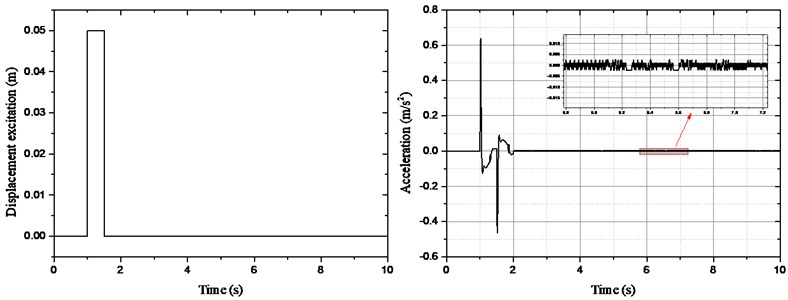
In order to verify the stability of the control system, the simulation analysis of impulse excitation was carried out, as shown in Fig. 8. From the acceleration response curve, the movement of sprung mass tends to zero with the increasing simulation time. So, the closed-loop control system is stable.
Fig. 8Acceleration curve of sprung mass under impulse excitation
Based on the simulation model, the characteristic equation of closed-loop control system is obtained as:
Thus, the characteristic roots were calculated as:
Obviously, the real parts of the characteristic roots are negative. Therefore, we conclude that the closed-loop control system is stable.
5.2. Compared with skyhook control
The skyhook is a very effective control method in semi-active suspension control. The control law is simple without complex state feedback. The control effect is obvious, so it is widely used in semi-active suspension of the engineering products.
According to the study of Sammier [18], the damping force between the sprung mass and the unsprung mass can be expressed as:
The skyhook damping coefficient represents the represents the influence of the vertical velocity of the chassis on the chassis acceleration. represents the controllable damping force and:
From Eqs. (39) and (40), the skyhook damping force can be rewritten as:
The choice of and determines the skyhook suspension [19]. According to control the debugging results, the parameters are chosen as 0.45 and 2100 N·s/m. Thus, the current can be obtained according to Eqs. (20) and (41).
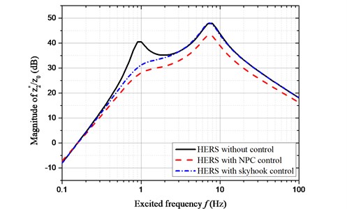
The amplitude-frequency characteristic of is compared between NPC and skyhook control, as shown in Fig. 9. The results indicated that the vibration acceleration has been improved with NPC and skyhook control. While the control effect of NPC is more significant than skyhook control, especially in the high excitation frequency.
Fig. 9Amplitude-frequency characteristic of z¨2~z0
6. Analysis of control test
In order to verify the feasibility of NPC, a test rig of HERS was built, as shown in Fig. 10. The main parameters of the quarter car are listed in Table 1. The experiments were carried out on bump excitation and random road excitation.
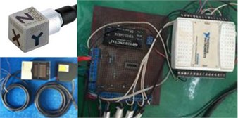
During the test, the uneven road disturbance excitation was acted on the wheel through hydraulic servo system (Fig. 11). The date of disturbance excitation was obtained through numerical simulation. Because that the proposed control strategy is essentially a kind of speed feedback control, so the displacement sensor was utilized to get the suspension dynamic deflection and dynamic velocity. Besides, an accelerometer was used to get the response of sprung mass (Fig. 12).
Table 1The main parameters of the bench
Suspension parameters | Value |
Sprung mass (kg) | 400 |
Unsprung mass (kg) | 50 |
Spring stiffness (N/m) | 15000 |
Tire Stiffness (N/m) | 100000 |
Fig. 10The test rig of quarter car model
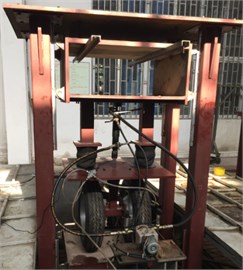
Fig. 11The electro-hydraulic servo system
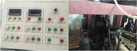
Fig. 12The sensors and the data acquisition
6.1. Bump excitation
An isolated bump, with relatively short duration and high intensity, in an otherwise smooth road surface is used. The corresponding ground displacement for the wheel is represented as:
where and are the height and the length of the bump respectively. Assume 0.1 m, 5 m, and the vehicle forward velocity as 20 m/s. The vibration acceleration of sprung mass is shown in Fig. 13.
It can be seen from the comparison, in this bump pavement excitation, through the NPC control, the maximum value of the sprung mass vibration acceleration is improved by 34.23 % (from the original –5.853 m/s2 to –3.849 m/s2).
6.2. Random road excitation
The road excitation is a primary external input for any suspension system. The random road profile is generated by Gaussian white noise passing through a first order filter [20] in this study:
where: is the vehicle speed; is the zero-mean Gaussian white noise input with intensity 1 in time domain; is the low cut-off frequency, 0.1 Hz hereby; and is the road roughness coefficient, whose geometric mean values are listed in Table 2. In this paper, 256×10-6.
Fig. 13Acceleration curve of sprung mass
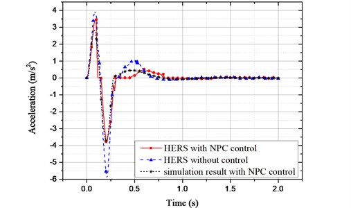
Table 2Classification of road roughness
Road level | Geometric mean value of / (10-6 m3) |
A | 16 |
B | 64 |
C | 256 |
D | 1024 |
It is known from Eq. (43) that correlates closely with the vehicle velocity. The velocity is set as 20 m/s in this study. The vibration acceleration of sprung mass is shown in Fig. 14.
As can be seen from Fig. 13, the sprung mass vibration acceleration is improved significantly with NPC control. The root mean square (RMS) value of sprung mass vibration acceleration is calculated as 1.592 m/s2 without control. While it is improved to 0.543 m/s2 with the proposed controller. It is improved by 65.9 %.
Fig. 14Acceleration curve of sprung mass
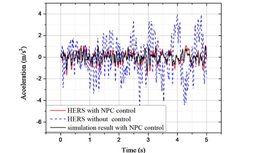
Both on bump excitation and random road excitation, the comparison between the experimental test and the numerical simulation was conducted. The maximum error is 0.4752 m/s2 on bump excitation. And the error of RMS is 0.102 m/s2 on random road excitation. Owing to the error of data acquisition and hysteresis of NPC controller, the simulation results appear to be better than the actual test results. But the overall tendency of test result is consistent with numerical simulation.
6.3. Control of optimal load current
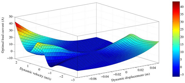
According to the control law in part four, the optimal control current is summarized. The optimal control current can be expressed as a function of suspension dynamic deflection and dynamic velocity through the controller algorithm. From the above experimental results, the optimal control load current related to suspension dynamic deflection and dynamic velocity is obtained, as shown in Fig. 15.
The graph displays the relationship between the optimal current and suspension dynamic deflection and dynamic speed. What’s more, the suspension dynamic deflection and dynamic speed can be conveniently obtained with sensors directly. Thus, the optimal load current could be given more quickly according to the three-dimensional map. It is important to improve the sensitivity of HERS control.
Fig. 15The optimal load current
7. Conclusions
Based on the working principle of HESA, the damping force composition of HESA is analyzed and deduced in this study. The composition of HESA damping force indicates that it can be divided into two parts. One is the uncontrollable part associated with the road excitation, the other is the adjustable part related to the electronic load. Through the experiments and piecewise fitting, the mathematical model of HESA damping force is obtained. Also, the reliability of the model is verified by test results.
Combined with the characteristics of HESA damping force model, the net power control (NPC) algorithm is proposed for the purpose of minimizing the vibration of sprung mass. The control law of optimal electronic load current is stated detailly. Also, the HERS bench test was carried out to verify the feasibility of NPC. The results of bump and random road excitation indicate that the HERS with NPC controller can effectively improve the vibration of sprung mass.
Through the proposed NPC control method, the control of HERS is realized, which makes it possible that the HERS system can act a role of semi-active suspension with variable damping. However, the proposed NPC control law is only aiming at the minimum vibration of the vehicle body. The energy recovery efficiency, the handling stability are not taken into consideration in this paper. These are also the following wok that should be studied.
References
-
Suda Y., Nakadai S., Nakano K. Hybrid suspension system with skyhook control and energy regeneration (development of self-powered active suspension). Vehicle system dynamics, Vol. 29, Issue S1, 1998, p. 619-634.
-
Nakano K., Yoshihiro S. U. D. A., Nakadai S., Koike Y. Anti-rolling system for ships with self-powered active control. JSME International Journal Series C Mechanical Systems, Machine Elements and Manufacturing, Vol. 44, Issue 3, 2001, p. 587-593.
-
Nakano K., Suda Y., Nakadai S. Self-powered active vibration control using a single electric actuator. Journal of Sound and Vibration, Vol. 260, Issue 2, 2003, p. 213-235.
-
Suda Y., Shiiba T., Hio K., Kawamoto Y., Kondo T., Yamagata H. Study on electromagnetic damper for automobiles with nonlinear damping force characteristics: (Road test and theoretical analysis). Vehicle System Dynamics, Vol. 41, 2004, p. 637-646.
-
Kawamoto Y., Suda Y., Inoue H., Kondo T. Electro-mechanical suspension system considering energy consumption and vehicle manoeuvre. Vehicle System Dynamics, Vol. 46, Issue S1, 2008, p. 1053-1063.
-
Kowal J., Pluta J., Konieczny J., Kot A. Energy recovering in active vibration isolation system-results of experimental research. Journal of Vibration and Control, Vol. 14, Issue 7, 2008, p. 1075-1088.
-
Ebrahimi B., Khamesee M. B., Golnaraghi F. Eddy current damper feasibility in automobile suspension: modeling, simulation and testing. Smart Materials and Structures, Vol. 18, 2009, https://doi.org/10.1088/0964-1726/18/1/015017.
-
Ebrahimi B., Bolandhemmat H., Khamesee M. B., Golnaraghi F. A hybrid electromagnetic shock absorber for active vehicle suspension. Vehicle System Dynamics, Vol. 49, Issue 1, 2011, p. 311-332.
-
David S. B., and Bobrovsky B. Z. Actively controlled vehicle suspension with energy regeneration capabilities. Vehicle System Dynamics, Vol. 49, Issue 6, 2011, p. 833-854.
-
Li Z., Zuo L., Luhrs G., Lin L., Qin Y. X. Electromagnetic energy-harvesting shock absorbers: design, modeling, and road tests. IEEE Transactions on Vehicular Technology, Vol. 62, Issue 3, 2013, p. 1065-1074.
-
Sabzehgar R., Maravandi A., Moallem M. Energy regenerative suspension using an algebraic screw linkage mechanism. IEEE/ASME Transactions on Mechatronics, Vol. 99, 2014, p. 1-9.
-
Suda Y., Shiiba T. A new hybrid suspension system with active control and energy regeneration. Vehicle System Dynamics, Vol. 25, Issue S1, 1996, p. 641-654.
-
Gysen B. L., Van der Sande T. P., Paulides J. J., Lomonova E. Efficiency of a regenerative direct-drive electromagnetic active suspension. IEEE Transactions on Vehicular Technology, Vol. 60, Issue 4, 2011, p. 1384-1393.
-
Di Iorio F., Casavola A. A multiobjective H∞ control strategy for energy harvesting while damping for regenerative vehicle suspension systems. American Control Conference (ACC), 2012.
-
Roshan Y. M., Moallem M. Control of a regenerative suspension system utilizing a three-phase bidirectional converter. Industrial Electronics Society, IECON 2014-40th Annual Conference of the IEEE, 2014.
-
Sharp R. S., Crolla D. A. Road vehicle suspension system design-a review. Vehicle System Dynamics, Vol. 16, Issue 3, 1987, p. 167-192.
-
Fang Z., Guo X., Xu L., Zhang H. Experimental study of damping and energy regeneration characteristics of a hydraulic electromagnetic shock absorber. Advances in Mechanical Engineering, 2013, https://doi.org/10.1155/2013/943528
-
Sammier D., Sename O., Dugard L. Skyhook and H∞ control of semi-active suspensions: some practical aspects. Vehicle System Dynamics, Vol. 39, Issue 4, 2003, p. 279-308.
-
Priyandoko G., Mailah M., Jamaluddin H. Vehicle active suspension system using skyhook adaptive neuro active force control. Mechanical Systems and Signal Processing, Vol. 23, Issue 3, 2009, p. 855-868.
-
Kaldas M., Henze R., Küçükay F. Improvement of heavy vehicles ride and braking performance via combined suspension and braking systems control. SAE International Journal of Materials and Manufacturing, Vol. 4, Issue 1, 2011, p. 535-552.
About this article

The authors gratefully acknowledge the National Natural Science Foundation of China (General Programs: Grant No. 5167052377 and Grant No. 51305314), and Wanxiang Group Technology Center.
