Abstract
In order to improve the downhill regenerative braking control effect of hybrid electric vehicle (HEV), this paper designs a downhill regenerative braking control method for hybrid electric vehicle (HEV). Firstly, the structures of regenerative braking system, auxiliary braking system and eddy current retarder (ECR) are analyzed. Secondly, the braking torque of ECR when HEV downhill braking is calculated. Then, the braking process of HEV is dynamically analyzed, and the braking force distribution constraint of HEV is realized according to the relevant laws and regulations. Finally, the downhill regenerative braking control of HEV is realized based on the braking force distribution coefficient. The results show that when the vehicle speed is up to 120 km·h, the speed control can still be completed within 2 s by using the proposed method, indicating a good regenerative braking effect.
Highlights
- Calculate the braking torque of eddy current retarder when the HEV is braking downhill
- Dynamic analysis of stress change during HEV braking
- HEV downhill regenerative braking control based on braking force distribution coefficient
1. Introduction
In recent years, the global average temperature is rising year by year, and the sea level is also rising. Some low-altitude areas are facing the danger of being submerged by sea water. In the face of oil security and ecological environment problems, the development of new energy vehicles (NEV) is of great significance. Chinese governments at all levels have given strong support to the development of new energy vehicles in terms of policies and regulations. More and more commercial vehicles use power batteries as power supplies. Using the power battery as the power supply of vehicles has the advantages of energy conservation, environmental protection, emission reduction, etc [1]. However, electric vehicles still have the disadvantages of short mileage and poor battery adaptability, which limit their wide application. Regenerative braking is one of the most important functions of hybrid electric vehicles. With the function of regenerative braking, the kinetic energy or potential energy of the vehicle can be converted into electric energy through the motor to achieve energy recovery and generate the braking force required by the vehicle. Therefore, regenerative braking can effectively reduce fuel consumption, pollutant emissions and brake pad wear of the whole vehicle [2]. In the braking process of HEV, there are motor braking, engine braking, braking friction braking and combined braking modes. Therefore, it is necessary to study the braking energy distribution strategy under different braking conditions to obtain the optimal distribution law of motor braking force, engine braking force and braking force [3]. Hybrid electric vehicle (HEV) is a complex system engineering, the manufacturing of which requires the collaboration of various fields such as electronics, machinery, automotive, chemistry, control and so on. Based on this, the research and development of HEV is a complex integration process of technologies. In this blue ocean of automotive hybrid vehicle manufacturing, the designers are not only given a wide design space, but also face difficulties in determining the best vehicle scheme and achieving design goals. In order to improve the economic performance of electric vehicles and expand their driving range, it is important to study the downhill regenerative braking control method of HEVs.
LV et al. [4] proposed a cab-b braking control method for vehicles controlled by power centralized EMUs. Based on the theory of traditional hydraulic braking system, the maximum energy of regenerative braking of HEVs is obtained through genetic algorithm iteration, and the front and rear ideal braking force distributions under ECE braking law are analyzed. Based on the braking force analysis of front drive vehicles, the existing typical regenerative braking strategies are analyzed so as to formulate a reasonable distribution of braking force, consider the system constraints, and conduct vehicle modeling and simulation under typical mine braking conditions. This method can improve the braking safety performance, but the vehicle speed control takes a long time. Meng et al. [5] put forward the regenerative braking control method of rear-drive pure electric vehicle. By analyzing the safety distribution area of braking force, the distribution area of braking force in ISIGHT software is optimized, the optimal distribution interval is obtained, and a new regenerative braking control strategy is proposed. The whole vehicle model of electric vehicle is established in AVL cruise, the regenerative braking control strategy model is established in MATLAB/Simulink, and the joint simulation is carried out under different braking intensity conditions. This method can effectively reduce the energy loss of the power system, but the downhill regenerative braking effect of HEV is poor.
Therefore, a regenerative braking control method for hybrid electric vehicle (HEV) is proposed. The braking torque of eddy current retarder is calculated during the downhill braking process of HEV, and the braking process of HEV is dynamically analyzed. The downhill regenerative braking control of HEV is realized according to the braking force distribution coefficient. The feasibility of the design method is verified by experiments.
2. Regenerative braking system of hybrid electric vehicle
2.1. Structure of regenerative braking system
Regenerative braking system is closely related to the configuration of the compound braking system. The regenerative braking system mainly consists of driving motor, power battery and controller. The working state of the driving motor can be divided into four types, including forward driving state, reverse driving state, forward braking state and reverse braking state [6]. When braking, the driving motor is transformed into a generator to transform part of the kinetic energy of the vehicle braking into electric energy and store it in the power battery. When driving, the motor is in the driving mode to convert the electric energy in the power battery into mechanical energy.
Fig. 1Structure of regenerative braking system
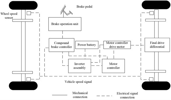
In the figure, the wheel speed sensor and braking operation unit are used as signal acquisition units to collect wheel speed signals and brake pedal opening signals, respectively, and transmit the collected signals to the composite braking controller. The composite braking controller and motor controller are used as control units to control the braking torque of the driving motor. The inverter assembly includes DC/AC inverter and DC/DC converter. The DC/AC inverter transforms the high-voltage DC power of the power battery into high-voltage AC power for the driving motor, and the DC/DC converter converts the high-voltage DC power into low-voltage DC power for the control unit [7]. The drive motor is mechanically connected with the main reducer. When the vehicle is braking, the composite braking controller selects the braking mode in line with the wheel speed signal, the SOC (System Operation Control) signal of the battery and the brake pedal signal. If the collected signal meets the requirements of regenerative braking, the motor controller controls the motor to be in the forward braking state, and then the alternating current generated by the motor is converted into DC through the setting of the inverter assembly and transmitted to the power battery.
Pure electric commercial vehicles need continuous braking to avoid stall under long downhill conditions. When the vehicle brake is braked for a long time, a large amount of heat will be generated between the brake shoe and the friction plate of the brake drum, which will cause the heat recession of the brake and affect the braking safety of the vehicle. When the driving motor is involved in the braking as a generator, it is also necessary to determine whether to recover the braking energy according to the charging state of the power battery. Therefore, under long downhill conditions, it is necessary to determine whether the regenerative braking mode is involved in braking [8-12]. To avoid thermal decay and overcharge of power battery, eddy current retarder needs to participate in vehicle braking under long downhill conditions.
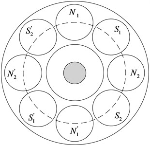
The main structure of eddy current retarder includes front and rear rotors and stator, as shown in Fig. 2. The front and rear rotor discs of the ECR are fixedly connected through the rotor shaft. When the retarder is mounted in series on the derailleur shaft, the speed of the front and rear rotor disks is the same and equal to the speed of the derailleur shaft. Between the two rotor discs, there is a stator mounted on the rotor shaft through bearings, with air gap existing between the stator and the rotor disc. As shown in Fig. 3, eight excitation coils are evenly distributed in the circumferential direction of the stator in turn. When the eddy current retarder works, the magnetic poles of two adjacent excitation coils are opposite.
Fig. 2Structure of Eddy current retarder
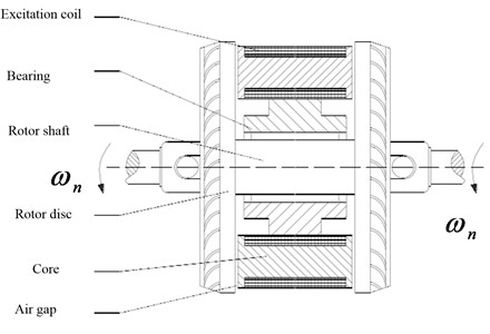
Fig. 3Magnetic pole distribution of excitation coil
3. Calculation of braking torque of ECR
The instantaneous power of eddy current in the cylindrical area where eddy current is generated in the rotor disk can be expressed as:
where represents the magnetic induction intensity and represents the distance between the axes of two adjacent excitation coils on the circumference with radius . is the resistance of the cylindrical ring. is the induced electromotive force generated on the rotor disk [13]. is the bandwidth of the cylindrical ring, represents the radius of the cylindrical ring, is the height of the cylindrical ring, and is the resistivity of the rotor disk material (Ω·m).
Then the instantaneous power of the whole cylinder can be calculated according to Eq. (2):
If the rotor disk turns a group of excitation coils for one cycle, the average value of instantaneous power in one cycle is:
Therefore, the braking force generated by a group of excitation coils on a single rotor disc is:
Thus, the total braking force generated by the excitation coil on the stator to the front and rear rotor discs is:
where is the relative permeability of the rotor disk material, , is the vacuum permeability of the rotor disk (H/m), and is the permeability of the rotor disk material, where . is the effective value of excitation current (A).
Then the braking torque of eddy current retarder is:
Table 1Parameters of AX5100 eddy current retarder
Parameter name | Parameter value | Parameter name | Parameter value |
Torque (N·m) | 1000 | Maximum current (A) | 105 |
Quality (kg) | 130 | Applicable vehicle weight (t) | 8-15 |
Stator mass (kg) | 80 | Installation mode | Drive shaft center |
Rotor mass (kg) | 50 | Overall dimension (mm) Length/width/shaft length | 416/416/250 |
Moment of inertia (kg/m2) | 1.2 |
For the talema AX5100 eddy current retarder studied in this paper, 0.19 m, resistivity of rotor disk material 9.78×10⁻⁸ Ω∙m, number of turns 320, air gap 1.2 mm, relative permeability 200, see Table 1 for other parameters.
By analyzing the working principle of ECR and calculating its braking torque, the relationship between braking torque and speed of eddy current retarder is obtained [14].
So far, the reconstruction design of the traditional commercial vehicle drive system and composite braking system has been completed. Due to the changes of the transmission system and braking system of the prototype, some parameters of the whole vehicle are changed.
Table 2Partial parameters of commercial pure electric vehicles
Vehicle parameters | Parameter value | Vehicle parameters | Parameter value |
Curb/full load mass (kg) | 6280/12240 | Windward area (m2) | 7 |
Length/width/height (mm) | 9000/2496/3105 | Rotating mass conversion factor | 1.05 |
Wheelbase (mm) | 5120 | Approach/departure angle (°) | 19/12 |
Wheel radius (mm) | 510 | Front suspension/rear suspension (mm) | 1430/2450 |
Drag coefficient | 0.56 | Front/rear track (mm) | 1930/1800 |
4. Control method of downhill regenerative braking
4.1. Dynamic analysis of braking process
The braking force of HEV is consisted of rolling resistance, air resistance, ramp resistance, motor regenerative braking force and brake braking force.
The braking force of the whole vehicle braking system is basically equal to the braking force of the whole vehicle braking system minus the driving resistance. The HEV with front drive is the research object. The front wheel includes the motor braking force [15]. Thus:
where represents the braking force of HEV system (N). represents the braking force on the front axle of HEV (N). represents the braking force on the rear axle of HEV (N). represents the regenerative braking force provided by the motor (N). represents the braking force of front wheel brake of HEV (N). After the braking force of the whole vehicle braking system acts on the wheels, the external force required to decelerate the vehicle braking is finally provided by the ground, that is, the ground braking force. The size is determined by the friction of two friction pairs. First, the torque of the braking force of the braking system acting on the wheels is the system braking torque . The second is the friction between the tire and the ground, that is, the ground braking force .
System braking force is:
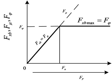
Fig. 4 shows that when braking, if only the wheel state is rolling and locked, when the pedal force is small, the system braking force is small, and the ground braking force can overcome the system braking force and keep the wheel rotating. At this point, the ground braking force is equal to the system braking force, which increases in direct proportion with the increase of pedal force, but its maximum value does not exceed the ground adhesion:
where is the ground braking force (), represents the ground adhesion coefficient.
Fig. 4Relationship among system braking force, ground braking force and pedal force
4.2. Downhill regenerative braking control of front and rear wheels of vehicle
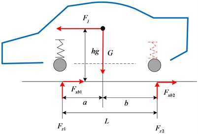
In the braking state, the regenerative braking switches the motor into a generator, uses the inertia of the vehicle to drive the rotation of motor rotor and generate reverse torque, and converts part of the kinetic energy or potential energy into electrical energy for storage or utilization. Therefore, this is an energy recovery process. When the car is braked, if the front wheels lock first, the car will lose steering ability; if the rear wheels lock up first, the car will slip under the action of slight lateral force, which is a dangerous working condition; locking the front and rear wheels simultaneously is the most ideal braking state. Fig. 5 shows the force analysis diagram of the vehicle during braking. Ignoring the coupling torque of rolling resistance, inertia torque and air resistance generated during the deceleration of rotating mass of the vehicle, the following results can be obtained according to the torque balance:
where represents the braking strength; denotes the ground normal reaction force on the front wheel (N). denotes the ground normal reaction force on the rear wheel (N). denotes the height of center of gravity (m). represents wheelbase (m). represents the distance from the center of gravity to the front axle (m); represents the distance from the center of gravity to the rear axle (m).
Fig. 5Stress diagram of vehicle during braking
When the vehicle is braked, the front and rear wheels can be locked up simultaneously when the sum of the braking forces on the front and rear axles of the vehicle is equal to the adhesion, and the braking forces on the front and rear axles are equal to their respective adhesion. Then we have:
Substituting Eq. (12) into Eq. (11) yields:
On this basis, the ideal braking force distribution curve of front and rear wheels can be obtained. In practice, it is difficult to achieve a distribution according to a braking force distribution curve. Most vehicles have a fixed braking force ratio between the front and rear wheels.
is normally used to represent the braking force distribution coefficient:
To avoid the locking and sideslip of rear wheel, the front and rear braking force distribution line of the vehicle ( Line) should always be below the curve. To reduce the chance of losing steering ability due to front wheel locking and improve the adhesion efficiency, , the line should be approaching to line .
According to the braking force distribution coefficient , the ground braking force distribution curve of front and rear wheels of HEV can be obtained.
Fig. 6Actual braking force distribution of front and rear wheels of HEV
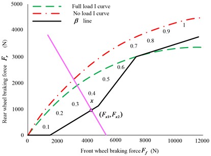
It can be seen more intuitively from Figure 6 that when the braking intensity is less than 0.1, the front wheels provide all the braking force, and the rear wheel braking force is zero. With the increase of braking intensity, the rear wheels participate in the braking process, and the front and rear wheels brake together according to the braking force distribution of the front and rear wheels of the hybrid vehicle. Therefore, the downhill regenerative braking control of HEV is realized.
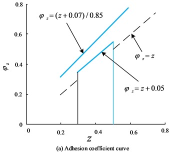
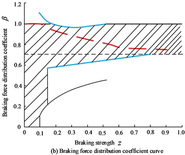
According to the provisions of “structure, performance and test methods of automobile braking system” (GB 12676-1999) on the distribution of car braking force, as shown in Fig. 7(a), when = 0.2-0.8, the front axle utilization adhesion coefficient curve (UACC) shall be above the rear axle UACC, and ; when 0.3~0.5, the rear axle UACC is allowed to be above the front axle utilization curve under the condition that the rear axle UACC does not exceed the straight line, then there is .
Fig. 7Braking force distribution of hybrid vehicles required by regulations
a)
b)
The shaded part in Fig. 7(b) shows the distribution of braking coefficient calculated according to the requirements of the regulation . The dotted line is the value of the braking force distribution coefficient of the front and rear wheels. When the braking strength is small, gradually decreases with the increase of braking intensity, in order to reduce the possibility of front wheel locking and improve the braking efficiency.
5. Experiment
5.1. Experimental design
In view of the many downhill regenerative braking functions of HEVs in this paper, vehicle deceleration control effect and downhill speed control efficiency are verified in the simulation.
5.2. Experimental result
5.2.1. Simulation and analysis of sliding condition
Based on MATLAB/Simulink, CarSim and AMESim, a joint simulation platform of hydraulic braking system is built in this paper. The pressure estimation and control effect of active braking control strategy are verified by off-line simulation, and the overall framework of joint simulation is established. According to the control strategy of MATLAB/Simulink, the output braking system pressure control signal is calculated, transmitted and applied on the AMESim hydraulic braking system model through the interface between AMESim and MATLAB/Simulink. Then the pressure of output master cylinder and each wheel cylinder from the AMESim model is calculated and used as the CarSim vehicle model to realize the braking control of the vehicle. The proposed braking force distribution strategy and the established model are adopted for simulation in order to realize the expected goals:
A. Maintain the deceleration when sliding with engine braking;
B. During sliding deceleration, the motor shall be used first to give full play to the braking potential of the motor. When the motor fails to meet the requirements, engine braking and friction braking shall be engaged.
The simulation of taxiing condition is conducted by taking the initial speed of 50 km/h and combining the results shown in Fig. 8. The fixed step simulation is adopted, in which the simulation step is set to 0.01 s, and the solver adopts ode4 (Runge Kutta) solver. The pavement adhesion coefficient is 0.7 and the initial SOC value is 0.7.
Fig. 8Simulation results of taxiing at initial speed of 50 km/h
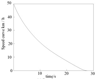
a) Speed curve
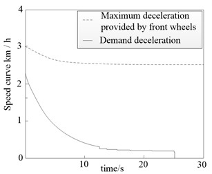
b) Front wheel deceleration
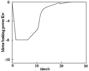
c) Motor braking power curve
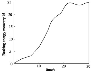
d) Braking energy recovery curve
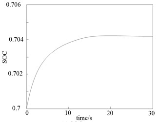
e) SOC curve
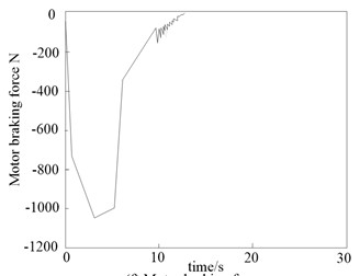
f) Motor braking force curve
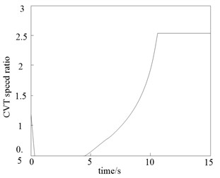
g) CVT speed ratio
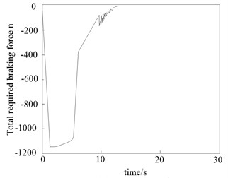
h) Total demand braking force curve
Fig. 8 shows that the vehicle model and braking force distribution strategy can well simulate the speed of engine braking during taxiing, so that the hybrid vehicle in this paper exhibits the same deceleration as the traditional fuel vehicle during taxiing, so as to achieve the first expected goal. During taxiing, the maximum deceleration of the front wheel is always greater than the required deceleration, and the braking force during taxiing can be provided by the front wheels. Since the total required braking force is large in the initial stage of taxiing (2 s-7 s), the motor cannot provide all braking force, and the excess braking force is offered by the engine braking through the clutch between the engine and the motor. The motor generates electricity at maximum power. When the vehicle speed is further reduced, the total required braking force is reduced and the motor alone provides all braking force. The above operation results show that the instantaneous optimal control method proposed in this paper has better downhill regenerative braking effect of HEV.
5.2.2. Downhill speed control efficiency of vehicle on long slope
In order to evaluate the downhill speed control efficiency on long slope, the actual simulation experiment was conducted. The test was conducted on a closed long slope, and the speed was set to micro, 40, 60, 80, 100, and 120, respectively. Under the above speed limits, the speed control efficiency of the same type of vehicles with different methods was analyzed. The statistical evaluation results of the time consumption of downhill speed control using reference [4], reference [5], and the proposed method are shown in Table 3.
Table 3Downhill speed control time of vehicle on long slope
Speed (km·h) | Downhill speed control time on long slope/s | ||
Reference [4] method | Reference [5] method | Paper method | |
20 | 3.6 | 3.8 | 0.1 |
40 | 5.8 | 6.2 | 0.3 |
60 | 8.2 | 6.6 | 0.5 |
80 | 12.8 | 8.2 | 0.8 |
100 | 18.3 | 10.6 | 1.3 |
120 | 15.6 | 12.1 | 1.8 |
By analyzing Table 3, it can be seen that there are differences in the downhill speed control time of vehicle on long slope under different methods. When the vehicle running speed is 20 km·h, the downhill speed control time of Reference [4] method, Reference [5] method and the proposed method is 3.6 s, 3.8 s, and 0.1 s, respectively; When the speed is 60km·h, the downhill speed control time of Reference [4] method, Reference [5] method and the proposed method is 8.2 s, 6.6 s, and 0.5 s, respectively; When the vehicle running speed is 120 km·h, the downhill speed control time of Reference [4] method, Reference [5] method and the proposed method is 15.6 s, 12.1 s, and 1.8 s, respectively. When the vehicle speed is as high as 120 km·h, the method in this paper can still realize downhill speed control within 2 s with improved safety.
6. Conclusions
This paper presents a downhill regenerative braking control method for HEV, analyzes the structure of the regenerative braking system, calculates the braking torque of the eddy current reducer during the downhill braking process of HEV, analyzes the dynamics of the braking process of HEV, and realizes the downhill regenerative braking control of HEV according to the braking force distribution coefficient. The experimental results show that the proposed method has a good effect on the downhill regenerative braking of HEV system, and has certain application value.
References
-
Z. C. Chen, B. Zhu, J. Zhao, J. Wu, D. J. Song, and J. P. Du, “Electro hydraulic distribution control strategy of regenerative braking based on adjustable reservoir,” Automotive Engineering, Vol. 44, pp. 239–246, 2022, https://doi.org/10.19562/j.chinasae.qcgc.2022.02.011
-
J. X. Liu, L. Wang, and Z. F. Liu, “Regenerative braking system based on fuzzy logic control for 4WD electric wheel vehicle,” Mechanical Design and Manufacturing, Vol. 12, pp. 164–168, 2021, https://doi.org/10.19356/j.cnki.1001-3997.2021.12.027
-
Y. Zhang, S. Xiao, and B. H. Wang, “Anti rollover control of four-wheel steering commercial vehicle based on differential braking,” Journal of Hubei Institute of Automotive Technology, Vol. 36, pp. 7–11, 2020, https://doi.org/10.3969/j.issn.1008-5483.2022.01.002
-
X. Lv, H. A. Hou, J. Xia, X. J. Ren, and M. S. Zhang, “Cab-b brake control system for power centralized EMU,” Railway Rolling Stock, Vol. 58, No. 12, pp. 5–17, 2020, https://doi.org/10.3969/j.issn.1002-7602.2020.12.005
-
Z. W. Meng, T. Z. Zhang, H. X. Zhang, Q. H. Zhao, H. X. Yin, and D. P. Hou, “Research on regenerative braking control strategy of rear drive pure electric vehicle,” Journal of Qingdao University (Engineering Technology Edition), Vol. 35, pp. 65–71, 2020, https://doi.org/10.13306/j.1006-9798.2020.01.012
-
M. Song, R. Li, and B. Wu, “Intelligent control method for traffic flow at urban intersection based on vehicle networking,” International Journal of Information Systems and Change Management, Vol. 12, No. 1, p. 35, 2020, https://doi.org/10.1504/ijiscm.2020.10034334
-
H. C. Lan, Z. Y. Ma, X. B. Li, and H. X. Que, “Long downhill combined braking control strategy of electric commercial vehicle based on dynamic programming,” Journal of Northwest University (Natural Science Edition), Vol. 50, No. 6, pp. 987–995, 2020, https://doi.org/10.16152/j.cnki.xdxbzr.2020-06-015
-
Z. Q. Li and K. Yan, “Fast generalized predictive control of braking process of high-speed EMU,” Computer Simulation, Vol. 37, No. 6, pp. 104–110, 2020, https://doi.org/10.3969/j.issn.1006-9348.2020.06.023
-
G. H. Fang, B. Zeng, X. D. Hu, H. C. Wang, X. Gao, and Z. Y. Yang, “Control strategy of regenerative braking energy recovery system of hybrid electric mining vehicle,” Machine tools and hydraulics, Vol. 48, pp. 135–140, 2020, https://doi.org/10.3969/j.issn.1001-3881.2020.01.028
-
Q. D. Wang, Y. X. Li, W. W. Chen, L. F. Zhao, and Y. H. Xie, “Research on emergency obstacle avoidance of intelligent vehicle based on brake steering cooperative control,” Automotive Engineering, Vol. 41, No. 4, pp. 395–403, 2019, https://doi.org/10.19562/j.chinasae.qcgc.2019.04.006
-
X. Xu, J. Mi, C. Y. Wen, F. Wang, S. D. Ma, and T. Tao, “Synchronous braking control of trailer RV based on hook force model,” Journal of Beijing University of Aeronautics and Astronautics, Vol. 45, No. 7, pp. 1283–1293, 2019, https://doi.org/10.13700/j.bh.1001-5965.2018.0658
-
F. P. Luo, H. Y. Sun, Q. Wang, L. Zhang, and H. R. Shu, “Research on braking control technology of high speed EMU,” Electromechanical Product Development and Innovation, Vol. 34, No. 3, pp. 97–100, 2021, https://doi.org/10.3969/j.issn.1002-6673.2021.03.032
-
J. B. Song and C. Liang, “Cooperative control of dual electro-hydraulic regenerative braking system of rear wheel drive electric vehicle,” Chinese Journal of Construction Machinery, Vol. 19, No. 2, pp. 131–135, 2021, https://doi.org/10.15999/j.cnki.311926.2021.02.007
-
S. Z. Yuan, J. Li, and Z. Zhou, “Research on braking control strategy of two axle four-wheel drive electric vehicle based on braking intention recognition,” Journal of Hefei University of Technology (Natural Science Edition), Vol. 45, No. 2, pp. 158–164, 2022, https://doi.org/10.3969/j.issn.1003-5060.2022.02.003
-
S. H. Wu, B. Wang, X. Z. Tang, and Q. P. Wen, “Regenerative braking control strategy of hybrid electric vehicle based on safety correction coefficient,” Mechanical Design, Vol. 37, No. 2, pp. 21–31, 2020, https://doi.org/10.13841/j.cnki.jxsj.2020.02.003
Cited by
About this article

The authors have not disclosed any funding.
The datasets generated during and/or analyzed during the current study are available from the corresponding author on reasonable request.
The authors declare that they have no conflict of interest.
