Abstract
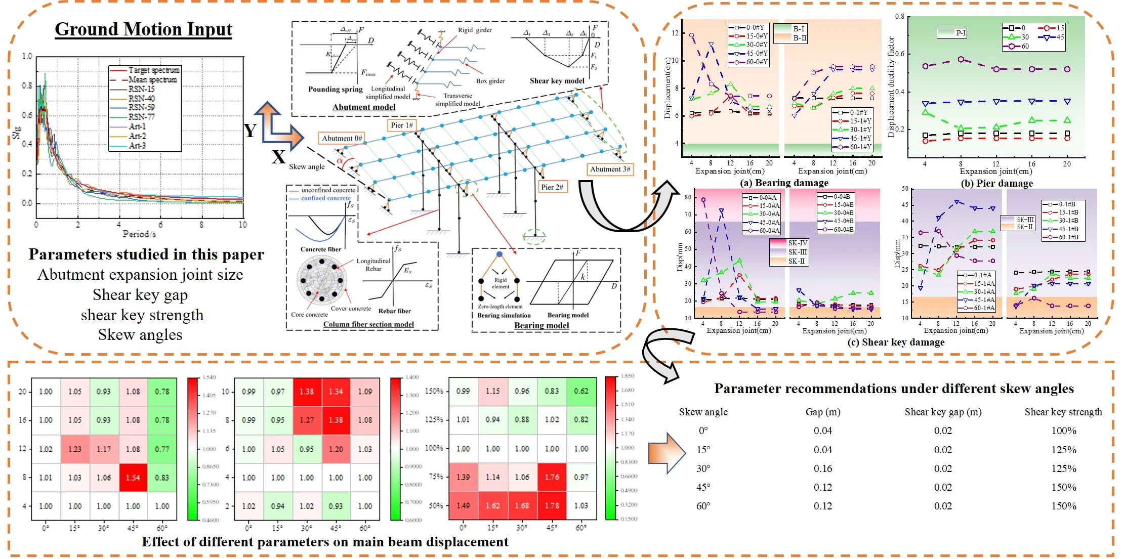
A finite element model is created using OpenSees software to perform a time history analysis in order to analyze the seismic response law of a skew bridge and the damage volume of its key components, using a typical 3×20 m skew continuous girder bridge as an example. The seismic response of the skew continuous girder bridge under various factors such as the size of the abutment expansion joint, shear key gap, and shear key strength is studied then the damage rate is assessed for the bearing, shear key, and pier. The research results show that under the action of earthquake ground motion with 0.3 g PGA, the seismic force transmitted to the pier is small, and the pier is elastic owing to the sliding of the bearing, but the damage degree of the shear key is larger than that of the bearing and pier. The impact increases the rotation effect of the main beam in the direction of off acute angle, resulting in a greater damage to the shear key at the acute angle than that at the obtuse angle. The damage of bearing and shear key increases and then decreases with the increasing of expansion joint, and the larger the skew angle is, the smaller the expansion joint will be corresponding to the maximum displacement of bearing and shear key. With the increase of the shear key gap, the deformation limitation effect of the shear key on the main beam decreases significantly, resulting in a linear increase in the bearing slip, which increases the risk of the main beam subsidence. With the increase of the shear key strength, the bearing and shear key damage decreases greatly at first, and then increases slightly. However, the pier damage increases obviously. In an area with a high risk of earthquake, it is recommended that the shear key can be a “fuse element”. For any oblique angle, the shear key gap can be reduced to 2 cm, and the shear key strength can be increased to 125 % or 150 %. When the skew angle is between 30 and 60, the expansion joint size can be increased to 12 cm or 16 cm.
Highlights
- The main beam rotates in the direction of the acute angle, and the damage of the shear key at the acute angle is greater than that at the obtuse angle.
- When the main beam collides with the abutment, the collision will increase the plane rotation effect of the main beam. With an increase in the expansion joint, the damage to the bearing and shear key initially rises and subsequently falls.
- Although the shear key gap increase can greatly reduce the damage to the shear key and the pier, the main beam deformation limiting effect is significantly diminished, leading to a linear growth of bearing slip and an increased danger of the main beam subsidence.
- The shear key is an important component to limit the excessive displacement of the main beam. In the strong vibration area, it is recommended to take the shear key as a "fuse element" and increase the overlapping length of abutment and pier for mitigating the risk of beam falling.
1. Introduction
Skew bridge is an excellent choice in meeting the special requirements of line linearity, which can optimize the line, save investment, improve social and economic benefits under specific circumstances. In the devastating earthquakes such as the 1971 San Fernando earthquake and the 1994 Northridge earthquake in the United States, the 2008 Wenchuan, China earthquake, and the 2010 Maule, Chile earthquake, it was found that skew bridges were seriously damaged [1-4]. In addition, the seismic damage of the skew bridges was more serious than that of the straight bridges, and the proportion of skew bridges with moderate damage was determined to be 62.2 % in the 2008 Wenchuan, China earthquake disaster survey, compared to just 11.3 % for straight bridges [3]. The severe longitudinal and lateral displacement of the main beam, along with the beam plane rotation, were the primary seismic damage indicators for the skew bridge in case of prior moderate-strong earthquakes, increasing the risk of beam falling [2, 5]. Further research into the mechanism causing the substantial seismic damage to the skew bridge is required considering the above-mentioned damage.
The second and third vibration models of the skew bridges are greatly affected by the skew angle, which provide mainly torsional vibration and lateral displacement, resulting in obvious coupling effect of longitudinal and lateral displacement of the main beam [6, 7]. Due to the large displacement of the main beam, there is a significant collision between the main beam, abutment, and shear key [8]. When the collision is not considered, the beam rotation is caused by the rotational vibration mode, and the maximum rotation angle increases with the increasing skew angle [9]. But if to consider the collision, it is possible to observe longitudinal and transverse collisions which aggravate the plane rotation of the main beam [10]. The analysis above showed that the main beam plane rotation was caused by the irregular geometry of the skew bridge and the collision. The main beam displacement is simultaneously limited to some extent by the abutment, adjacent span, and shear key [11, 12], but the seismic force delivered to the substructure is increased [13]. The collision causes a significant seismic displacement response, especially the response of bearing, abutment, and shear key, and it is necessary to increase the seismic response demand of shear keys under a strong earthquake [14, 15]. Based on the above researches, it becomes clear that the skew angle and the collision significantly affect the seismic response of the skew bridge, which need to be considered in a further analysis.
The seismic response of the skew bridge is also affected by the strength of the shear key, the size of abutment expansion joint, and the gap of the shear key [16, 17]. Thus, researchers have used a variety of comparative analytic techniques to examine the impact of these parameters on the seismic response. The finite element numerical analysis is the common method to establish a probabilistic seismic demand model and a vulnerability curve for the skew bridge [18, 19]. S.W. Wu et al. [20-22] studied the limit range of free rotation of the main beam of a bridge with or without expansion joints by a shaking table test, and verify the rationality of the finite element modeling. Additionally, the artificial neural network method is used to determine the relative importance of each uncertain parameter on the vulnerability curve of skew bridge piers [23]. Previous research mainly concentrated on the main girder's seismic response requirements, established a component vulnerability curve, and examined the impact of different parameters on the pier's vulnerability. However, it was rarely evaluated how relevant parameters affected the damage of important components through specific damage criteria, and how this affected the overall seismic performance of skew bridges.
In this paper, a refined finite element model of a typical 3×20 m continuous beam bridge is established through the OpenSees platform for a time history analysis with considering the bidirectional collision effect of the abutment and the shear key. The effect of abutment expansion joint size, shear key strength, and shear key gap on the seismic response of skew continuous beam bridges at various skew angles are examined in this research. According to the determined damage standard value, the damage evaluations of the bearing, shear key and pier column under different parameters are carried out, and the influence of different skew bridge parameters on the damage degree of key components is obtained. The seismic response of the skew bridge is simultaneously enhanced by obtaining the reasonable parameter configuration under various skew angles in accordance with the degree of damage to key components and the seismic response results of the skew bridge.
2. Finite element model of skew bridge
2.1. Overview of typical bridge and finite element model
This paper is based on a 3-span skew continuous girder bridge which is arranged as 3×20 m. The main beam is 1.2 m high and 23.5 m wide beam which is constructed of C50 concrete and composed of 4 pieces of prestressed small box girders. Two laminated rubber bearings are arranged under each small box girder. The ones located under the bearing of abutment 0# and 3# are GYZd250, and the one for the piers #1, 2# is GYZd350 [24]. The superstructure is composed of two 3-m high three-group columns constructed of C35 concrete with a circular cross-section of 1.5 m in diameter.
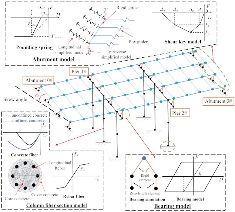
OpenSees platform is used to establish a full bridge analytical model [25], as shown in Fig. 1. The main beam is modeled simply according to the grillage method, and the longitudinal beam and the virtual cross beam are diagonally crossed into a grid, which is simulated by the elastic beam column element. Considering the sliding behavior of the laminated rubber bearing, the bearing constitutive model is a bilinear restoring force model. The bearing and main beam are connected by a rigid beam, so the bearing behavior can be simulated by the Zero-length element. Nonlinear beam column elements are used to simulate the column. Reinforcement, restrained concrete, and unrestrained concrete are all included in the fiber section. For concrete and reinforcement, respectively, the Mender constitutive model and the Pinto constitutive model are used. Without considering the interaction of the pile and soil, the column bottom is deemed to be consolidated. The seismic response of skew bridge is significantly influenced by the abutment and shear key. Five nonlinear springs in series with gap elements are used to simulate the passive earth pressure behind the abutment and the abutment gap in OpenSees [26, 27]. The strength of the shear key is ensured by concrete and reinforcement, and the force deformation relationship envelope curve can be simplified as four segment line with consideration of the rigidity degradation of the shear key. The elastic-perfectly plastic gap material and Zero-length element are added to the simulation to complete the picture.
Fig. 1Finite element analysis model
This paper focuses on the influence of the abutment expansion joint, shear key gap, and shear key strength on the damage of key components under different skew angles. The original design data of the expansion joint, shear key gap, and the maximum stress of the shear key are 0.04 m, 0.04 m, 1.25×10³ kN, respectively. When analyzing the influence of shear key strength on the seismic response of skew bridge, the shear key strength of the typical bridge is set as 100 %, which increases or decreases by 25 % for each condition. Under different skew angles, only one parameter is changed each time for the time history analysis, and the parameters are shown in Table 1.
Table 1Parameters of skew bridge
Parameters | Values |
Skew angle | 0°, 15°, 30°, 45°, 60° |
Expansion joint (cm) | 4, 8, 12,16,20 |
Shear key gap (cm) | 2,4,6,8,10 |
Shear key strength | 50 % (0.63×10³kN), 75 % (0.94×10³kN), 100 % (1.25×10³kN), 125 % (1.56×10³kN), 150 % (1.88×10³kN) |
2.2. Ground motion input
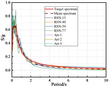
The target response spectrum is obtained based on the site conditions of the typical bridge and the design specification [26]. Three artificial seismic waves are generated with reference to the target response spectrum, and four natural ground motion recorded waves are selected from the Pacific Earthquake Engineering Center ground motion database, which are all adjusted to 0.3 g PGA, as shown in the Fig. 2. Without considering the vertical ground motion, the seismic waves are inputted along the and axes, and the average seismic response of the seven waves is then used for analysis and discussion.
Fig. 2Response spectra curves
3. Evaluation index of seismic response of members
3.1. Damage evaluation for laminated rubber bearing
In this paper, the bearing displacement is used as an evaluation parameter of bearing damage, referring to the damage evaluation of bearing, and the damage status and judgment criteria of the bearing are obtained, as shown in Table 2. represents the critical displacement of laminated rubber bearing; represents the distance from the edge of laminated rubber bearing to the edge of small box girder on the same side; represents the distance from the center line of laminated rubber bearing to the edge of small box girder; represents the distance from the outer edge of laminated rubber bearing to the inner edge of small box girder; represents the distance from the outer edge of laminated rubber bearing to the edge of bent cap.
The critical displacement is calculated according to the following Eq. (1) [26]:
where, is the friction coefficient of bearing equal to 0.30; is the vertical dead load reaction of the bearing; is the shear stiffness of laminated rubber bearing.
Table 2Damage degree and evaluation criteria for laminated rubber bearing
Damage degree | Description of damage degree | Evaluation criteria |
No damage (B-Ⅰ) | The bearing is elastic without sliding | |
Minor damage (B-Ⅱ) | The bearing slides and still is in contact with the superstructure. | |
Moderate damage (B-Ⅲ) | The bearing is slightly fallen off, but most of the bearing area is still in contact with the beam bottom. | |
Severe damage (B-Ⅳ) | The contact area between the bearing and beam bottom is less than half of the bearing area, and the bearing is in a semi void state. | |
Bearing subsidence (B-Ⅴ) | The bearing is completely separated from the upper structure, and the beam slides from the pad stone and bearing to the bent cap, close to the beam falling. | |
Dropped beam (B-Ⅵ) | If the bearing displacement exceeds the maximum lap length provided by the bent cap, the beam body will fall horizontally. |
Fig. 3Structure layout and dimension at laminated rubber bearing
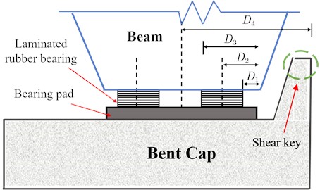
The structural layout and dimensions of the laminated rubber bearing in this paper are shown in Fig. 3, and the relevant parameters are calculated according to the actual dimensions of the typical bridge, as shown in Table 3.
Table 3Bearing damage parameter values
Damage parameters | |||||
Value (cm) | 7.50 | 22.56 | 41.06 | 59.56 | 109.75 |
3.2. Damage evaluation for shear key
The top displacement of the shear key is used as a parameter in this article to evaluate the damage degree of the reinforced concrete shear key. According to the research results of Megally and L. Q. Xu [27, 28], the constitutive model of the shear key consists of reinforcement part and concrete part, which can be simplified into a multi-segment line model.
Table 4Damage degree and evaluation criteria for reinforced concrete shear key
Damage degree | Description of damage degree | Evaluation criteria |
No damage (SK-Ⅰ) | There are small cracks at the junction between the inner side of the shear key and the bent cap, and the shear key is basically in a linear elastic state | |
Minor damage (SK-Ⅱ) | The initial small cracks are connected into a line and continue to develop below the syncline, forming a main crack, and part of the reinforcement yielding | |
Moderate damage (SK-Ⅲ) | The main crack runs through, the crack width increases continuously, the concrete begins to peel off, and new main cracks form and develop at the same time | |
Severe damage (SK-Ⅳ) | Several main cracks are cut through, the crack width is very large, the reinforced concrete is compacted, and the concrete is peeled off in a large range | |
Shear key damage (SK-Ⅴ) | The shear key is seriously displaced, and the reinforcement is broken; The shear key even falls off |
The damage grades and assessment criteria of reinforced concrete shear key are classified according to the simplified analysis model of reinforced concrete shear key, as indicated in Table 4. The force deformation envelope diagram of the shear key, as well as the detail diagram of concrete and reinforcement, are shown in Fig. 4, and the relevant specific parameters are listed in Table 5.
Fig. 4Shear key force deformation envelope
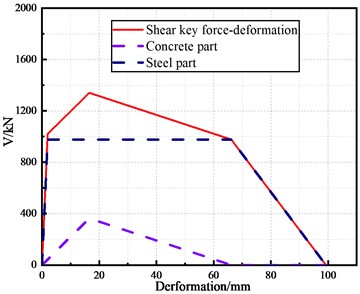
Table 5Shear key damage parameter values
Parameters | ||||
Deformation (mm) | 2.0 | 16.5 | 66.2 | 99.2 |
Shearing force (kN) | 1021.0 | 1340.0 | 977.4 | 0.0 |
3.3. Damage evaluation for pier
The displacement ductility coefficient of the pier, , is used as the reference index of pier damage in this paper [29]. The is defined in Eq. (2), and Table 6 shows the classification standard of the pier damage degree [30]. According to the pier damage criteria in Table 6, the displacement ductility coefficient of the pier is 1.0 when the reinforcement is yielding for the first time. Other parameters, which are shown in Table 7, can be obtained in a pushover analysis of the pier:
where, is the seismic displacement at the pier cap beam, is the displacement at the pier cap beam corresponding to the first yielding of the pier column reinforcement.
Table 6Damage degree and evaluation criteria for pier
Damage degree | Description of damage degree | Evaluation criteria |
No damage (P-Ⅰ) | The steel bar does not yield, and only slight cracks occur on the concrete surface | |
Minor damage (P-Ⅱ) | The steel bars yield, and the concrete surface cracks obviously | |
Moderate damage (P-Ⅲ) | Local plastic hinges begin to form, surface cracks expand, and local protective layer concrete begins to peel off | |
Severe damage (P-Ⅳ) | The plastic hinge is completely formed, forming a large width of crack, and the concrete in the whole plastic hinge area peels off | |
Complete damage (P-Ⅴ) | Longitudinal reinforcement yielding, reinforcement breaking, core concrete crushing |
Table 7Pier damage value
Damage parameters | ||||
Value | 1.00 | 1.12 | 3.10 | 6.91 |
4. Result analysis
4.1. Influence of expansion joint size on seismic response of skew bridge
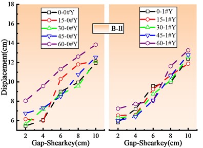
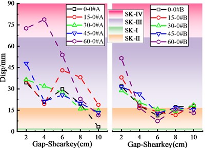
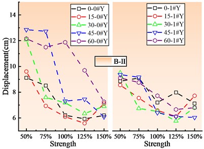
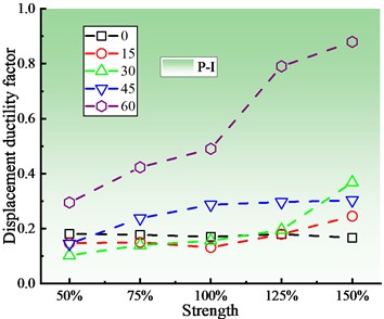
Fig. 5 shows the damage status of key components of skew bridge with different expansion joint sizes at the abutment according to the damage analysis results. Under the action of ground motion with 0.3 g PGA, the bearing is slightly damaged (B-Ⅱ), and sliding occurs. When the skew angle is within the range of 15° to 45°, the bearing displacement at abutment 0# increases first, then decreases and finally tends to be stable with the increase of expansion joint, and reaches the maximum displacement at 8 cm. The bearing displacement reduces and then tends to be stable when the skew angle is between 45° and 60°. However, the bearing displacement at pier 1# increases with the increase of expansion joint and then tends to be stable, and the stable displacement at abutment 1# is significantly greater than that at the abutment 0#. The pier is considered as having no-damage (P-I) when the displacement deformation coefficient of the pier basically remains constant.
The damage of the shear key is greater than that of the bearing and pier, and is mainly considered as having severe damage (SK-Ⅳ) and moderate damage (SK-Ⅲ). It is also found that the deformation of the shear key at the acute angle side is much greater than that at the obtuse angle side, which is consistent with the actual seismic damage of the skew bridge [3, 4]. The bearing displacement and the shear key deformation are consistent with the increasing expansion joint, and the smaller the expansion joint is, the more sensitive the deformation of the shear key will be as compared with the deformation change trend of the shear key. The deformation of the shear key at the acute angle side of abutment 0# is essentially the same as that at the obtuse angle, however the damage of the shear key at the pier 1# is significantly more than that at the obtuse angle side. S. W. Wu [12] also got the familiar results through shaking table test. When the expansion joint is large enough, the shear key deformation and deformation difference between acute angle side and obtuse angle side are relatively small.
Fig. 5Damage of key components of skew bridge with different expansion joints
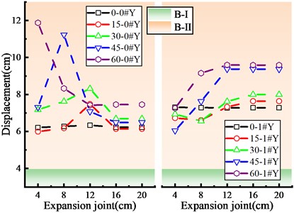
a) Bearing damage
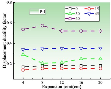
b) Pier damage
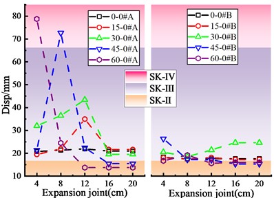
c) Shear key damage of abutment 0#
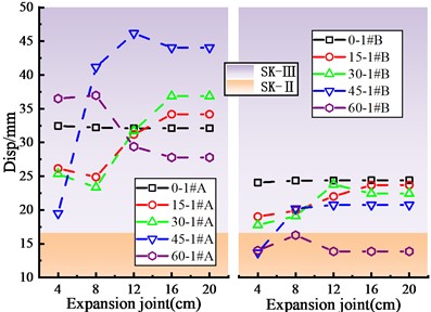
d) Shear key damage of pier 1#
In order to explore the damage mechanism of key components affected by the size of expansion joint, this paper extracts the end displacement of main beam under different sizes of expansion joint and the collision force between main beam and abutment with the 45° skew angle, as shown in Fig. 6(a-c). The longitudinal displacement at the end of the main beam increases and then tends to be stable with the increasing expansion joint, and the longitudinal displacement after stabilization shall be smaller than the expansion joint size. If so, it indicates that there is no collision between the main beam and the abutment. When the expansion joint size is large without collision between the main beam and the abutment, the expansion joint does not affect the damage of the key components.
Fig. 6Influence of expansion joint on seismic response of main beam end
a) Displacement in direction
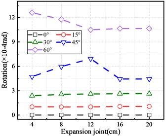
b) Rotation of main beam
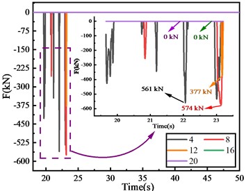
c) Pounding force between main beam and abutment
However, when the lower expansion joint is closed under the earthquake action, the collision will change the plane rotation effect of the main beam, resulting in the enhanced rotation effect of the main beam in the direction of off acute angle and increased damage of the shear key at the acute angle. In addition, the larger the skew angle is, the smaller the expansion joint size will be corresponding to zero collision state between the main beam and the abutment.
4.2. Influence of shear key gap on seismic response of Skew bridge
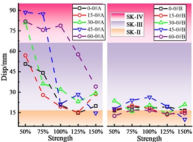
Fig. 7 shows the damage status of the key components of the skew bridge under different shear key gaps. All the bearings in this figure have minor damages (B-Ⅱ), and the bearing displacement increases linearly with the increasing shear key gap because the restraining effect of the shear key on the main beam is weakened. When the skew angle is within the range of 30° to 60°, the pier displacement ductility factor decreases with the increase of the shear key gap because the force transmitted to the pier decreases through the shear key. The plane rotation of the main beam is minimal, and the gap between the shear key has little bearing on the longitudinal response of the main beam when the skew angle is less than 30°. Since the pier top displacement is primarily longitudinal, the pier displacement ductility factor essentially stays to be stable.
The influence of shear key gap on the bearing displacement and the shear key deformation is completely different. In general, the shear key deformation at the side with the acute angle reduces as the gap widens. However, when the gap is between 4-6 cm, the shear key deformation slightly increases, while the shear key deformation at the side with the obtuse angle initially decreases and then grows. Other researchers also found that an appropriate shea key gap can reduced the collision response, but also an excessive gap would lead to a significant increase in the main beam displacement [15].
Fig. 7Damage of skew bridge key components with different shear key strengths
a) Bearing damage
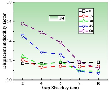
b) Pier damage
c) Shear key damage of abutment 0#
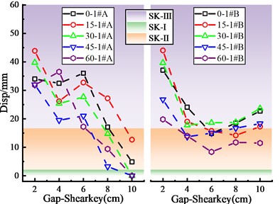
d) Shear key damage of pier 1#
4.3. Influence of shear key strength on seismic response of Skew bridge
Fig. 8(a)-(d) displays the damage state of significant skew bridge components at various shear key strengths. According to the damage analysis results, the shear key strength has a greater influence on bearing, pier, and shear key damage states than the expansion joint or shear key gap.
Fig. 8Damage of key components of skew bridge with different shear key strengths
a) Bearing damage
b) Pier damage
c) Shear key damage of abutment 0#
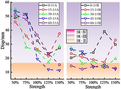
d) Shear key damage of pier 1#
When PGA is 0.3 g, the bearing has a minor damage (B-Ⅱ), and the bearing displacement at the abutment is greater than that at the pier. When the skew angle is between 0° and 30°, the bearing displacement drops initially and then increases as the shear key strength increases, reaching its maximum at the 125 % shear key strength. When the skew angle exceeds 30°, the bearing displacement generally shows a decreasing trend. The pier is in an elastic condition at different skew angles, and the pier ductility factor grows as the shear key strength increases. More crucially, the bigger the skew angle is, the greater the influence of shear key strength is on pier ductility factor.
Due to that the skew bridge tends to turn to the acute angle side, the damage of the shear key at the acute angle is relatively large and reaches the state of the severe damage (SK-Ⅳ), but the shear key at the obtuse angle does not damage so much and has mainly moderate damage (SK-Ⅲ). Moreover, the deformation of the shear key at the acute angle of the main beam is consistent with the change rule of the bearing displacement. The analysis results show that although increasing shear key strength can reduce the upper structure seismic response, it increases the damage of the lower structure, which is consistent with the points of other researchers [4, 31].
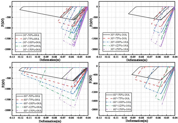
From the damage results of the key components of the skew bridge, the shear key deformation is highly related to the bearing deformation, which also shows that the shear key, as a limiting component, can greatly affect the overall seismic performance of the structure. The force-displacement curve of the shear key is used to demonstrate the influence mechanism of shear key strength on skew bridge damage, as illustrated in Fig. 9(a-c). The internal force of shear key on the acute angle side grows with increasing strength, and the deformation progressively reduces. Nevertheless, when the shear key strength exceeds 125 %, the internal force of the shear key increases, as does the deformation of the shear key. When the collision force between the shear key and the main beam grows, the force transmitted to the substructure that increases the risk of substructure damage. Therefore, when setting the shear key in a strong earthquake area, the shear key should be considered as a fuse element that is permitted to reach the serious damage state, thus protecting the substructure damages which are difficult to repair and expensive.
Fig. 9Influence of shear key strength on shear key deformation
4.4. Reasonable parameters under different skew angles
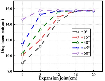
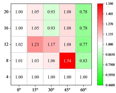
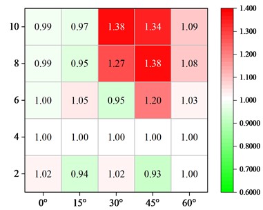
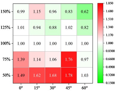
In the three components of the bearing, shear key and pier, the pier is as a capacity protection component under the earthquake action which is required to avoid the damage as much as possible. The shear key is an important and replaceable component that restricts the main beam from generating excessive displacement. As for the laminated rubber bearing, it is prone to subsidence problems due to excessive displacement of the main beam under the action of ground motion. With reference to the damage characteristics of the components under different parameters of the skew bridge, the displacement of the main beam should be limited to prevent subsidence and avoid pier damage. In this study, the main beam displacement influence coefficient under the original design parameters of the typical skew bridge is set to 1.0, which is then calculated by the Eq. (3):
where, is the main beam displacement influence coefficient; is the value of seismic response under the original design parameters of the typical skew bridge; is the value of seismic response under other design parameters in Table 1.
Fig. 10Effect of different parameters on main beam displacement
a) Abutment joint
b) Shear key gap
c) Shear key strength
Fig. 10 shows the influence of the abutment expansion joint, shear key strength, and shear key gap on the main beam displacement under various skew angles. For straight bridges, the expansion joint and shear key gap have a minimal impact on the damage of bearing and pier, and the influence coefficient of main beam displacement is basically unchanged. The main beam displacement factor increases initially and subsequently drops with increase of the expansion joint in skew bridges. Moreover, the bigger the skew angle is, the smaller the expansion joint is corresponding to the peak displacement of the main beam. In order to make full use of the effect of the shear key to limit the displacement of the main beam, smaller shear key gap can be used. Compared with the expansion joint and the shear key gap, the shear key strength is changed as the most effective measure to reduce the seismic response of the main beam. The displacement parameter increases first and then decreases slightly with the increasing strength, but the pier damage increases. Therefore, it is not recommended to use a high-strength shear key in the areas with high seismic intensity. It is recommended to increase the overlapping length of the bridge pier and abutment to avoid the beam falling. Based on the above analysis, the parameters of continuous beam bridge at each skew angle are recommended in Table 8.
Table 8Parameter recommendations under different skew angles
Skew angle | Gap (m) | Shear key gap (m) | Shear key strength |
0° | 0.04 | 0.02 | 100 % |
15° | 0.04 | 0.02 | 125 % |
30° | 0.16 | 0.02 | 125 % |
45° | 0.12 | 0.02 | 150 % |
60° | 0.12 | 0.02 | 150 % |
5. Conclusions
In this research, a typical three-span skew continuous beam bridge is subjected to a three-dimensional finite element analysis in the OpenSees platform. The paper compares the influence of the expansion joint (4-20 cm), the shear key gap (2-10 cm) and the shear key strength (50%-150 %) on the seismic response at different skew angles (0-60°). The damage conditions of bearing, shear key and piers are evaluated according to the preset damage criteria. Finally, according to the influence of relevant parameters on the damage of the key components, reasonable parameter setting suggestions under different skew angles are obtained. The main conclusions of this paper are as follows:
1) Under the action of earthquake ground motion with 0.3 g PGA, the seismic force transmitted to the pier is small, and the pier is elastic owing to the sliding of the bearing, but the damage degree of the shear key is larger than that of the bearing and pier. As the collision between the main beam and the abutment causes the main beam to rotate in the direction of the acute angle, the damage of the shear key at the acute angle is greater than that at the obtuse angle, so the shear key at the acute angle needs to be strengthened.
2) When the expansion joint is so large that there is no collision between the main beam and the abutment, so the expansion joint cannot induce the damage of the key components. When the main beam collides with the abutment, the collision will increase the plane rotation effect of the main beam. With an increase in the expansion joint, the damage to the bearing and shear key initially rises and subsequently falls. The expansion joint that corresponds to the maximum displacement of the bearing and shear key is smaller in case of a bigger skew angle.
3) Although the shear key increase can greatly reduce the damage to the shear key and the pier, the main beam deformation limiting effect is significantly diminished, leading to a linear growth of bearing slip and an increased danger of the main beam subsidence. So, it is not recommended to increase the shear key gap.
4) The shear key is an important component to limit the excessive displacement of the main beam. The increase of shear key strength initially reduces the damage rate for the bearing and shear key, but then it is increased slightly. However, the pier damage becomes obviously larger, if the skew angle increases, and the damage parameters of the bearing, shear key and pier become more significant. In the strong vibration area, it is recommended to take the shear key as a “fuse element” and increase the overlapping length of abutment and pier for mitigating the risk of beam falling.
5) According to the analysis of the influence of expansion joint, shear key gap and shear key strength on the damage of key components of skew bridge, the suitable seismic performance parameters under different skew angles of typical three-span continuous beams are obtained. For any oblique angle, the shear key gap can be reduced to 2 cm, and the shear key strength can be increased to 125 % or 150 %. When the skew angle is between 30° and 60°, the expansion joint size can be increased to 12 cm or 16 cm.
References
-
A. Abdel-Mohti and G. Pekcan, “Seismic response of skewed RC box-girder bridges,” Earthquake Engineering and Engineering Vibration, Vol. 7, No. 4, pp. 415–426, Dec. 2008, https://doi.org/10.1007/s11803-008-1007-4
-
C. Galasso, P. Kaviani, A. Tsioulou, and F. Zareian, “Validation of ground motion simulations for historical events using skewed bridges,” Journal of Earthquake Engineering, Vol. 24, No. 10, pp. 1652–1674, Oct. 2020, https://doi.org/10.1080/13632469.2018.1483277
-
L. S. Chen, W. L. Zhuang, and H. Q. Zhao, Report on Highway’ Damage in the Wenchuan Earthquake: Bridge. (in Chinese), Beijing: China Communication Press, 2012.
-
S. Aldea, R. Bazaez, R. Astroza, and F. Hernandez, “Seismic fragility assessment of Chilean skewed highway bridges,” Engineering Structures, Vol. 249, p. 113300, Dec. 2021, https://doi.org/10.1016/j.engstruct.2021.113300
-
M. Q. Lu, Q. S. Yang, and Y. Y. Li, “Torsion effects of skew angles on skew bridges during earthquakes,” (in Chinese), Journal of Harbin Engineering University, Vol. 33, No. 2, pp. 155–159, 2012.
-
Q. Zhao, S. Dong, and Q. Wang, “Seismic response of skewed integral abutment bridges under near-fault ground motions, including soil-structure interaction,” Applied Sciences, Vol. 11, No. 7, p. 3217, Apr. 2021, https://doi.org/10.3390/app11073217
-
P. Apirakvorapinit, J. Mohammadi, and J. Shen, “Analytical investigation of potential seismic damage to a skewed bridge,” Practice Periodical on Structural Design and Construction, Vol. 17, No. 1, pp. 5–12, Feb. 2012, https://doi.org/10.1061/(asce)sc.1943-5576.0000094
-
A. Abdel-Mohti and G. Pekcan, “Effect of skew angle on seismic vulnerability of RC box-girder highway bridges,” International Journal of Structural Stability and Dynamics, Vol. 13, No. 6, p. 1350013, Aug. 2013, https://doi.org/10.1142/s0219455413500132
-
J. W. Wang, T. Y. Wu, S. H. Li, and J. Z. Li, “Refined study on longitudinal seismic impact response of skew simply supported beam bridges,” (in Chinese), Vibration and shock, Vol. 35, No. 8, pp. 194–200, 2016.
-
Z. Yang, C. Kun, and N. Chouw, “Experimental evaluation of the seismic response of skewed bridges with emphasis on poundings between girder and abutments,” Shock and Vibration, Vol. 2019, No. 15, pp. 1–15, Dec. 2019, https://doi.org/10.1155/2019/4069817
-
X. Liu, W. Guo, J. Li, and H. Zhang, “Seismic study of skew bridge supported on laminated-rubber bearings,” Advances in Civil Engineering, Vol. 2020, No. 17, pp. 1–17, Nov. 2020, https://doi.org/10.1155/2020/8899693
-
S. Wu, I. G. Buckle, A. M. Itani, and D. Istrati, “Experimental studies on seismic response of skew bridges with seat-type abutments. II: results,” Journal of Bridge Engineering, Vol. 24, No. 10, p. 04019097, Oct. 2019, https://doi.org/10.1061/(asce)be.1943-5592.0001469
-
C. Kun, L. Jiang, and N. Chouw, “Influence of pounding and skew angle on seismic response of bridges,” Engineering Structures, Vol. 148, pp. 890–906, Oct. 2017, https://doi.org/10.1016/j.engstruct.2017.07.024
-
S. N. Somala, K. S. K. Karthik Reddy, and S. Mangalathu, “The effect of rupture directivity, distance and skew angle on the collapse fragilities of bridges,” Bulletin of Earthquake Engineering, Vol. 19, No. 14, pp. 5843–5869, Nov. 2021, https://doi.org/10.1007/s10518-021-01208-8
-
Q. Han, J.-Y. Chen, X.-L. Du, and C. Huang, “Nonlinear seismic response of skewed highway bridges subjected to bidirectional near-fault ground motions,” Journal of Bridge Engineering, Vol. 22, No. 7, p. 04017032, Jul. 2017, https://doi.org/10.1061/(asce)be.1943-5592.0001052
-
P. Zhang, W. Yuan, Z. Wang, and H. Qu, “Cost-based optimum design of the earthquake-resistant system for continuous skew overpasses,” Structures, Vol. 45, pp. 2051–2066, Nov. 2022, https://doi.org/10.1016/j.istruc.2022.10.038
-
F. Soleimani, B. Vidakovic, R. Desroches, and J. Padgett, “Identification of the significant uncertain parameters in the seismic response of irregular bridges,” Engineering Structures, Vol. 141, pp. 356–372, Jun. 2017, https://doi.org/10.1016/j.engstruct.2017.03.017
-
H. R. Noori, M. M. Memarpour, M. Yakhchalian, and S. Soltanieh, “Effects of ground motion directionality on seismic behavior of skewed bridges considering SSI,” Soil Dynamics and Earthquake Engineering, Vol. 127, p. 105820, Dec. 2019, https://doi.org/10.1016/j.soildyn.2019.105820
-
A. Khorraminejad, P. Sedaghati, and G. Foliente, “Response modification factor and seismic fragility assessment of skewed multi-span continuous concrete girder bridges,” Earthquakes and Structures, Vol. 20, No. 4, pp. 389–403, Apr. 2021, https://doi.org/10.12989/eas.2021.20.4.389
-
S. Wu, J. Huang, W. Li, C. Jiao, and J. Li, “Unseating of single-span bridges with skew angles out of the limit range for free rotation,” Structures, Vol. 32, pp. 1320–1330, Aug. 2021, https://doi.org/10.1016/j.istruc.2021.03.088
-
S. Wu and I. G. Buckle, “Effect of skew on the minimum support length requirements of single-span bridges with seat-type abutments,” Earthquake Spectra, Vol. 36, No. 3, pp. 1119–1140, Aug. 2020, https://doi.org/10.1177/8755293020919427
-
Y. Huang and Y. Xu, “Analysis of rational finite element model of two-span skew girder bridge based on shaking table test,” Advances in Civil Engineering, Vol. 2022, pp. 1–17, Jun. 2022, https://doi.org/10.1155/2022/9446398
-
S. Mangalathu, G. Heo, and J.-S. Jeon, “Artificial neural network based multi-dimensional fragility development of skewed concrete bridge classes,” Engineering Structures, Vol. 162, pp. 166–176, May 2018, https://doi.org/10.1016/j.engstruct.2018.01.053
-
“JT/T4-2019, Detailed rules for seismic design of highway bridges,” (in Chinese), People’s Communications Press, Beijing, 2019.
-
F. Mckenna, G. L. Fenves, and M. H. Scott, “Open system for earthquake engineering simulation,” University of California Berkeley, California, 2000.
-
“JTG/T 2231-01-2020, Code for seismic design of highway bridges,” (in Chinese), People's Communications Press, Beijing, 2020.
-
P. F. Silva, S. Megally, and F. Seible, “Seismic performance of sacrificial exterior shear keys in bridge abutments,” Earthquake Spectra, Vol. 25, No. 3, pp. 643–664, Aug. 2009, https://doi.org/10.1193/1.3155405
-
Xu L., E.-Qin, and Li Jian-Zhong, “Design and experimental investigation of a new type sliding retainer and its efficacy in seismic fortification,” (in Chinese), Engineering Mechanics, Vol. 33, No. 2, pp. 111–118,199, Feb. 2016, https://doi.org/10.6052/j.issn.1000-4750.2014.06.0547
-
H. Tang, J. Z. Li, and C. Y. Shao, “Transverse performance of small and medium span girder bridges with plate type elastomeric pad bearings in the transverse direction,” (in Chinese), Journal of China Highway and Transport, Vol. 29, No. 3, pp. 55–65, 2016.
-
H. Hwang, J. B. Jernigan, and Y.-W. Lin, “Evaluation of seismic damage to Memphis bridges and highway systems,” Journal of Bridge Engineering, Vol. 5, No. 4, pp. 322–330, Nov. 2000, https://doi.org/10.1061/(asce)1084-0702(2000)5:4(322)
-
H. Du, L. Q. Qin, H. R. Deng, X. Xia, and R. H. Sun, “Seismic displacement response features and unseating analysis of simply-supported skewed bridges,” (in Chinese), Journal of Natural Disasters, Vol. 30, No. 3, pp. 101–111, 2021.
About this article

The support of the Transportation Construction Science and Technology Project of Department of and Transportation of Shanxi Province (2020-2-01) and the Transportation Construction Science and Technology Project of the Transportation Department of Inner Mongolia Autonomous Region (NJ-2020-17) are much appreciated.
The datasets generated during and/or analyzed during the current study are available from the corresponding author on reasonable request.
The authors declare that they have no conflict of interest.
