Abstract
To clear the wear effect of friction pendulum bearings (FPBs) on the seismic performance of multiple long-span continuous girder bridges, the rapid sliding performance test of the FPBs was carried out to get the wear degree of the modified poly tetra fluoroethylene (PTFE) wear plates. Taking a 6×110 m long-span continuous girder bridge as the engineering background, the seismic response of the bridge with different wear degrees of the FPBs was analyzed. The results show that the modified PTFE wear plate of the FPBs was severely worn in the rapid sliding performance test, and the friction coefficient was first increased to 0.09 and then decreased to 0.016. When the maximum displacement was reached, the bearing collided with the limitation block. Moreover, the internal forces of the critical pier were increased, and the bottom of the piers entered plasticity due to the wear of the FPBs. Due to the change in the seismic performance of the bridge, it is suggested that the rapid sliding performance of FPBs should be tested to ensure the structure safety of the long-span continuous girder bridge in rare earthquakes.
Highlights
- Fast sliding test of the friction pendulum bearings (FPBs)
- Friction coefficient of the modified PTFE wear plate
- Effect of wear of FPBs on the seismic performance of the bridge
1. Introduction
At present, bridges construction has entered a stage of rapid development. Many long-span bridges with complex construction conditions, high technology, and novel structures have been built [1]. However, the earthquake is a particularly prominent disaster to multiple long-span continuous girder bridges. The seismic design should be carried out to prevent earthquakes [2]. Commonly, seismic design methods include ductile design and seismic isolation design [3]. In the ductile design, the seismic performance of bridges is improved by setting plastic hinges in the piers. However, the damage to the piers requires a large amount of repair work after the earthquake. In the seismic isolation design, some equipment, such as isolation bearings and energy dissipation devices, are installed between the main girders and piers of the bridge to dissipate and isolate the seismic energy [4].
Usually, there are two types of seismic isolation bearings on large-span continuous girder bridges. One is rubber isolation bearing such as lead rubber bearings. The other is the FPBs. However, the rubber isolation bearings have some flaws, such as low bearing capacity, rubber aging, and lead pollution, which limit the application of the bearings. FPBs made of steel have the advantages of high vertical bearing capacity, self-resetting and stable performance. Due to FPBs, the structural nature period is prolonged and the dynamic amplification effect is weakened [5], [6]. The core component of FPBs is a friction pair composed of a stainless steel mirror plate and a wear-resistant plate. While the bearing strength, wear resistance, and high temperature stability of the wear-resistant plate are weaker than the stainless steel mirror plate [7]. Based on a large number of experiments, it is found that the wear-resistant plate made of PTFE has a low sliding friction coefficient [8], [9]. The dynamic friction coefficient of FPBs increases with the sliding speed and the vertical load [10], [11]. Under rapid sliding, the vertical load significantly affects the friction coefficient [12], [13].
Lots of research were conducted on the parameters and isolation performance of FPBs [14]. Hamaguchi et al. [15] found that due to the serious wear, the friction coefficient of FPBs increased about three times, which greatly affects the durability of the bearing. The usable thickness of the PTFE plate is required to be larger than 50 % in AASHTO specification. Once the wear rate exceeds 50 %, the bearing capacity and isolation performance of FPBs will be reduced[16]. Almazán et al. [17] analyzed the influence of FPBs on the structural response after the sliding block was detached under high-intensity earthquakes and found that although the torsion amount was small, the interlayer variation was large to 50 % in severe cases. Jangid et al. [18], [19] investigated the seismic isolation performance of FPBs under near-field earthquakes and found that the isolation effect could be exerted when the friction coefficient is 0.05-0.15.
Currently, the research is mainly focused on the design parameters and friction coefficient of FPBs. However, the wear properties of the conventional wear-resistant plate, such as the PTFE plates and modified PTFE plates under fast friction in earthquakes, and the impact of the worn plates on the seismic performance of long-span continuous girder bridges were few studied. Since connecting the girders and the piers, the isolation bearings are vital components in bridges. Under long-term complex horizontal loads such as vehicles and wind, the performance of the isolation bearings is deteriorated or fails which seriously reduces the seismic isolation effect and threats bridge safety. Therefore, the investigation of the effect of FPBs wear on the seismic performance of the isolated bridges is significant for the safety evaluation of the bridges during their service life and the inspection and maintenance.
In this paper, the wear process of the modified PTFE wear plate in rare earthquakes was carried out by the rapid friction performance test of the FPBs to determine the wear degree. Then the influence of the wear-resistant plate of FPB on the seismic response of the bridge was studied by a nonlinear time history method based on a long-span continuous girder bridge. The results provide the basis for the seismic evaluation and inspection of bridges with FPBs.
2. Rapid friction performance test of FPBs
2.1. Specimen design
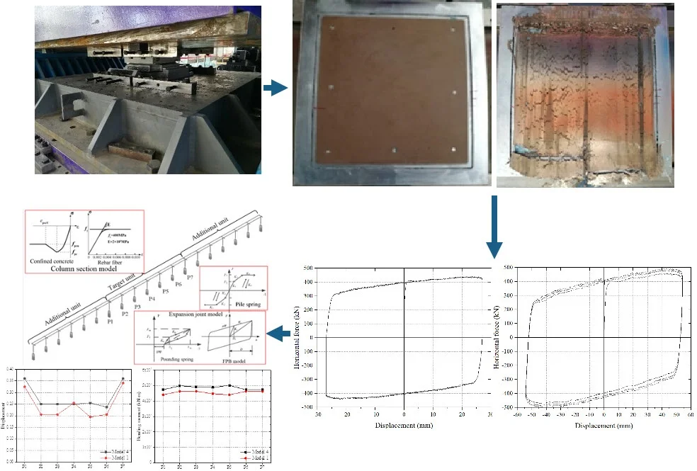
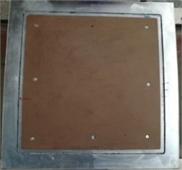
The specimens are selected from the conventional bearings in a long span continuous girder bridge. The design capacity of the bearing is 10 MN and the initial sliding force is 1000 kN. The top and bottom seat plates of the specimen are 1110 mm×500 mm and 1380 mm×500 mm, respectively. The curvature radius is 3.8 m. The seat plates were made of hot-rolled Q345 steel and the wear-resistant plates were made of modified PTFE. The specimen of FPBs is shown in Fig. 1. The images were taken by the authors when they done experiments in Test Centre of CCCC Highway Bridges National Engineering Research Centre, and the copyright is reserved by the author. And they have not been used in other papers.
2.2. Test design
The test was carried out in the Test Centre of CCCC Highway Bridges National Engineering Research Centre. The rapid friction performance of FPBs was tested on the dynamic testing machine, which was equipped with actuators in three directions. The maximum horizontal load is 3000 kN and the vertical static force is 30000 kN. The horizontal peak speed of loading is 700 mm/s. The test loading of the specimens is shown in Fig. 2.
In the test, the vertical design load of 10000 kN was applied to the specimens first. Then the horizontal cyclic load was applied to the specimens with the fundamental frequency of 0.256 Hz. There were three cases whose loading amplitudes were 25 %, 50 %, and 75 % of the seismic design displacement of 108 mm of the bearings. The specific loading parameters are shown in Table 1.
Fig. 1Specimen of FPBs
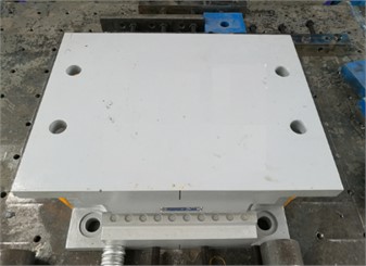
a) Specimen photo
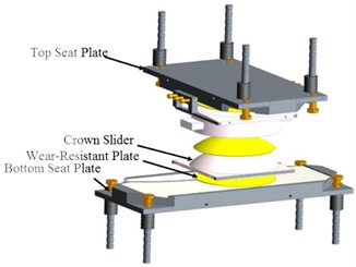
b) Specimen construction
Fig. 2Rapid friction performance test of FPBs
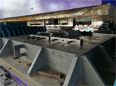
Table 1Loading conditions of the rapid friction performance test of the bearing
Specimen No. | Vertical load (kN) | Amplitude (mm) | Frequency (Hz) | Peak speed (mm/s) | Cycles |
Case 1 | 10000 | 27 | 0.256 | 43.4 | 3 |
Case 2 | 10000 | 54 | 0.256 | 86.9 | 3 |
Case 3 | 10000 | 81 | 0.256 | 130.3 | 3 |
2.3. Wear condition of the specimens
The wear degree of the wear-resistant plate of the FPBs is shown in Fig. 3. Before loading, the surface of the wear-resistant plate was intact. However, after the test of Case 3, it could be found that there was some wear debris left on the wear-resistant plate and the edge of the plate along the sliding direction of the bearing had been broken. The reason for the serious damage to the wear-resistant plate was that lots of heat were generated during the rapid friction between the wear-resistant plate and the stainless steel mirror plate. The thermal stability of the wear-resistant plate was weaker than that of the stainless steel mirror plate. When the critical resistance was reached, the creep resistance and wear resistance of the wear-resistant plates decreased rapidly. At the same time, the sliding block of FPBs swung along the sliding direction, resulting in a more significant compressive stress on the edge of the wear-resistant plate and up to being torn [20], [21].
2.4. Test results
The horizontal load-displacement hysteresis curves of Case 1 and Case 2 are shown in Fig. 4. It can be found that when the loading speed is less than 100 mm/s, the curves are full and smooth which are consistent with the theoretical hysteresis curve of the FPB. The friction coefficients of Case 1 and Case 2 is 0.039 and 0.041, which deviate from the design value of 0.04 are –0.4 % and 2.7 %, respectively. Moreover, the plastic stiffness of Case1 and Case2 are 2.44 kN/mm and 2.54 kN/mm. In low loading speed, the specimens show a good energy consumption performance.
Fig. 3Surface of the wear-resistant plate
a) Before the test
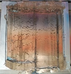
b) After the test
Fig. 4Hysteresis curve of force and displacement in Case 1 and Case 2
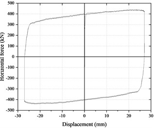
a) Case 1
b) Case 2
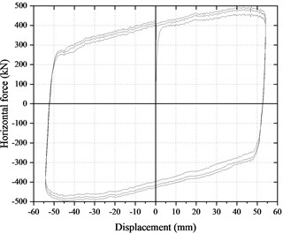
Fig. 5Hysteresis curve of force and displacement in Case 3
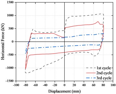
The horizontal force-displacement hysteresis curve of Case 3 is shown in Fig. 5. When the loading speed was increased to 130.3 mm/s, the initial horizontal force of the friction sliding of the bearing in the first cycle reached 904 kN while it was less than 400 kN in Case 1 and Case 2 which indicated that the surface of the wear resistant plate was damaged. In the second cycle, the horizontal force remained in the range of 530-650 kN, which indicated that the wear resistant plate surface continues to be worn. After that, the exposed new surface of the wear plate was under the action of self-lubrication which reduced the friction coefficient gradually. In the third cycle, the horizontal force was reduced to 156 kN, which indicated that the 3mm wear resistant plate of the FPBs had been worn out, and the friction between the stainless steel mirror surface and the rotating spherical crown occurred. Therefore, it can be found that the surface of the modified PTFE wear-resistant plate was worn during rapid sliding friction. The friction coefficient of the bearing first increased to 0.09 and then gradually reduced to 0.05. At last, the friction coefficient was kept about 0.016.
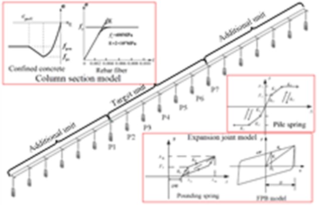
3. Finite element model and isolation parameters
3.1. Project overview
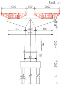
The total length of the long-span continuous girder bridge is 660 m long including six spans. The main girder made of C55 concrete is a boat-shaped box steel section with a width of 20 m and a height of 4 m. The top width of the pier made of C40 concrete is 10 m in transverse and the bottom width is changed with the height. The hexagonal variable section is used in the piers. The pile foundation made of C35 concrete is adopted with a diameter of 2.5 m. The bridge layout is shown in Fig. 6.
Fig. 6Layout of the bridge
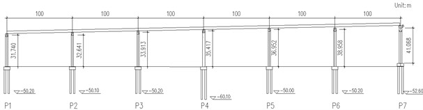
The top of each pier adopted double FPBs. A fixed bearing and a lateral sliding FPB were set on the top of Pier P5. Two direction sliding bearings were put on the other piers and the allowable displacement of the bearings was 150 mm. The seismic fortification of the bridge was VIII degrees and the design seismic peak acceleration was 0.2 g [22].
3.2. Finite element model
The three-dimensional finite element model of the bridge was established by SAP2000 for seismic performance analysis. The total number of elements is 5591 and the nodes are 5865. The longitudinal direction of the bridge was taken as the axis and the vertical direction as the axis in the model. The main girder, piers and piles were all simulated by beam elements. The element length of the main beam is 2 meters. The length of the plastic hinge area of the pier is 1 meter, and the others are 3 meters. Each girder end is supported by two bearings. The spring element was used to model the characteristic of the interaction of soil and pile. The flow of the bridge modeling is shown in Fig. 7. Fig. 8 shows the finite element model of the bridge.
3.3. Model parameters of FPBs
When only considering the unidirectional horizontal earthquake, the expression of the horizontal restoring force of the FPBs is as follows:
where is the vertical force of the bearing which can only be compressed but not tensioned; is the radius of curvature of the sliding surface; is the horizontal displacement of the bearing; is the friction coefficient which usually adopts the Coulomb friction model or the speed-variable friction model; is a dimensionless quantity which satisfies the Bouc-Wen model [16].
Fig. 7Flow chart of the modeling
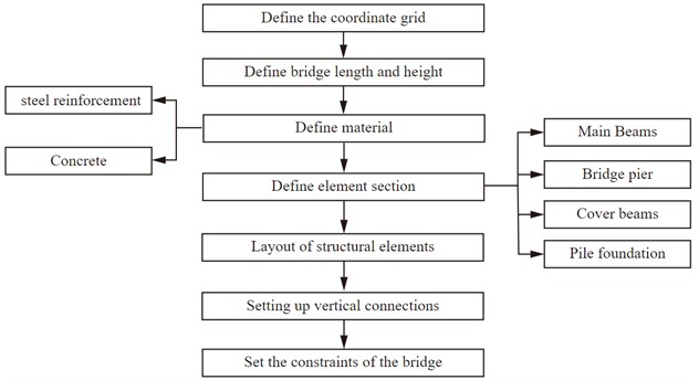
Fig. 8Finite element model of the bridge
a) Whole model
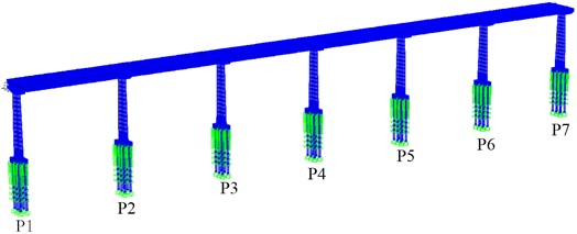
b) Target unit model
The natural period of FPBs is determined by the curvature radius of the sliding surface, as shown in Eq. (2):
Under unidirectional horizontal earthquakes, FPBs are equivalent to the nonlinear viscous element, as shown in Fig. 9.
Fig. 9Hysteresis model of FPBs
In the figure, is the initial yield displacement; is the initial stiffness; is the yielding stiffness:
When considering the seismic action in the horizontal direction, the expression of the horizontal restoring force of FPBs is as follows:
where and are the horizontal forces of the bearing along the and directions, respectively; and are the horizontal shear deformation of the bearing relative to the ground along the and directions, respectively; and are the hysteretic characteristic components considering the motion state of the bearing, the direction of the friction force and the bidirectional coupling effect, which are usually simulated by Park-Wen model [16].
According to the above test results, the damage procedure of the bearing is divided into three states, including normal sliding, worn sliding and steel friction. To investigate the effect of wear on the seismic response of the bridge, three constrained systems of FPB models were established according to the work states of the bearings. The behavior of the FPBs is simulated by the professional Multi-Linear Plastic (Wen) element [23], as shown in Fig. 9. The system parameters are shown in Table 2.
Table 2Parameters of FPBs restraint system
Model No. | FPBs work state | Radius of curvature / m | Friction coefficient |
Model 1 | normal sliding | 3.8 | 0.040 |
Model 2 | worn sliding | 3.8 | 0.090 |
Model 3 | steel friction sliding | 3.8 | 0.016 |
3.4. Earthquake waves
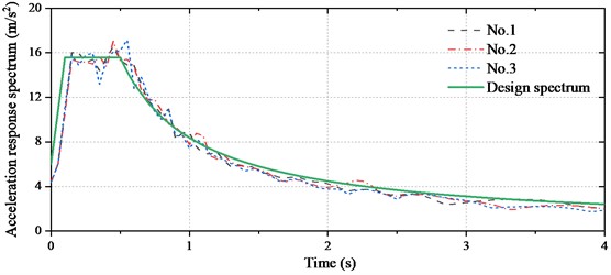
Based on the basic objectives of seismic fortification and the ground motion characteristics of the bridge site, the earthquake parameters were determined with the E2 exceedance probability [22]. The return period of E2 earthquake is 2500 years and the exceeding probability is 2 % every 50 years. The design acceleration response spectrum is shown in Eq. (6):
where, is the response spectrum period; is the starting point of the response spectrum platform; is the characteristic period of the response spectrum; is the relative response spectrum value corresponding to period ; is the maximum value of the relative response spectrum; is the attenuation coefficient; is the response spectrum value corresponding to period . The parameters of the design response spectrum are shown in Table 3.
Table 3Parameters of design response spectrum (Damping ratio = 5 %)
Exceedance probability | (s) | (s) | (m/s2) | |||
2 % every 50 years | 0.10 | 0.50 | 2.6 | 0.9 | 6.00 | 1.59 |
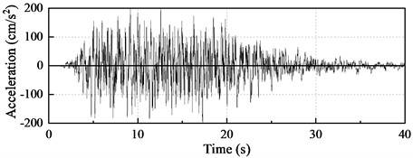
Fig. 10Earthquake waves
a) No. 1
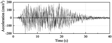
b) No. 2
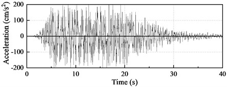
c) No. 3
For bridges with seismic isolation design, the energy is mainly dissipated by the isolation devices to effectively reduce the structural response so that the piers keep elastic [24], [25]. There are three earthquake waves in horizontal and vertical directions. The peak ground acceleration of the vertical wave is 0.65 times that of the horizontal waves. The results below are the average of the results in the three waves. The artificial earthquake waves are shown in Fig. 10 and the response spectrum is shown in Fig. 11.
Fig. 11Response spectrum curves
4. Influence of FPBs wear on the seismic isolation performance of bridges
4.1. Bearing displacement
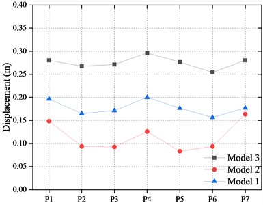
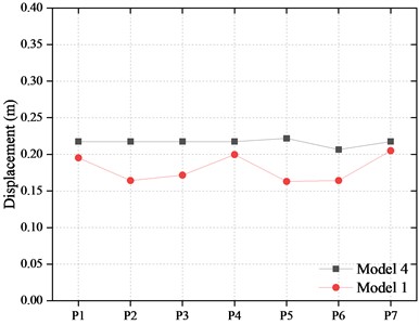
The average displacements of the bearings in the bridge are shown in Fig. 12. It can be found that the displacements of the bearing on the outermost piers are larger than those of the other piers. The reason is that the type and performance of FPBs on the outermost piers and others are different. There were four FPBs in parallel to support the girders on the outermost piers. While two bearings were used to support the girder at other piers. Therefore, the displacement of a single bearing on the outermost pier was larger than that of the other piers.
Fig. 12Displacement of FPBs
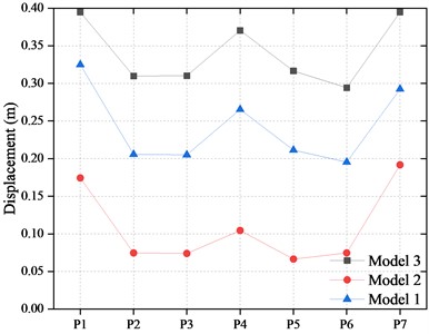
a) In longitudinal
b) In transverse
In Model 2, the wear-resistant plate of the FPBs was damaged, which led to a higher friction coefficient. The bearing played as a rigid constraint to the girders and decreased the displacement of the bearing. Compared with Model 1, the longitudinal displacement of the bearing on each pier was reduced by 58.7 % on average, and the lateral displacement was reduced by 37.63 % on average.
As the friction coefficient of the FPBs in Model 3 is the smallest, the bearing system is similar to the free constraint, which increases the longitudinal and lateral displacement of the bearing. The maximum longitudinal displacement of the outermost piers and other piers reached 0.395 m and 0.371 m, respectively, which exceeded the design displacement of the FPBs. The longitudinal and lateral displacements of the FPBs on each pier are increased by 40.73 % and 52.85 % on average to that of Model 1. These cause the bearing sliding to the limitation position and collide with the blocker.
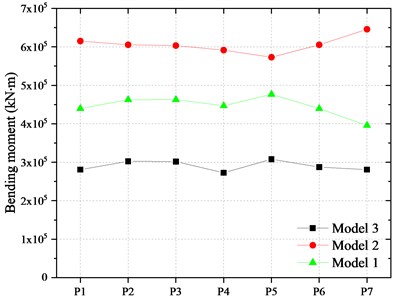
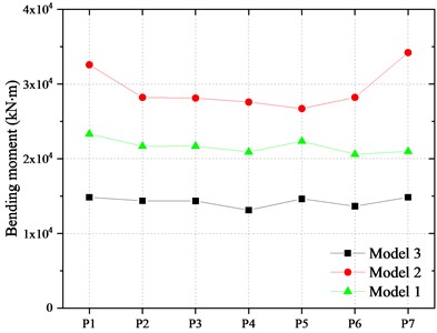
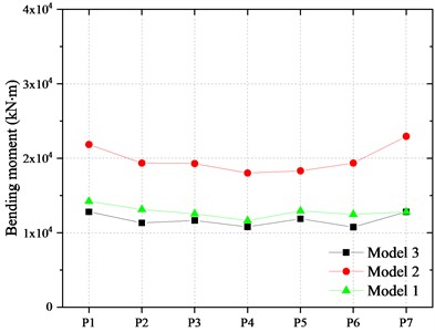
4.2. Bending moment at the bottom of piers
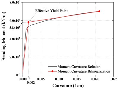
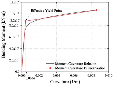
The bearing capacity analysis of piers was carried out. The fiber section of the piers is shown in Fig. 13. Each longitudinal steel bar was divided into one fiber. The moment-curvature relationship of the piers bottom section is shown in Fig. 14 and the effective yield moments of the piers are 5.8×10⁵ kN in longitudinal and 8.7×10⁵ kN in transverse, respectively.
Fig. 13Fiber section of piers
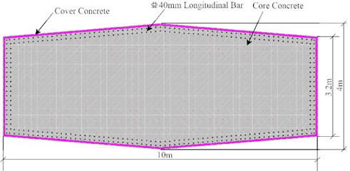
Fig. 14Moment-Curvature curves of piers
a) In longitudinal
b) In transverse
Fig. 15Bending moment at the bottom of the piers
a) In longitudinal
b) In transverse
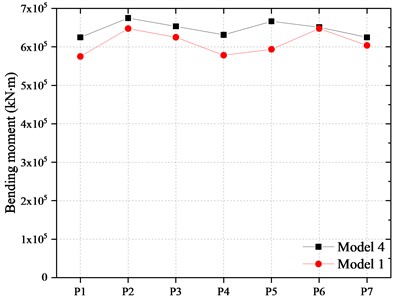
The bending moment at the bottom of piers is shown in Fig. 15. It can be found that the bending moment of the pier bottom in Model 2 is larger than that of Model 1 and the bottom section came into the plastic stage. On average, the longitudinal and the transverse bending moment of each pier bottom are 33.33 % and 54.75 % higher than that of Model 1. The main reason is that after the damage of the wear resistant plate in FPBs, the sliding displacement of the bearing decreases which leads to the increase of the inertial force of the main girder transmitted to the pier under earthquake. The bending moment of the pier in Model 3 is smaller than that of Model 1. The longitudinal and transverse bending moments of the pier are reduced by about 36.1 % and 11.05 % on average compared with Model 1.
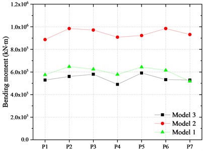
4.3. Internal force of pile foundation
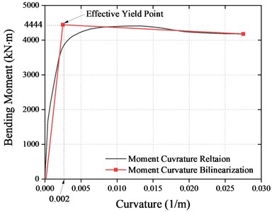
The bearing capacity analysis of the piles was carried out. The fiber section of the piles is shown in Fig. 16. Each longitudinal steel bar was divided into one fiber. The result of the pile section is shown in Fig. 17 and the effective yield moment of the pile is 4444 kN. Fig. 18 shows the bending moments at the top of the piles. It can be found that the variation law of the bending moment at the top of the piles in all models is similar to that of the piers. The longitudinal and transverse bending moments of the piles in Model 2 are increased by 32.85 % and 52.38 % compared to Model 1. Moreover, the longitudinal and transverse bending moments of piles in Model 3 are reduced by about 35.28 % and 9.55 % on average compared with Model 1. All the piles are still in the elastic stage.
Fig. 16Fiber section of piles
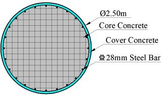
Fig. 17Moment-Curvature of piles
4.4. Influence of the limitation exceeding of the bearing displacement on the response of the bridge
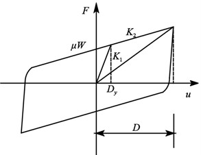
From the above analysis, it indicates that the worn of the wear resistant plate makes decrease the friction coefficient of FPBs, which causes a displacement of the bearing beyond the limitation. As a result, the collision between the blocker and FPBs occurred. To investigate the effect of rigid collision with the blocker and FPBs on the seismic dynamic response of the bridge, the cable restraint elements are set up in the longitudinal and lateral directions of the bearing to simulate the restraint effect of the blocker in the model of Model 4. The force vs. relative displacement hysteresis of the blocker is idealized as the Kinematic model, shown in Fig. 19. The gap width is assumed as 0.05 m and the is a constant value of 3.44×10⁶kN/m. The specific parameters of the model are shown in Table 4.
Fig. 18Bending moment on the top of the piles
a) In longitudinal
b) In transverse
Fig. 19Idealization of blockers
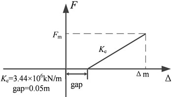
Table 4Parameters of the restraint systems to FPBs
Case No. | Radius of curvature (m) | Friction coefficient | of FPBs on outermost piers (mm) | of FPBs on other piers (mm) | ||
Longitudinal | Horizontal | Longitudinal | Horizontal | |||
Model 1 | 3.8 | 0.040 | / | / | / | / |
Model 4 | 3.8 | 0.016 | 360 | 220 | 260 | 220 |
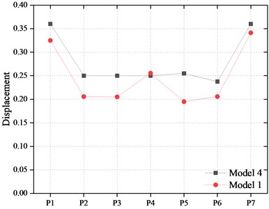
4.4.1. Displacement of FPBs
The displacements of FPBs considering the bearing limit are shown in Fig. 20. It can be found that when the blocker restricts the sliding, the maximum displacement of FPBs is limited to 0.220 m. That is, when the wear plate of the bearing is worn out, the displacement of the bearing increases. The sliding spherical crown of the bearing has obvious collision with the limit block, so as to limit the increase of the sliding displacement.
4.4.2. Bending moment of piers
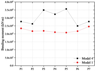
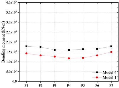
The bending moment of the pier and pile are shown in Fig. 21 and Fig. 22. Compared with Model 1, the longitudinal bending moment at the bottom of the piers in Model 4 increased by about 7.5 %-9.1 % and the transversal bending moment of the piers increased about 4.2 %-9.2 %. At the same time, the longitudinal and transverse bending moment at the top of the piles beneath the middle pier increases by 59.4 % and 36.0 %, respectively. The main reason is that the inertial force of the girder was transmitted to the piers of the bridge after FPBs reached the displacement limit and collided with the blocker.
Fig. 20Displacement of FPBs
a) In longitudinal
b) In transverse
Fig. 21Bending moment of the piers

a) In longitudinal
b) In transverse
Fig. 22Bending moment of the piles
a) In longitudinal
b) In transverse
5. Conclusions
1) In a rare earthquake, severe wear occurs on the modified PTFE wear resistant plate of the FPBs due to the rapid frictional sliding. The friction coefficient of the FPBs would first increase then decrease to 0.016 depending on the various wear degree.
2) After the friction coefficient of FPBs is reduced, the sliding displacement of the bearing will increase, which will cause a rigid collision between the bearing and the limit blocker, resulting in an increase in the seismic response of the substructure of the bridge. The maximum bending moment at the bottom of the pier increased by 9.2 %, and the bending moment at the top of the piles increased by 59.4 %.
3) It is suggested that the rapid sliding performance of FPBs should be tested to ensure the structural safety of the long-span continuous girder bridge in rare earthquakes.
References
-
G. Liu, Y. Gao, H. Wu, J. Ma, X. Zhang, and B. Fu, “Status and prospect of technical development for bridges in China,” (in Chinese), Chinese Science Bulletin, Vol. 61, No. 4-5, pp. 415–425, Feb. 2016, https://doi.org/10.1360/n972015-00912
-
X. S. Xia, L. B. Cui, and X. C. Chen., “Seismic isolation of long span and super long unit continuous beam bridge with friction pendulum bearings,” (in Chinese), Engineering Mechanics, Vol. 32, pp. 167–171, 2015, https://doi.org/10.6052/j.issn.1000-4750.2014.04.s029
-
J. Z. Li and Z. G. Guan, “Performance-based seismic design for bridges,” (in Chinese), Engineering mechanics, Vol. 28, No. S2, pp. 24–30, 2011, https://doi.org/10.2753/csh0009-4633350347
-
L. Wang et al., “Multi-dimensional seismic response analysis of long-span isolated continuous girder bridge with friction pendulum system,” (in Chinese), World Earthquake Engineering, Vol. 36, No. 2, pp. 129–137, 2020.
-
Y. L. Zhan, L. Zhang, and Q. Zhang., “Effects of parameters of friction pendulum bearings on seismic responses of seismically isolated bridge,” (in Chinese), Ridge Construction, Vol. 48, No. 3, pp. 45–49, 2018.
-
B. F. Wang, Q. Han, and X. L. Du, “Seismic response analysis of isolated bridge with friction pendulum bearings,” (in Chinese), China Civil Engineering Journal, Vol. 49, pp. 85–90, 2016.
-
P. Chen and Y. Zhou, “The applicable design method of isolated structure using friction pendulum system,” Earthquake Engineering and Engineering Vibration, Vol. 37, No. 1, pp. 56–63, Apr. 2007.
-
A. Mokha, M. Constantinou, and A. Reinhorn, “Teflon bearings in aseismic base isolation: Experimental studies and mathematical modeling,” NCEER-88-0038, National Center for earthquake engineering research, 1988.
-
A. E. Pigouni, M. G. Castellano, S. Infanti, and G. P. Colato, “Full-scale dynamic testing of pendulum isolators (Curved surface sliders),” Soil Dynamics and Earthquake Engineering, Vol. 130, p. 105983, Mar. 2020, https://doi.org/10.1016/j.soildyn.2019.105983
-
A. Mokha, M. C. Constantinou, and A. M. Reinhorn, “Further results on frictional properties of Teflon bearings,” Journal of Structural Engineering, Vol. 117, No. 2, pp. 622–626, Feb. 1991, https://doi.org/10.1061/(asce)0733-9445(1991)117:2(622)
-
C. Tsai, Bo-Jen Chen, W. Pong, and T. Chiang, “Interactive behavior of structures with multiple friction pendulum isolation system and unbounded foundations,” Advances in Structural Engineering, Vol. 7, No. 6, pp. 539–551, 2004.
-
P. Tsepelas and M. Constantinou, “NCEER-Taisei Corporation Research Program on Sliding Seismic Isolation Systems for Bridges: Experimental and analytical study of a system consisting of sliding bearings and fluid restoring force/damping devices,” PB94-219144, National Center for Earthquake Engineering Research, 1994.
-
M. Kumar, A. S. Whittaker, and M. C. Constantinou, “Characterizing friction in sliding isolation bearings,” Earthquake Engineering and Structural Dynamics, Vol. 44, No. 9, pp. 1409–1425, Jul. 2015, https://doi.org/10.1002/eqe.2524
-
Zhao Gui-Feng et al., “Effects of performance deterioration of friction pendulum bearings on seismic behavior of Hong Kong-Zhuhai-Macao isolated bridges in life-cycle period,” (in Chinese), China Journal of Highway and Transport, No. 12, pp. 10–16, 2016.
-
H. Hamaguchi and M. Higashino, “Development of low-friction factor sliding isolation device,” Proceedings of the 12th World Conference on Earthquake Engineering, pp. 156–169, 1999.
-
“Guide specifications for seismic isolation design,” Washington, American Association of State Highway and Transportation Officials, 2014.
-
J. L. Almazan and de La Llera J. C., “Accidental torsion due to overturning in nominally symmetric structures isolated with the FPS,” Earthquake Engineering and Structural Dynamics, Vol. 32, No. 6, pp. 919–948, 2003.
-
R. S. Jangid and J. M. Kelly, “Base isolation for near-fault motions,” Earthquake Engineering and Structural Dynamics, Vol. 30, No. 5, pp. 691–707, May 2001, https://doi.org/10.1002/eqe.31
-
R. S. Jangid, “Optimum friction pendulum system for near-fault motions,” Engineering Structures, Vol. 27, No. 3, pp. 349–359, Feb. 2005, https://doi.org/10.1016/j.engstruct.2004.09.013
-
S. P. Parida and P. Jena, “Selective layer-by-layer fillering and its effect on the dynamic response of laminated composite plates using higher-order theory,” Journal of Vibration and Control, 2022.
-
P. C. Jena, D. R. Parhi, and G. Pohit, “Dynamic investigation of FRP cracked beam using neural network technique,” Journal of Vibration Engineering and Technologies, Vol. 7, No. 6, pp. 647–661, Dec. 2019, https://doi.org/10.1007/s42417-019-00158-5
-
J. T. 2231-01-2020, “Specifications for seismic design of highway bridges,” (in Chinese), Beijing, China Communications Press, 2020.
-
M. Constantinou, A. Mokha, and A. Reinhorn, “Teflon bearings in base isolation II: modeling,” Journal of Structural Engineering, Vol. 116, No. 2, pp. 455–474, Feb. 1990, https://doi.org/10.1061/(asce)0733-9445(1990)116:2(455)
-
S. Pradhan, S. R. Das, P. C. Jena, and D. Dhupal, “Machining performance evaluation under recently developed sustainable HAJM process of zirconia ceramic using hot SiC abrasives: An experimental and simulation approach,” Proceedings of the Institution of Mechanical Engineers, Part C: Journal of Mechanical Engineering Science, Vol. 236, No. 2, pp. 1009–1035, Jan. 2022, https://doi.org/10.1177/09544062211010199
-
S. P. Parida, P. C. Jena, S. R. Das, D. Dhupal, and R. R. Dash, “Comparative Stress analysis of different suitable biomaterials for artificial hip joint and femur bone using finite element simulation,” Advances in Materials and Processing Technologies, Vol. 8, No. sup3, pp. 1741–1756, Oct. 2022, https://doi.org/10.1080/2374068x.2021.1949541
Cited by
About this article

This work was financially supported by CCCC Technology R&D Project (2019-ZJKJ-09), CCCC Academician Research Funding Project (YSZX-03-2021-02-B), National Key R&D Program of China (No. 2018YFB1600305), National Natural Science Foundation of China (Grant Nos. 51408009, 51608010).
The datasets generated during and/or analyzed during the current study are available from the corresponding author on reasonable request.
The authors declare that they have no conflict of interest.
