Abstract
Energy harvesting from rail vibration is a promising approach to solve the power supply problem in remote and off-grid areas. The major issue of current energy harvesting techniques and devices is the limited power generating capacity. In this paper, the authors put forward an elastic lever system to enhance the performance of an electromagnetic energy harvester. A vehicle-track coupling dynamics model is established to simulate the service condition of the energy harvester. The Power Amplification Factor (PAF), which is defined as the ratio between the output power with and without a lever system, is introduced to quantify the Enhanced Energy Harvester (EEH). It is found that the PAF can be greater than with a leverage ratio of . Simulation shows that the output power can be magnified by 430 times with an elastic lever system with a leverage ratio of 10. The amplification effect of the output power comes from two aspects, one is the magnifying effect of leverage itself and the other is the resonance effect. Additionally, it is found that a single EEH will increase the wheel-rail contact force slightly, which indicates the EEH is impractical for use as an approach for rail vibration reduction. Nevertheless, it will not have a significant negative effect on rail vibration.
Highlights
- Rail vibration
- Elastic lever system
- Enhanced energy harvester
1. Introduction
Rail transit is closely related to people’s lives. Numerous monitoring systems have been established to ensure the safety of passengers and goods on rails. However, the power supply problem in remote and off-grid areas has posed a big challenge for the railway community. The idea of using energy harvesting techniques as a potential power source has therefore become a hot topic in the past decade [1, 2]. Furthermore, with the development of Micro-electromechanical Systems (MEMS), the power consumption of sensors drops to an ultra-low level [3], which brings the idea of a self-powered monitoring system closer to reality [4, 5].
Train-induced rail vibration is considered to be the largest potential energy source. Nelson et al. [6] utilized both an inductive voice coil located near the rail and a piezoelectric device mounted under the rail for power harvesting for track monitors. Wang et al. [7] designed a mechanical power harvester with a rack pinion, flywheel, and rotational electromagnetic generator. Yuan et al. conducted a comprehensive investigation of piezoelectric drum transducers for energy generation on running urban vehicles [8]. The test results showed a root mean square (rms) output power of 0.081 mW under full urban load conditions in Shanghai. The peak open-circuit voltage could reach 50-70 V. Gao et al. [9] have developed energy harvesters based on magnetic suspension and piezoelectric configurations. The train-induce air flow was also taken as an important source of energy. Besides the electromagnetic and piezoelectric approaches, Dattaet et al. [10] reported a harvesting system designed across pavement structures to collect thermoelectric energy. In this study, the authors are aimed at powering the rail-side sensors in off-grid and remote areas, which are characterized by small scale dimensions MEMs (Micro Electromechanical Systems) sensors with lower power consumption (i.e. the typical power consumption is less than 100 mW [3]) so the large scale power generation equipment is not in the scope of this paper.
It is well-known that there is a linear amplification of displacement, velocity, and acceleration for a rigid lever with a leverage ratio greater than 1. Instead of using a rigid lever, this paper provides an elastic lever system to enhance the power generation capacity of the harvester based on the lever principle; it is referred to as an Enhanced Energy Harvester (EEH) hereafter. Two points are to be addressed in this paper: 1) the improvement of power generation capacity of the harvester with an elastic lever system; 2) the influence of the EEH on vehicle-track dynamics.
2. Theory and modeling
In this paper, we focus on the influence of a harvester with a lever on the vehicle-track dynamics and introduce the vehicle-track system coupling model.
2.1. Vehicle model
The vehicle subsystem is modeled as a multi-body system with 10 degrees of freedom (DOFs) moving on the track at a constant velocity [11]. From this model diagram, we can see the 10 DOFs are 1) vehicle vertical displacement, 2) vehicle pitch angle , 3) front bogie vertical displacement, 4) front bogie pitch angle, 5) rear bogie vertical displacement, 6) rear bogie pitch angle; 7) front bogie front wheelset vertical displacement, 7) front bogie rear wheelset vertical displacement, 9) rear bogie front wheelset vertical displacement, and 10) rear bogie rear wheelset vertical displacement.
Fig. 1Vehicle model with 10 degrees of freedom
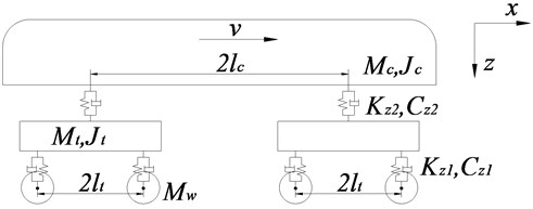
In Fig. 1, , and are the mass of the vehicle body, bogie and wheel set; and are the rotational inertia of the vehicle body and bogie; and are the stiffness of the primary and secondary suspension systems, and and are the damping of the primary and secondary suspension systems, respectively; is half of the distance between two axles of the same bogie; is half of the distance between two bogie centers; and v is the vehicle speed.
Therefore, it can be seen that the equation of vehicle motion is expressed as Eq. (1):
In Eq. (1), , and are the stiffness matrix, damping matrix and mass matrix of the vehicle, respectively; is the displacement vector of the vehicle, and is the load vector of the wheel-rail force.
2.2. Track model
The track model is based on a ballastless track substructure, which consists of four layers, i.e., the rail, sleeper, track slab and support layer. It is assumed to be an infinite Euler-Bernoulli beam supported on a discrete continuous elastic foundation, as presented in Fig. 2.
Fig. 2The dynamic model of track
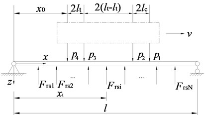
In the Fig. 2, is the vehicle speed; ( 1–) is the force of the rail pad, namely the rail-supporting force. is the total number of sleepers in the length ; The equation of motion of the track system is expressed in form of the fourth-order partial differential equation:
where , reaction force of rail pad, can be obtained as follows:
In Eq. (2) and Eq. (3), is the vertical vibration displacement of the rail; , are bending stiffness and linear density of the rail; and represent the stiffness and damping of railpad, respectively; are the coordinates of the contact points of the wheel and rail; is the Dirac delta function.
2.3. Vehicle-track vertical coupled system motion equation
Assuming that the vehicle and the track are connected through a linear Hertz contact spring [12], the wheel-rail force can be expressed as:
where is the displacement of the rail at the th wheel-rail contact point, is the track irregularity, and is the displacement of the th wheelset. The equation of motion of the vehicle-track coupled system can be expressed as Eq. (5):
where [] is the system mass matrix, [] is the system damping matrix, and the damping of the faster system contains the damping coefficient of rail pad and the equivalent damping coefficient for Ampere force, [] is the system stiffness matrix, [] is the conversion matrix, {} represents the generalized force column vector, {} stands for the generalized displacement column vector, and {} is the track irregularity column vector. The displacement column vector {} can be calculated by the Newmark- integration scheme.
2.4. Enhanced energy harvester system model
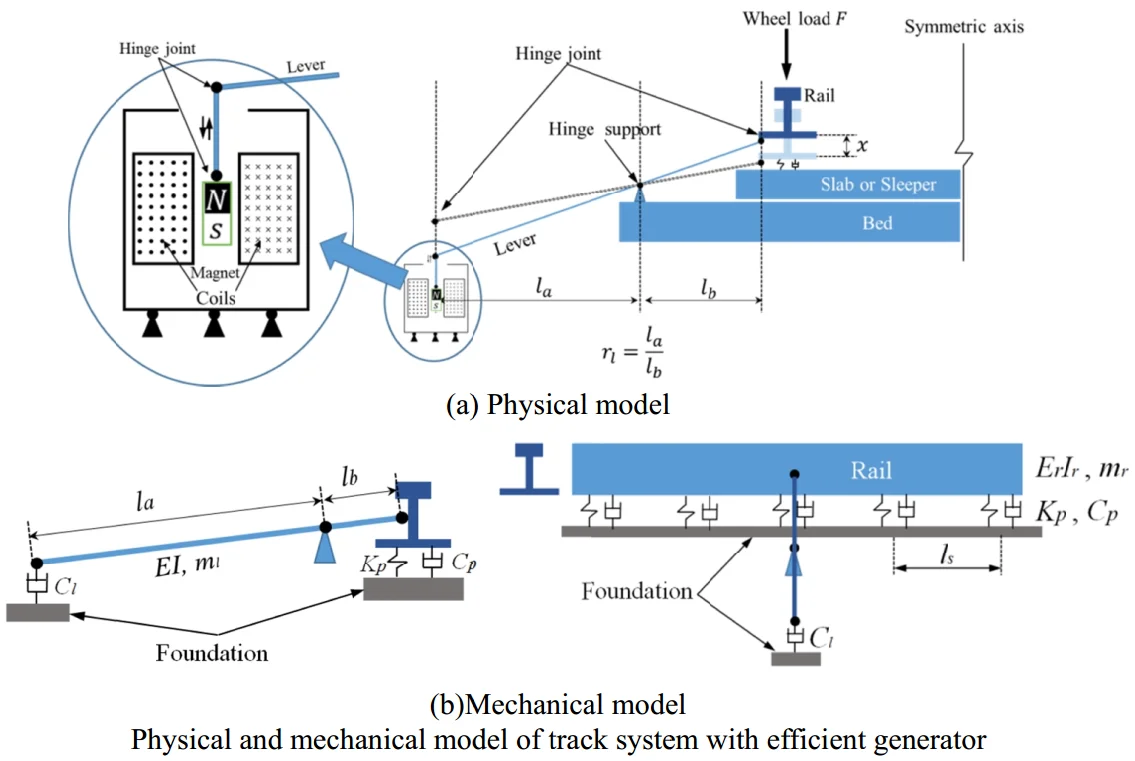
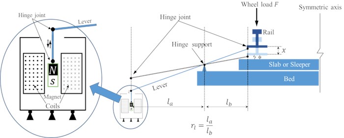
Fig. 3 shows a lateral view of the track section. A lever is mounted on the track slab via hinge supports, the near-end of which is connected to the rail and the far-end is fixed to an energy harvester. To simplify the model of the energy harvester, it is assumed that the magnetic field is uniform and that a piece of rigid wire is able to move along with the far-end of the lever. is the distance between the support hinge and the far-end point and is the distance of the nearend point to the support hinge, which indicates that the leverage ratio is .
Fig. 3Physical model of track system with enhanced energy harvester
Then, for an open circuit, the voltage output between the two ends of the wire can be obtained by Eq. (6):
where, is the magnetic field intensity and v is the moving speed of the far-end of the lever. The parameter is the number of turns of the coils. When a load resistance is added to the energy harvester, the circuit can be approximated as Fig. 4. is the inductance inside the energy harvester. According to Kirchhoff's voltage law, the relationship between , , and is given by Eq. (7):
Fig. 4The equivalent circuit of the electromagnetic energy harvester
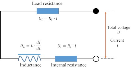
When the inductance is small, the voltage divided by inductance can be ignored. To simplify the model, the energy harvester is equivalent to a model of a closed wire cutting magnetic induction line and the magnetic field intensity is evenly distributed. Then we can obtain the current by Eq. (8):
where, is the equivalent length of the wire that cuts the magnetic induction line and . Eq. (8) indicates that the current is proportional to the moving speed of the rigid wire if the influence of the inductance is ignored.
According to Ampere’s law, an Ampere force will be applied on a wire carrying electric current. A brief form of the Ampere force is given in Eq. (9):
where, is the angle between the direction of the current and the magnetic induction line. The direction of F is determined by the left hand rule. When the direction of the current is perpendicular to that of the magnetic induction line, i.e. equals to 90 degrees, Eq. (9) becomes Eq. (10):
The mechanical model for the lever system was shown in Fig. 5. For the lever, is the modulus of elasticity; is the weight per meter; represents the equivalent damping coefficient.
Fig. 5Mechanical model of track system with enhanced energy harvester
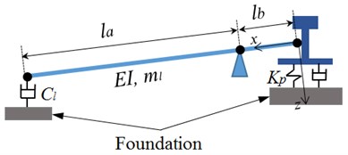
As for the near-end point of the lever, the dynamic equation of the lever system can be written as Eq. (11):
where, , are bending stiffness and linear density of the lever; is the vertical displacement vector of the lever, and it can be obtained by Eq. (12):
where, represents the vertical displacement relative to the rail. The boundary condition of the Eq. (11) can be obtained as:
The Ampere force presented in Eq. (9) is equivalent to the damping force to be applied to the far-end of the lever, as in Eq. (14). Therefore, the equivalent damping coefficient in the right side of Eq. (14) can be written as Eq. (15):
It can be seen from Eq. (15) that the damping coefficient is proportional to the squared values of the magnetic field intensity and length of the rigid wire, and inversely proportional to the applied resistance. For an open circuit, that is, 0 and for a short circuit if the internal resistance is discounted. In Section 3, the enhancement performance is analyzed using instead of the resistance .
The output power can be obtained through Eq. (16):
3. Experiment
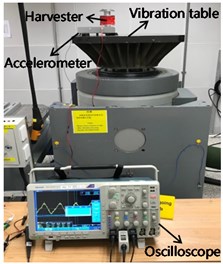
For testing the change trend of the energy harvester with the different excitation displacement, the testing equipment was shown in the Fig. 6. Two static magnets are respectively fixed to the upper and lower aluminum bushings. The upper and lower aluminum bushings are mechanically connected to the polymethyl methacrylate tube. Between the two static magnets, a floating magnet is placed at the center of the tube, and the magnetic pole direction of the magnet is set to repel the central floating magnet, so that the central magnet is suspended in the tube. The distance between the floating magnet and the stationary magnet can be adjusted. The tube is fixed to the support together with the support ring. The energy harvester is mounted on a vibration table with rigid clips. One integrated electronic piezoelectric (IEPE) accelerometer is utilized to control the vibration amplitude. Table 1 shows the parameters of the vibration table system and the IEPE accelerometer (PCB353B03) utilized by the control system. A power cabinet provides a power supply to the vibration table, and an industrial PC displays the software interface of the vibration controller. The vibration acceleration of the rail is transmitted to the fixed support, and the excitation of the vibration harvester further stimulates the dynamic response of the suspended magnet. The test was designed in seven cases: the displacement amplitude of excitation changes from 4 to 16 mm (interval 2 mm), and the vibration frequency was set to 10 Hz. Integrated electronic piezoelectric accelerometers are set to control the vibration excitation of the vibration table. An oscilloscope (Tektronics DPO4014) with a voltage probe of 10X attenuation was connected to the coils of the harvester. The sampling data from the oscilloscope were recorded and transferred to a local computer for subsequent analysis.
Table 1Parameters of vibration test system
Performance | Value | Unit | Performance | Value | Unit |
DC3200-36 vibration test system | PCB 353B03 accelerometer | ||||
Normal rated thrust | 32000 | N | Sensitivity (±5 %) | 9.7 | mv/g |
Maximum displacement | 20 | mm | Measurement range | ±500 | g |
Maximum velocity | 2 | m/s | Frequency range (±5 %) | 1-7000 | Hz |
Maximum acceleration | 19 | g | Resonant frequency | ≥ 38 | kHz |
Minimum frequency | 5 | Hz | Broadband resolution | 0.003 | g/rms |
Maximum frequency | 2000 | Hz | Non-linearity | ≤ 1 % | – |
Fig. 6The testing equipment
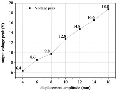
The output voltage peak of the harvester with different excitation was shown in Fig. 7. The value of output voltage peak increase with the displacement amplitude of excitation, and this trend agrees well with the Eq. (6). Therefore, in the following parts, we study the efficiency and performance of the enhanced energy harvester.
Fig. 7The output voltage peak of the harvester with different excitation
4. Results and performance of the EEH
In this section, the influence of the three main parameters, the leverage ratio, stiffness of the lever and the equivalent damping coefficient , on the performance of the lever system are analyzed in detail. The parameters of vehicle and track are given in Table 2 and Table 3, respectively.
Table 2Dynamic parameters of the high-speed passenger vehicle
Parameters | Value | Unit |
Vehicle body mass, | 34 | t |
Wheelset mass, | 1.4 | t |
Bogie mass, | 3.0 | t |
Vehicle body inertia, | 2278 | t·m2 |
Bogie inertia, | 2.71 | t·m2 |
Primary suspension stiffness | 1100 | kN·m-1 |
Primary suspension damping | 12 | kN·S/m |
Secondary suspension stiffness | 800 | kN·m-1 |
Secondary suspension damping | 160 | kN·S/m |
Bogie spacing, 2 | 18.0 | m |
Wheelset spacing, 2 | 2.4 | m |
Table 3Dynamic parameters of the ballasted track
Track parts | Parameters | Value | Unit |
Rail | Bending stiffness, | 6.62×10⁶ | N·m2 |
Linear density, | 60.64 | kg/m | |
Railpad system | Railpad stiffness, | 25 | kN/mm |
Railpad damping, | 2.5×10⁴ | N·s/m | |
Sleeper spacing, | 0.6 | m |
4.1. Power Amplification Factor
To describe the performance of the lever system, the Power Amplification Factor (PAF) is defined as the ratio between the output power with and without the lever system, as presented in Eq. (17):
where, the subscript 1 represents the output with the lever system and the subscript 0 represents that without lever system. The energy harvester is mounted directly on the rail flange. Since it shares the same parameters of the energy harvesters to be compared in this section, the equivalent damping coefficients and for the two conditions do not change, that is, . Then, the PAF equals the square of velocity ratio . Additionally, we use the root mean square of the velocity in a time period instead of using at some particular time point . Finally, we obtain the PAF as in Eq. (18):
where, indicates the r.m.s of .
4.2. Velocity wave form comparison
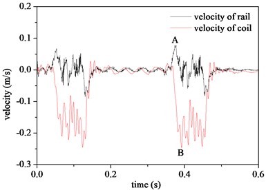
The comparison of velocity wave forms of the rail and energy harvester is given in Fig. 8. It can be seen from Fig. 8 that the velocity of the energy harvester is amplified when the leverage ratio 4.
Fig. 8Comparison of velocities of rail and energy harvester with leverage ratio of 4. (Default parameters: EI= 1000 and Cl= 100)
4.3. The optimum condition
It is reasonable that the PAF should be for a rigid lever with a leverage ratio of . However, the focus of this section is on the PAF performance when using an elastic lever. The results of PAF with different leverage ratios considering different lever stiffness and equivalent damping coefficients are illustrated in Fig. 9 and Fig. 10, respectively.
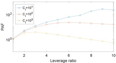
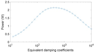
It can be seen from Fig. 9(a) that the PAF does not always show the expected upward trend as the leverage ratio increases. Instead, a trend of first increase and then decrease can be observed, especially with the large damping coefficient. For a given and , the optimum leverage ratio is the one that maximizes PAF; for example the optimum leverage ratio is 6 when 100 and 1000 in Fig. 9(a). Fig. 9(b) shows that the output power first experiences an upward trend and then goes down as increases, and the optimum output power is about 2.15 W. When 0, a case of an open circuit of the EEH, the output power is of course 0, while for , a case of a short circuit of the EEH, the far-end of the lever receives great damping force and the velocity becomes quite small, which in turn reduces the output power of the energy harvester. The optimum output power of the EEH can be reached when the load resistance equals the equivalent internal resistance (not the internal resistance inside the energy harvester).
Fig. 9a) The influence of the leverage ratio on the PAF considering different equivalent damping coefficients, where Cl= 10, 100 and 1000 with EI= 1000, b) the output power versus the equivalent damping coefficients, where EI= 1000 and rl= 10
a)
b)
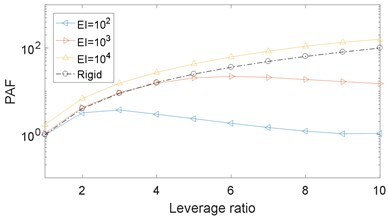
From Fig. 10(a), it is obvious that there exists an optimum leverage ratio for a given lever stiffness; for example, the optimum leverage ratio is 3 when 100 and 100 in Fig. 10(b), and a smaller or larger leverage ratio leads to worse performance. An interesting finding is that when 1e4, the PAF is greater than for a leverage ratio ; for example, PAF = 159 > 102 for leverage ratio 10. For a fixed leverage ratio 10, the PAF results with different lever stiffness between 1.2e4 and 1.31e4 are given in Fig. 10(b). It is found that the PAF reaches a peak value at 430.2 when 1.29e4. The value of 430.2 is much greater than the expected 100 for a rigid lever.
Fig. 10The influence of the leverage ratio on the PAF considering different lever stiffness: a) illustrates different lever stiffness, EI= 1e2, 1e3 and 1e4 with Cl= 100, b) is obtained with a fixed leverage ratio rl= 10 and Cl= 100
a)
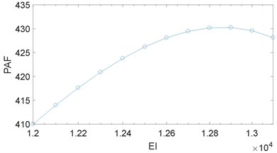
b)
Fig. 11The resonance effect observed when rl= 10. The red dashed line represents the PAF of a rigid lever and rl= 10
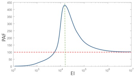
For an elastic lever, the natural vibration frequency is determined with a given leverage ratio, stiffness and mass. When the excited frequency is close to the natural frequency of lever, the displacement as well as the acceleration will increase dramatically. Thus, it is because of the resonance effect that the PAF can be greater than when , as illustrated in Fig. 11. In the case of a vehicle-track coupling system, the vibration of the rail is a broadband excitation, so the resonance effect can be quite useful when designing an EEH.
As a result, using an elastic lever instead of a rigid one is efficient to enhance the performance of an EEH. The amplification effect comes from two aspects, one is the magnifying effect of leverage itself and the other is the resonance effect.
5. The influence of the EEH on vehicle-track dynamics
The EEH is able to transform the mechanical energy of the rail into electric power. A subsequent question is how the EEH will influence the vehicle-track dynamics. Is it possible for the EEH to be used as an approach for vibration reduction?
Comparisons of the wheel-rail force and the acceleration of the rail with and without the EEH are presented in Fig. 12. Contrary to our expectations, it is found that the wheel-rail force is amplified slightly when the EEH is included. The increase of the wheel-rail force indicates the interaction between the wheel and rail is worsened. As for the rail vibration, the influence of the EEH is negligible according to Fig. 12(b). The results show that the EEH does not seem to be a potential rail vibration reduction approach. This can be explained by the following two points:
1) The existence of the EEH changes the periodic supported structure of the track. An equivalent stiffness irregularity is added to the track which will lead to a greater force between the wheel and rail. The increased energy due to the equivalent stiffness irregularity is higher than the mechanical energy that is transformed into electric power. On this point, the EEH may have a negative influence on rail vibration. As a solution, it may be a counter measure to mount many EEHs along the rail periodically, like the fastening system with an interval of 0.6, so the equivalent stiffness irregularity will be eliminated.
2) The parameters of the EEH are quite small compared to the parameters of the vehicle-track system, i.e. the scale of the track is much bigger than the size of the EEH, the weight of the rail is much greater than that of the EEH. This is the reason the EEH only has a slight influence on the vibration of the rail.
In conclusion, even though it seems impractical to use the EEH as an approach for vibration reduction, it will not become a negative factor on the vehicle-track system.
Fig. 12Comparison of: a) the wheel-rail force, b) acceleration of the rail with and without the EEH. (EI= 1e3, Cl= 1e3 and rl= 10)
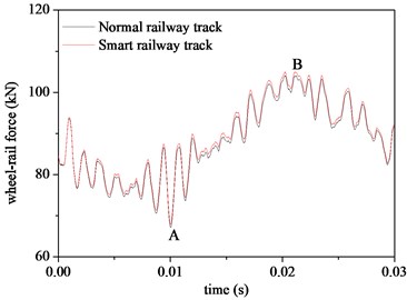
a)
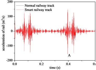
b)
6. Conclusions
An elastic lever system is put forward to enhance the performance of energy harvesting in this paper. To analyze the performance of the EEH, vehicle-track coupling dynamics is applied to simulate the railroad environment. A model of the energy harvester with an elastic lever system is established. The following conclusions have been reached:
1) The output power of the EEH is greater when a lever with a leverage ratio larger than 1 is included. The Power Amplification Factor (PAF) is defined to evaluate the performance of EEH. It is found that the PAF mainly depends on the leverage ratio, the stiffness of the lever and the equivalent damping coefficient. There exists an optimum leverage ratio when using an elastic lever.
2) The resonance effect of the leverage system is observed, which can be quite useful to improve the performance of the EEH. It is found that the PAF can be greater than with a leverage ratio of . For the case presented in Section 3.4, the PAF reaches 430 for a leverage ratio of 10 when the stiffness of lever is 1.3e4 and 100. The amplification effect comes from two aspects, one is the magnifying effect of leverage itself and the other is the resonance effect of the lever.
3) The EEH has a limited influence on the vibration of the rail. As the leverage ratio and lever stiffness increases, the influence is greater. It seems impractical to use the EEH as an approach for vibration reduction. However, it will not become a negative factor on the vehicle-track system.
References
-
Hodge V. J., Keefe S. O., et al. Wireless sensor networks for condition monitoring in the railway industry: A survey. IEEE Transactions on Intelligent Transportation Systems, Vol. 16, Issue 3, 2015, p. 1088-1106.
-
Stephen N. G. On energy harvesting from ambient vibration. Journal of Sound and Vibration, Vol. 293, Issue 1, 2006, p. 409-425.
-
Gao M. Y., Wang P., et al. Self-powered ZigBee wireless sensor nodes for railway condition monitoring. IEEE Transactions on Intelligent Transportation System, Vol. 19, Issue 3, 2018, p. 900-909.
-
Bischoff R., Meyer J., et al. Event based strain monitoring on a railway bridge with a wireless sensor network. Proceeding of 4th International Conference of Structure Health Monitoring of Intelligent Infrastructure, Zurich, Switzerland, 2009.
-
Sekula K., Kolakowski P. Piezo-based weigh-in-motion system for railway transport. Structure Control Heath Monitoring, Vol. 19, Issue 2, 2012, p. 199-215.
-
Nelson C. A., Platt S. R., et al. Power harvesting for railroad track health monitoring using piezoelectric and inductive devices. Proceedings of SPIE 6928: Active Passive Smart Structures Integrated Systems, San Diego, California, 2008.
-
Wang J. J., Penamalli G. P., Lei Z. Electromagnetic energy harvesting from train induced railway track vibrations. Proceedings of 2012 IEEE/ASME 8th IEEE/ASME International Conference on Mechatronic and Embedded Systems and Applications, 2012.
-
Yuan T. C., Yang J., Song R. G., Liu X. W. Vibration energy harvesting system for railroad safety based on running vehicles. Smart Materials and Structures, Vol. 23, Issue 12, 2014, p. 1-14.
-
Gao M. Y., Wang P., et al. Design and verification of a rail-borne energy harvester for powering wireless sensor networks in the railway industry. IEEE Transactions on Intelligent Transportation Systems, Vol. 18, Issue 6, 2017, p. 1596-1609.
-
Datta U., Dessouky S., Pagagiannakis A. T. Harvesting thermoelectric energy from asphalt pavements. Transportation Research Board 95th Annual Meeting, Transportation Research Board, Washington, 2016.
-
Zhai W. M. Vehicle-Track Coupled Dynamics-Fourth Edition. Science Press, Beijing, 2015.
-
Remington P. J. Wheel/rail rolling noise, I: theoretical analysis. The Journal of the Acoustical Society of America, Vol. 81, Issue 6, 1987, p. 1805-1823.
Cited by
About this article

The authors would like to kindly appreciate the support by the National Natural Science Foundation of China (Projects No. 51425804, No. U1234201 and No. 1334203).
