Abstract
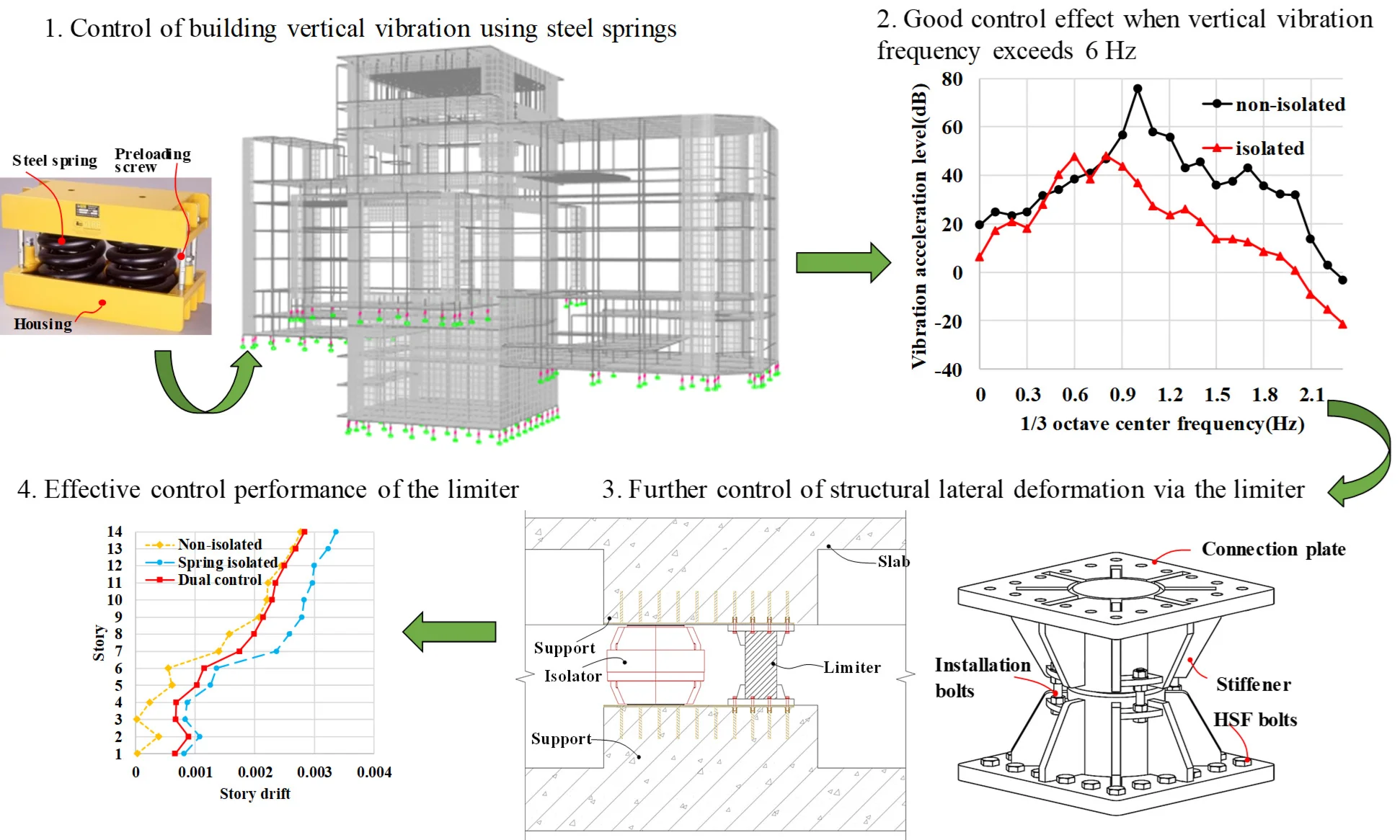
To address both vibration control and seismic safety for metro-adjacent buildings, this paper proposes a vibration-seismic control (VSC) system integrating steel spring isolators and limiters. The isolators mitigate vertical vibration, while the limiters provide lateral stiffness to restrain isolation layer displacement during earthquakes. Taking the Music Conservatory Theatre of the Chinese University of Hong Kong, Shenzhen (CUHK-SZ) as a case study, finite element models of three structural schemes (non-isolated, vibration-isolated, and VSC) are established to compare dynamic responses under rare earthquakes. Results show that steel springs effectively mitigate metro-induced vibrations, reducing the maximum vibration level and secondary noise by more than 20 dB/dB(A). With the integration of limiters, the VSC system retains vertical isolation performance while restricting the inter-story drift ratio to 2 %-3 %, meeting the design requirements. The proposed VSC system achieves synergy between vertical vibration isolation and horizontal seismic resistance, providing a reliable solution for acoustically sensitive buildings adjacent to metro corridors.
Highlights
- A decoupled-designed VSC system combining steel spring isolators and gap limiters is proposed, which realizes efficient vertical isolation against metro low-frequency vibrations and enhances lateral seismic stiffness, overcoming the weak horizontal bearing drawback of traditional isolation systems.
- Engineering verification on CUHK-SZ Music Conservatory Theatre shows the established isolation system (3.5 Hz vertical natural frequency) reduces metro-induced vibration level and secondary noise by over 20 dB, satisfying relevant vibration limits.
- The presented VSC system features low vertical frequency, simple structure, easy construction and low lifecycle cost without routine replacement, applicable to metro podiums, precision labs and other vibration-sensitive buildings.
1. Introduction
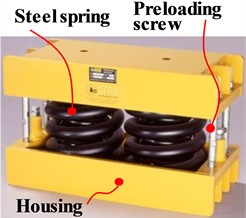
Low-frequency vibrations induced by metro operations propagate through tunnels and surrounding soil, posing threats to residential comfort, precision instruments, and historical structures. In theaters and concert halls, such vibrations may trigger resonance, degrading acoustic performance and disrupting artistic presentations. To mitigate this issue, integral steel spring vibration isolation technology is adopted for theaters adjacent to rail corridors. By leveraging its low natural frequency and high load-bearing stability, this technology enables elastic isolation between the superstructure and the foundation, thereby blocking the transmission paths of low-frequency vibrations. The core principle involves installing steel spring isolators between the superstructure and substructure, enabling the main structure to “float” and converting rigid connections into elastic ones, thus interrupting vibration transmission. Steel springs have been widely used in vibration isolation applications for decades. In 1980, Hüffmann [1] proposed a seismic isolation system integrating coil springs and viscous dampers, aiming to overcome the limitations of rubber bearings in isolating vertical seismic components. In 1992, Tezcan et al. [2] conducted experimental validation on a similar three-dimensional system, demonstrating that the vertical acceleration was reduced to approximately 50 % of the input values. Makris et al. [3] further confirmed its dual capabilities of seismic isolation and vibration control. In 1994, Constantinou et al. [4] tested a composite isolation system incorporating PTFE sliders and steel springs. In 2002, Wagner [5] proposed a steel-spring-based isolation system for urban rail-induced vibrations, reporting a vibration reduction of up to 25 dB in projects such as the London IMAX Cinema. Advancements in vibration-seismic control (VSC) technology have facilitated the development of more sophisticated systems. In 2013, Li et al. [6] developed a three-dimensional seismic isolation bearing (3DSIB) for long-span structures. In 2018, Lee et al. [7] proposed a triple-pendulum friction bearing combined with vertical steel spring-viscous dampers for transformers. In 2020, Shang et al. [8] introduced a low-cost three-dimensional steel spring-asphalt isolation bearing (3D-SAIB) using steel springs and asphalt, tailored for rural buildings. In 2023, Dong et al. [9] developed a long-period vertical variable-stiffness isolator (LVIVS). Between 2022 and 2024, Zhuang et al. [10] proposed precompressed spring devices (PSDs) for single-layer spherical lattice shells, which offer high static stiffness and low dynamic stiffness. In contrast to these innovations, steel spring isolators manufactured by GERB Vibration Control Co., Ltd (Fig. 1) remain widely adopted, owing to their mature technology, cost-effectiveness, ease of installation, and long-term durability. They are extensively utilized in vibration-sensitive facilities such as museums and concert halls. However, their low horizontal stiffness restricts lateral load-bearing capacity, presenting challenges for complex structures or seismically vulnerable buildings. To overcome this, this paper proposes a VSC system consisting of steel spring isolators and limiters. Through a decoupled design, it prioritizes low-frequency vertical isolation for metro-induced vibrations under service conditions, while the limiter engages under earthquakes to restrain lateral drift. Compared to existing solutions, it offers lower vertical frequency, simpler construction, lower lifecycle costs, and no need for component replacement. The method is applicable to metro podiums, sensitive laboratories, precision workshops, data centers, and operating rooms where vibration control is the primary concern.
Fig. 1Steel spring vibration isolator. Photo by Han Yanyan, Qingdao, China, Dec 12, 2024
2. Design of the vibration isolation system
The CUHK-SZ Music Conservatory, located in Shenzhen's International University Park, spans over 70,000 m² and houses acoustically sensitive spaces including a theater, concert hall, recording studios, and music laboratories. Shenzhen Metro Line 21 runs adjacent to the site, with distances of approximately 103 m to the site boundary and 217 m to the theater (Fig. 2). Given stringent acoustic requirements, steel spring vibration isolation technology is adopted for the theater and other buildings. The theater is decoupled from surrounding structures and the basement, connecting only via vibration isolation springs at the base, which reduces vertical vibration frequency and mitigates metro and road environmental vibration impacts. Based on functional layout and floor elevations, the arrangement of the steel spring vibration isolators is shown in Fig. 3.
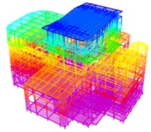
The dominant frequency of metro-induced vibration is 20-100 Hz [11], while long-span floor slabs typically have natural frequencies of 7-10 Hz. Based on vibration isolation principles and similar project experience [12], the vertical natural frequency of the isolation system is designed to be 3.5 Hz. A finite element model is established using SAP2000, with frame beams/columns simulated by beam elements, walls/slabs by shell elements, and steel spring isolators/limiters by Link elements. The stiffness center of the isolation layer is adjusted to align with the superstructure’s mass center based on vertical deformation distribution. To guarantee the computational accuracy of dynamic analysis in the target frequency band, the mesh size of the model is controlled based on elastic wave propagation theory. The shear wave velocity of concrete is about 2000-2500 m/s, which corresponds to a minimum wavelength of approximately 20 m within the vibration frequency range of 20-100 Hz. Accordingly, the characteristic element size for beams, slabs and columns is defined as 1.2 m, roughly 1/16 of the minimum wavelength, satisfying the precision requirement for dynamic time-history analysis. For dynamic input, uniform vertical acceleration excitation is applied at the structural base. Rayleigh damping is adopted to characterize the energy dissipation of the structural system, with the analysis focused on the frequency band of 3-80 Hz. The reference frequencies for Rayleigh damping coefficient calibration are selected as 3 Hz and 80 Hz, both corresponding to a modal damping ratio of 0.05. Dynamic characteristic analysis shows that the 11th, 12th, 14th, and 15th vertical modes have frequencies ranging from 3.02 Hz to 3.52 Hz (Table 1), confirming that the isolation system meets the 3.5 Hz design target. The 11th vertical mode shape is shown in Fig. 4.
Fig. 2Aerial view of the performance theater. Photo by Sun Dianlong, Shenzhen, China, Jan 24, 2024

Fig. 3Schematic diagram of the theater
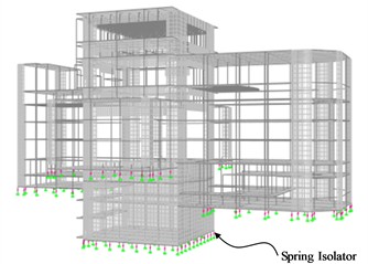
Table 1Vertical modal frequencies
Order | Frequency (Hz) | Modal mass participation coefficient | |||
X | Y | Z | Torsion | ||
11 | 3.022 | 0.002 | 0.000 | 0.029 | 0.001 |
12 | 3.235 | 0.001 | 0.001 | 0.280 | 0.000 |
14 | 3.462 | 0.001 | 0.002 | 0.032 | 0.001 |
15 | 3.519 | 0.002 | 0.004 | 0.008 | 0.003 |
Fig. 411th vertical mode shape
3. Performance of the steel spring vibration isolation system
3.1. Vertical vibration isolation performance
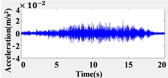
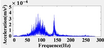
The vibration acceleration time-history curve adopted in this project was used as the vibration source, as shown in Fig. 5. The uniform excitation method was applied at the bottom of the structure, and the vibration response of the structure was calculated and analyzed. The effect of the integral steel spring vibration isolation system was evaluated by comparing the vibration responses under two working conditions: with isolation and without isolation.
Fig. 5Time-history and spectrum diagram
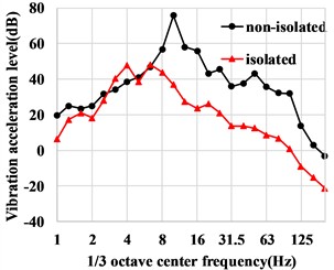
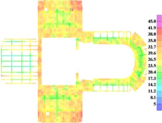
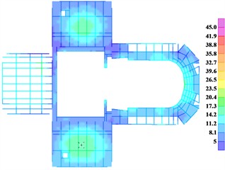
(1) Maximum frequency division vibration level. The maximum frequency division vibration level of the floor slab without vibration isolation ranges from 67.2 to 75.6 dB, all exceeding the limit of 62 dB [13]. The maximum frequency division vibration level of the isolated floor slab ranges from 48.7 to 58.3 dB, which meets the code requirements. The reduction in the maximum frequency division vibration level of each floor slab can reach more than 20 dB, indicating that the steel spring exhibits a very significant effect in vertical vibration isolation. The contour plot of the maximum frequency division vibration level in the auditorium is shown in Fig. 6. The position with the maximum vibration response on the auditorium floor slab was selected to investigate the curve of vibration level with 1/3 octave center frequency, as shown in Fig. 7. It can be seen from the figure that after adopting the integral steel spring vibration isolation measure, the vibration response of each floor is significantly reduced above 6 Hz.
Fig. 6The contour plot of maximum frequency division vibration in the auditorium floor
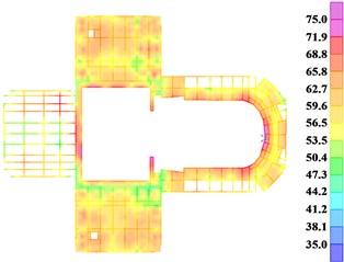
a) Non-isolation
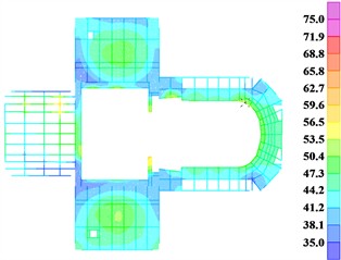
b) Isolation
Fig. 7The curve of vibration level with 1/3 octave center frequency
(2) Secondary noise. The secondary noise from the floor slab of the non-isolated structure ranges from 39.8 to 43.2 dB(A), all exceeding the limit of 35 dB(A) [13]. The secondary noise from the floor slab of the isolated structure ranges from 14.6 to 21.6 dB(A), which meets the code requirements. The noise reduction of each floor slab can reach more than 20 dB(A), indicating that the steel spring exhibits a very significant effect in vertical vibration isolation. The contour plot of secondary noise in the auditorium is shown in Fig. 8.
Fig. 8Contour plot of secondary noise from the auditorium floor slab (dB(A))
a) Non-isolation
b) Isolation
3.2. Horizontal seismic performance
The seismic precautionary intensity of the structure is 7 (0.1 g), the site class is Class Ⅱ, the design earthquake group is the first group, and the site characteristic period is 0.35 s. The mode-superposition response spectrum method (CQC) was used to conduct a comparative analysis between the non-isolated structure and the integrally isolated structure with steel springs. The results are listed in Table 2. Compared with the non-isolated structure, the horizontal period of the isolated structure is prolonged, which is about 1.3-1.4 times that of the former. The base shear of the isolated structure increases slightly due to the additional moment caused by the increased structural rocking, with an increase of 17 % in the -direction and 20 % in the -direction. The story drift ratio of the isolated structure in the - and -directions increase by 19 % and 21 %, respectively.
Table 2Comparison of overall structural indexes
Overall indexes | Period (s) | Base shear (kN) | Maximum Story drift ratio | ||||
T1 | T2 | T3 | |||||
Non-isolated | 0.866 | 0.791 | 0.684 | 7794 | 8369.9 | 1/2441 | 1/2529 |
Isolated | 1.128 | 1.104 | 0.93 | 9127.5 | 10075.6 | 1/2052 | 1/2084 |
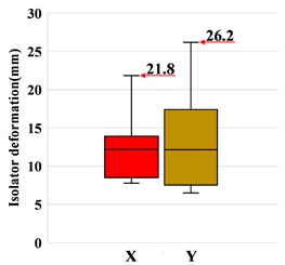
Under rare earthquakes, the lateral deformations of the isolators in the and directions of the isolated structure are shown in Fig. 9. The maximum values are 21.8 mm and 26.2 mm, respectively, both exceeding the acceptable limit of 20 mm for the structure. Therefore, to ensure the lateral stability of the structure, further measures are required to increase the horizontal stiffness of the isolation layer and control its horizontal deformation.
Fig. 9Horizontal deformations
4. Seismic performance analysis of vibration-seismic control system
4.1. Scheme of the vibration-seismic control system
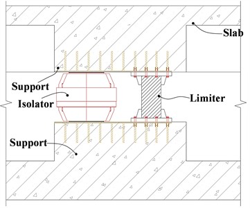
To control excessive horizontal deformation of isolators under rare earthquakes, limiters are introduced to form a VSC system with steel springs. Each limiter consists of a shaft and a sleeve with reserved horizontal (5 mm) and vertical (10 mm) gaps filled with flexible material (5 mm thick), as shown in Fig. 10. The design meets two requirements: (1) under normal service, the limiter provides no vertical stiffness; (2) under earthquakes, it provides vertical stiffness comparable to adjacent vertical members while controlling horizontal deformation to ensure structural safety.
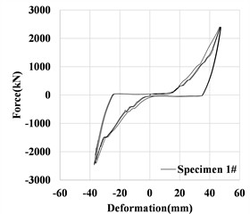
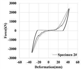
The mechanical performance test of the limiter is shown in Fig. 11. During the loading stage, the closure of gaps in the loading device occurs, resulting in certain differences between the loading curve and the unloading curve. The stiffness is calculated based on the unloading curve, and the design stiffness is taken as the average value of the test results, namely 350 kN/mm. The test results of horizontal stiffness and bearing capacity are listed in Table 3. In SAP2000, the limiter is simulated using a link element with a trilinear constitutive relation. The horizontal segment corresponds to the gap between the limit shaft and the filling material. The two inclined segments correspond to the combined action stage of rubber and steel, and the independent action stage of steel plate after rubber no longer functions, respectively. The stiffness values of the two segments are 100 kN/mm and 350 kN/mm. The constitutive relation of the limiter is shown in Fig. 12.
Fig. 10Schematic diagram of the limiter
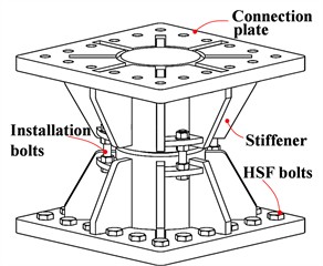
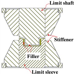
Fig. 11Load-displacement curves of the limiter under mechanical performance test
The limiters are arranged based on two principles: (1) to control horizontal deformation, they are placed at isolators with larger displacement; (2) to enhance torsional resistance, they are arranged bidirectionally along the building perimeter. Following these, 36 limiters are installed in the isolation layer – 8 at -3F, 14 at -2F, and 14 at the 1F mezzanine. The layout is shown in Fig. 13, and the installation schematic of the limiter and isolator is presented in Fig. 14.
Fig. 12The constitutive relationship
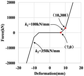
Fig. 13Plan layout of limiters (■: Limiter)
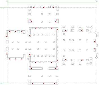
Fig. 14Installation schematic of limiters
4.2. Seismic performance analysis of VSC system under rare earthquakes
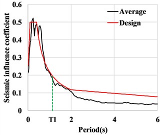
The characteristic period of rare earthquakes is 0.40 s. In accordance with the selection requirements for seismic waves specified in the seismic code [14], two natural waves and one artificial wave were selected. The peak accelerations are input in three directions with ratios of X:Y:Z = 1.0:0.85:0.65 and 0.85:1.0:0.65, respectively. The average response spectrum of the three seismic waves and the design response spectrum are shown in Fig. 15.
Fig. 15Response spectrum
The base shear of the non-isolated, isolated, and VSC structures is shown in Table 3. The comparison shows that after adopting the overall steel spring isolation, the base shear increases slightly by about 12 %-21 % compared with the non-isolated structure due to the increase in structural deformation. When the vibration-isolation and VSC system is adopted, the base shear is basically the same as that of the isolated model.
Under rare earthquakes, the inter-story drift ratios of different control systems are compared in Fig. 16. Compared with the non-isolated structure, the inter-story drift ratio of the isolation system increases by 15 %-21 %. For the vibration-isolation and earthquake-control dual-control system, the inter-story drift ratio only increases by 2 %-3 %, indicating that the limiter plays an important role in controlling the inter-story displacement and deformation of the structure.
Table 3Base shears of non-isolated, isolated and VSC structures under rare earthquakes (kN)
Seismic wave | X | Y | ||||
Non-isolated | Isolated | VSC | Non-isolated | Isolated | VSC | |
Artificial wave | 52640.7(1.0) | 58774.1(1.12) | 59428.6(1.13) | 52200.6(1.0) | 59049.1(1.13) | 59620.1(1.14) |
Natural wave 1 | 47597.8(1.0) | 55407.3(1.16) | 56325.2(1.18) | 52488.9(1.0) | 62009.2(1.18) | 62423.0(1.19) |
Natural wave 2 | 51573.5(1.0) | 60770.3(1.18) | 61183.5(1.19) | 56417.9(1.0) | 68018.(1.21) | 69088.6(1.22) |
Maximum value | 52640.(1.0) | 60770.3(1.18) | 61183.5(1.19) | 56417.9(1.0) | 68018.8(1.21) | 69088.6(1.22) |
Note: The values in parentheses are the ratios of the base shear of the corresponding scheme to that of the non-isolated structure in the same direction | ||||||
Fig. 16Envelope values of story drift ratio under major earthquakes
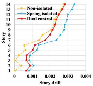
a) direction
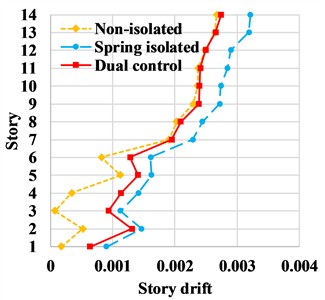
b) direction
Table 4 lists the deformations of steel spring isolators in the isolated and VSC structures under rare earthquakes. The results show that the horizontal deformations of steel spring isolators in the VSC structure are significantly smaller. The maximum horizontal deformations in the and directions are 14.5 mm and 12.3 mm, which are reduced by approximately 23.3 % and 56.9 % respectively compared with the isolated structure, and both are less than the limit value of 20 mm. The minimum vertical compressive deformation of the isolators in the VSC structure is 1 mm, indicating that all isolators are under compression.
Table 4Deformation comparison of different vibration isolation systems (mm)
Seismic wave | Horizontal deformations | Vertical deformations | ||||||||
Isolated | VSC | Isolated | VSC | |||||||
Isolator | Isolator | Limiter | Max | Min | Max | Min | ||||
X | Y | X | Y | X | Y | |||||
Artificial wave | 17.7 | 19.4 | 13.4 | 12.3 | 13.2 | 11.2 | 33.4 | 6.8 | 32.4 | 6.2 |
Natural wave 1 | 18.3 | 12.7 | 14.5 | 10.9 | 14.3 | 10.5 | 32.1 | 7.4 | 31.8 | 7.5 |
Natural wave 2 | 18.9 | 28.5 | 14.2 | 12.3 | 13.6 | 11.2 | 40.7 | 1.4 | 35.1 | 1 |
Maximum Value | 18.9 | 28.5 | 14.5 | 12.3 | 14.3 | 11.2 | 40.7 | 1.4 | 35.1 | 1 |
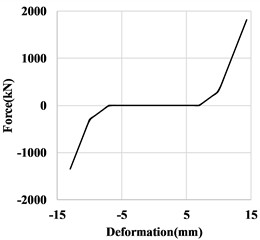
Fig. 17 shows the mechanical behavior curve of the limiter under rare earthquakes. It can be seen that under earthquake action, collision occurs between the inner shaft and the outer sleeve of the limiter, and the limiter achieves its expected function: improving the lateral stiffness of the isolation system. The maximum horizontal force borne by the limiter during the collision is 1815 kN, which is less than its design bearing capacity of 2400 kN. In summary, by adding limiters, the VSC system can effectively improve the lateral stiffness of the steel spring isolation system, control the horizontal deformation of the isolation layer and the structure, place the overall structure and isolators in a more favorable stress state, and ensure the structural safety.
Fig. 17Force-deformation relationship of limiters in the SAP2000 model
5. Conclusions
This paper addresses the challenges of vibration control and seismic safety for subway-adjacent buildings, using the CUHK-SZ Music Conservatory theater as a case study. A vibration-seismic control (VSC) system integrating steel spring isolators and limiters is proposed and systematically investigated. The main conclusions are: (1) The steel spring isolation system (vertical frequency 3.5 Hz) effectively isolates subway vibrations above 6 Hz, reducing floor slab vibration and secondary noise by up to 20 dB compared to the non-isolated structure; (2) With properly gapped limiters, the VSC system achieves dual-function collaboration: limiters remain inactive under normal and frequent earthquake conditions to preserve vertical isolation efficiency, while engaging under precautionary and rare earthquakes to provide additional horizontal stiffness and enhance lateral resistance; (3) The VSC system significantly improves seismic performance: under rare earthquakes, inter-story drift ratio is confined to 2 %-3 %. Maximum isolator horizontal deformation is reduced by 23.3 % (X) and 56.9 % (Y) relative to the isolated structure, with all isolators remaining in compression.
References
-
G. Huffmann, “Spring-damper systems for the support of structures to prevent earthquake damage,” in World Conference on Earthquake Engineering, 1980.
-
S. S. Tezcan and A. Civi, “Efficiency of helical springs and viscodampers in base isolation,” Engineering Structures, Vol. 14, No. 2, pp. 66–74, Jan. 1992, https://doi.org/10.1016/0141-0296(92)90033-m
-
N. Makris and M. C. Constantinou, “Spring-viscous damper systems for combined seismic and vibration isolation,” Earthquake Engineering and Structural Dynamics, Vol. 21, No. 8, pp. 649–664, 1992, https://doi.org/10.1002/eqe.4290210801
-
T. T. Soong and M. C. Constantinou, Passive and Active Structural Vibration Control in Civil Engineering. Vienna: Springer Vienna, 1994, https://doi.org/10.1007/978-3-7091-3012-4
-
H. G. Wagner, “Vibration control systems for trackbeds and buildings using steel springs,” in Proceedings of Acoustics, pp. 99–104, 2004.
-
X. Li, S. Xue, and Y. Cai, “Three-dimensional seismic isolation bearing and its application in long span hangars,” Earthquake Engineering and Engineering Vibration, Vol. 12, No. 1, pp. 55–65, 2013, https://doi.org/10.1007/s11803-013-0151-7
-
D. Lee and M. C. Constantinou, “Combined horizontal-vertical seismic isolation system for high-voltage-power transformers: development, testing and validation,” Bulletin of Earthquake Engineering, Vol. 16, No. 9, pp. 4273–4296, 2018, https://doi.org/10.1007/s10518-018-0311-2
-
S. Shang, Z. Wang, Y. Xiao, and X. Cui, “Experimental and numerical study of the spring-asphalt 3D isolation structures under multi-component ground motions,” Bulletin of Earthquake Engineering, Vol. 18, No. 5, pp. 2461–2496, Jan. 2020, https://doi.org/10.1007/s10518-019-00778-y
-
W. Dong, Y. Shi, Q. Wang, Y. Wang, and J.-B. Yan, “Development of a long-period vertical base isolation device with variable stiffness for steel frame structures,” Soil Dynamics and Earthquake Engineering, Vol. 164, p. 107638, Jan. 2023, https://doi.org/10.1016/j.soildyn.2022.107638
-
P. Zhuang, W. Zhao, and T. Y. Yang, “Seismic protection of a single-layer spherical lattice shell structure using a separated three-dimensional isolation system,” Soil Dynamics and Earthquake Engineering, Vol. 172, p. 108026, Sep. 2023, https://doi.org/10.1016/j.soildyn.2023.108026
-
H. Xia et al., Environmental Vibration Engineering Induced by Traffic. Beijing: Science Press, 2010.
-
B. Zhou et al., “Design studies on Chongqing Renhe Street Primary School teaching auxiliary room subway upper cover,” (in Chinese), Building Structure, Vol. 52, No. S2, pp. 888–893, 2022, https://doi.org/10.19701/j.jzjg.22s2654
-
“Standard for limit and measuring method of building vibration and secondary noise caused by urban rail transit: JGJ/T 170-2009,” China Architecture and Building Press, Beijing, Ministry of Housing and Urban-Rural Development of the People’s Republic of China, 2009.
-
“Code for seismic design of buildings: GB 50011-2010,” China Architecture and Building Press, Beijing, Ministry of Housing and Urban-Rural Development of the People’s Republic of China, 2024.
About this article

The authors have not disclosed any funding.
The datasets generated during and/or analyzed during the current study are available from the corresponding author on reasonable request.
The authors declare that they have no conflict of interest.
