Abstract
In bridge widening, traffic loads can cause different deformations in the new and existing structures, leading to splice joint cracking and reduced performance. This study investigates a simply supported T-beam bridge with an early-strength concrete splice joint. A finite element model in ABAQUS was built to analyze midspan deflection differences under various lane loads and splice joint moduli. The most unfavorable vehicle load position was identified. The study also evaluated traffic control and beam-type shear frames. Results show that closing the lane next to the splice joint reduces the existing bridge deflection by 78 %, and installing shear frames at the two one-third-span positions cuts the deflection difference by 85 %.
1. Introduction
With increasing traffic volume, many expressway bridges are reaching capacity. Widening has become a key strategy to address this issue [1]. The most common method connects the superstructure but keeps the substructure separate, making the splice joint the weakest part [2]. During construction, the splice joint is cast while the old bridge remains in service and the new bridge is not. Traffic loads then cause uneven deformation between the two bridges [3]. Excessive deflection can crack the splice joint, weakening transverse connection, reducing safety, and raising maintenance costs. Early-strength concrete has high early strength, good crack resistance, and low vibration sensitivity [4]. It helps prevent cracking. Therefore, studying the deflection of early-strength splice joints under traffic loads and finding control measures is necessary.
Many scholars have studied the impact of traffic loads on splice joints in bridge widening. Liu et al. [5] proposed a C-shaped steel-concrete composite to enable widening without enlarging the substructure. Zhang et al. [6] reported that magnesium oxychloride cement produces multi-crack failure and improves ductility. Sun [7] noted that shrinkage, creep, and foundation settlement induce extra stresses at the connection. Zhou et al. [8] found that vehicle weight and lateral load position mainly affect differential displacement and vertical velocity.
Deflection in bridge widening can be controlled by traffic restrictions, temporary supports, and tuned mass dampers (TMDs). Du et al. [9] analyzed a T-beam bridge and found that lane closure near the splice joint and a 40 t load limit reduced deflection by 94 %. Kwan and Ng [10] reported a 90 % reduction with a temporary midspan support. Wang et al. [11] showed that traffic restrictions, early diaphragm casting, and staged joint casting all help reduce deflection. Li et al. [12] studied vehicle dynamic loads and proposed control limits for relative deformation and vibration velocity. These, combined with traffic restrictions and staged casting, effectively reduced vibration damage.
Most studies have focused on conventional concrete splice joints, while research on early-strength concrete is limited. This paper examines a simply supported T-beam bridge using finite element simulation and theoretical analysis to study deflection differences of early-strength splice joints under traffic loads. It also evaluates traffic control measures and beam-type shear frames. The findings provide a reference for crack control in engineering practice.
2. Deflection study at the splice joint based on finite element modeling
2.1. Establishment of the finite element model
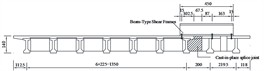
This study focuses on the mainline overpass of the Heyao Interchange. It is a simply supported T-beam bridge with a span of 20 m. Before widening, the bridge was 1575 cm wide. During widening, 50 cm of the existing bridge was cut. A new bridge section, 407.5 cm wide, was then built. The splice joint is 67.5 cm wide. It has a variable thickness: 25.55 cm on the existing bridge side and 20 cm on the new bridge side, as shown in Fig. 1(a). The existing bridge has three lanes, each 3.75 m wide. They are classified by location as the right lane (next to the joint), the middle lane, and the left lane (away from the joint), as shown in Fig. 1(b).
The finite element model developed in ABAQUS is illustrated in Fig. 2.
Fig. 1Schematic diagram of the bridge after widening and the lane position (unit: cm)
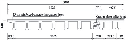
a) The bridge after widening
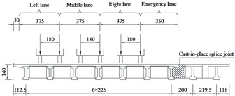
b) Lane position
Fig. 2Bridge model diagram
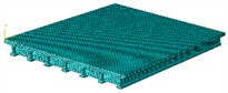
a) Bridge model before widening
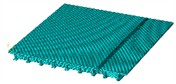
b) Widened bridge model
The old bridge uses C40 concrete, and the new bridge uses C50. They are connected by a rapid-hardening joint made of grout, water, crushed stone, and fibers. Sulfoaluminate cement shortens setting, and fibers enhance tensile strength. The joint concrete modulus is listed in Table 1. The setting interval is 15-25 min. Research shows that the elastic modulus of concrete is zero at the initial setting. It increases linearly until the final setting. In the first hour after final setting, the modulus grows fastest, at 8.6-11.0 GPa/h. After that, the growth rate gradually decreases. For a 15-min interval, the calculated modulus at final setting is 2.72 GPa, lower than measured; thus, the true value is not less than 2.72 GPa.
Table 1Elastic modulus of splice joint concrete (unit: GPa)
Natural curing time after final setting | Condition 1 | Condition 2 | Condition 3 |
1 h | 13.7 | 13.6 | - |
2 h | 17.7±0.5 | 17.8±0.7 | 18.6±0.7 |
3 h | 18.9±0.3 | 19.2±0.7 | 19.6±0.2 |
28 d | 40.2±0.5 | 41.3±0.6 | 40.7±1.2 |
Note: Condition 1 – no vibration after casting; Condition 2 – continuous vibration at 5 Hz and 2.5 cm/s until testing; Condition 3—continuous vibration at 10 Hz and 5 cm/s until testing | |||
In this study, only the period within 3 hours after the joint’s final setting is considered. Therefore, the elastic modulus of the joint concrete is set at 0 GPa, 2 GPa, 4 GPa, …, up to 20 GPa.
It should be noted that the present study is based on a linear elastic material model for concrete. This assumption is commonly adopted for serviceability limit state analysis under vehicle loads, where stresses are expected to be within the elastic range, especially for the critical early-age period of the splice joint. The primary focus here is on comparing deflection differences under various control measures, for which linear analysis provides a consistent and efficient basis for comparison. However, we acknowledge that under extreme loading or if micro-cracking occurs in the splice joint before final setting, material nonlinearity and geometric nonlinearity could become significant. Future research could extend this work by incorporating nonlinear constitutive models to investigate cracking initiation and propagation in the joint, which would provide a more complete picture of the failure mechanisms.
2.2. Model fundamental frequency and impact coefficient
The bridge’s natural frequencies were extracted before and after widening for different splice joint elastic moduli. After removing spurious frequencies, the first natural frequency was taken as the fundamental frequency. When the elastic modulus of the splice joint increased from 2 GPa to 20 GPa, the fundamental frequency of the widened bridge increased by only 0.1 %. For the existing bridge, it increased by just 1.6 %. This indicates that changes in joint stiffness have a negligible effect on the bridge’s fundamental frequency.
According to the specification, the impact coefficient is taken:
The fundamental frequencies were substituted into Eq. (1) to obtain the impact factors of the bridge before and after widening. The results are shown in Table 2. When the splice joint elastic modulus increased from 2 GPa to 20 GPa, the impact factor rose by only 0.07 %. It was 1.04 % higher than that of the existing bridge. This confirms that changes in joint stiffness have a negligible effect on the impact response.
Table 2Impact factors of the bridge before and after widening
Elastic modulus of the splice join / GPa | Existing bridge | 2 | 4 | 6 | 8 | 10 |
Bridge impact coefficient / Hz | 0.27768 | 0.28038 | 0.28043 | 0.28046 | 0.28048 | 0.28050 |
Elastic modulus of the splice join / GPa | 12 | 14 | 16 | 18 | 20 | |
Bridge impact coefficient / Hz | 0.28051 | 0.28053 | 0.28054 | 0.28056 | 0.28057 |
2.3. Vehicle load condition setup
The effects of vehicle loads were analyzed using the superposition principle, based on the linear elastic model. For splice joint elastic moduli from 2 GPa to 20 GPa, the midspan deflection difference across the splice joint and the single-sided deflection of the existing bridge before casting were calculated for each lane load. The midspan deflection difference under multiple-lane vehicle loads was then obtained by superposition.
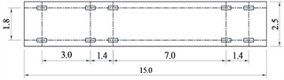
For a single lane, both unrestricted and restricted vehicle loads were considered. In the unrestricted case, a single 55 t vehicle specified in JTG D60-2015 was applied (Fig. 3). In the restricted case, four fully loaded Ford Edge SUVs (axle load 16.2 kN, wheelbase 2.825 m, length 4878 mm) were spaced 1.1 m apart, based on Guo et al. [13] (Fig. 4). To maximize deflection difference, the right wheels were placed at the far-right side of the lane. A Static, General analysis step was used to determine the most unfavorable load position. Step duration was set by Eq. (2), with increment 0.01 s and vehicle speed 10 m/s:
The calculation started when the front wheels entered the bridge. The midspan deflection difference across the splice joint was extracted, and the position with the maximum value was taken as the most unfavorable load position.
Fig. 3Vehicle load model for a 55 t heavy truck (load unit: kN; dimension unit: m)
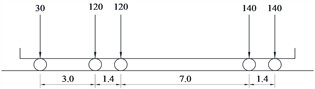
a) Facade layout
b) Plane size
Fig. 4Elevation view of the vehicle load model for the weight-restricted lane (unit: m)
2.4. Validation of the finite element model
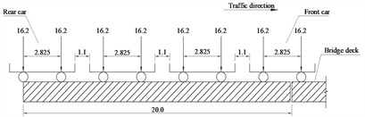
Vibration pickups were installed on the existing bridge of the 20 m mainline overpass at Heyao Interchange (right line) to record velocity time-history data. The recorded data were then transformed into the frequency spectrum shown in Fig. 5. The measured fundamental frequency was 5.313 Hz, close to the 5.317 Hz from the finite element model, with a relative error below 1 %, confirming model accuracy.
Fig. 5Frequency spectrum of the 20 m Heyao Interchange mainline (right line)
2.5. Finite element analysis results
When loads are applied on the right or middle lane, the most unfavorable load position remains unchanged. The midspan deflection difference across the splice joint decreases sharply once the joint modulus reaches 2 GPa, with reductions of 92 % and 83 % under right- and middle-lane loading. Further increasing the modulus to 20 GPa brings only minor additional improvement (37 % and 4 %-5 %). Regardless of the modulus, vehicle weight restrictions reduce the deflection difference by 83 %-84 %, demonstrating their strong effectiveness. Under left-lane loading, the most unfavorable position also remains unchanged. Before widening, the existing bridge near the joint shows negative deflection, meaning traffic does not increase deformation. After casting, once the modulus exceeds 2 GPa, the deflection becomes positive, indicating that the splice joint enhances the lateral connection between the new and existing bridge.
The deflection analysis under simultaneous loading of all three lanes is presented below. Before widening and after widening with splice joint moduli of 2-20 GPa, restricting vehicle weight reduces the midspan deflection difference by 83 %-84 % compared to unrestricted lanes. This demonstrates that weight limits on all lanes can effectively reduce deflection differences and lessen traffic load effects on the joint.
3. Measures to reduce the adverse effects of vehicle loads on the splice joint
3.1. Implementation of traffic control measures
Traffic control schemes are formulated based on the typical lane arrangement rules in China, as shown in Table 3.
Table 3The traffic control project
Serial number | Scheme 1 | Scheme 2 | Scheme 3 | Scheme 4 |
Description | The right and middle lanes have no weight limit, while the left lane is restricted to a maximum weight of 3.24 t (SUV) | The right lane has no weight limit, while the middle and left lanes are limited to 3.24 t (SUV) | Close the right lane, while the middle and left lanes have no weight limit. restriction | Close the right lane, the middle lane has no weight limit, and the left lane is limited to 3.24 t (SUV) |
The analysis shows that combining midspan deflection differences for all three lanes, Scheme 1 is similar to taking no measures, while Schemes 3 and 4 give similar results. Under Scheme 3, the deflection on the existing bridge side near the splice joint before casting is reduced by 78 %. When the joint modulus is 2-20 GPa, the midspan deflection difference decreases by 39 %-54 %, confirming that closing the right lane effectively controls deflection.
3.2. Installation of beam-type shear frames
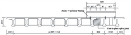
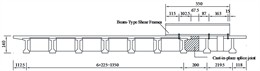
This study compares five beam-type shear frame control schemes. In Schemes 1, 2, and 3, the shear frames are placed at two locations, each at one-third of the span. These schemes share the same anchoring bolt positions and the same contact length with the new bridge. In Scheme 1, the contact length with the existing bridge is the shortest. In Scheme 3, this length is 1 m longer than in Scheme 1, as shown in Fig. 6. Schemes 1, 4, and 5 have shear frames at the same lateral location but different longitudinal spacing. The longitudinal positions of the frames for each scheme are shown in Fig. 7.
Fig. 6Transverse arrangement of beam-type shear frames (unit: cm)
a) Scheme1, 4, 5
b) Scheme 2
c) Scheme 3
Fig. 7Longitudinal arrangement of beam-type shear frames (unit: cm)
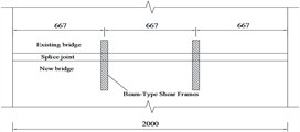
a) Scheme 1, 2, 3
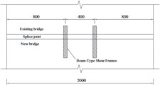
b) Scheme 4
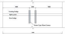
c) Scheme 5
The superposition principle is used to analyze vehicle load effects with the linear elastic model. For joint moduli of 2-20 GPa, the midspan deflection difference and the existing bridge’s single-sided deflection before casting are calculated for each lane. Superposition then gives the deflection difference under multiple-lane loading.
For Schemes 1-5, the most unfavorable vehicle load positions are similar to those without control measures. Before casting, Scheme 1 reduces the midspan deflection difference by 78 %, Scheme 2 lowers it by 85 % due to better restraint of existing bridge rotation, and Scheme 3 achieves an 85 % reduction, slightly less than Scheme 2. Increasing the steel beam end distance beyond 0.65 m from the anchoring bolts does not improve restraint. After the joint modulus exceeds 2 GPa, improvements are minimal, indicating a well-established lateral connection. For Schemes 4 and 5, the maximum deflection difference is not always at midspan. Calculations show that before casting, the maximum difference for Schemes 1, 4, and 5 differs by less than 3 %, and within 1 % for joint moduli of 2-20 GPa, indicating that longitudinal spacing has little effect. The steel beam end should be positioned 0.65 m from the existing bridge anchoring bolts.
4. Conclusions
This paper establishes an ABAQUS model of a simply supported T-beam bridge, including the existing bridge, the widened bridge, and the splice joint, to study deflection at the joint. In addition, it analyzes the effectiveness of traffic control measures and beam-type shear frames in reducing the deflection difference across the splice joint. The main conclusions are as follows:
1) The splice joint modulus has little effect on the widened bridge’s fundamental frequency. At 20 GPa, the frequency rises only 0.1 % from 2 GPa and 1.6 % from the existing bridge.
2) The splice joint modulus and vehicle weight limits strongly affect midspan deflection. Below 2 GPa, the deflection drops most. Higher moduli give little further reduction. Weight limits cut deflection by 83 %-84 %, showing strict control effectively reduces joint stress.
3) Closing the right lane greatly reduces deflection across the splice joint. Before casting, it cuts midspan deflection on the existing bridge side by 78 %. For splice joint moduli of 2-20 GPa, the reduction is 39 %-54 % compared to no measures.
4) Using beam-type shear frames, placing the end 0.65 m from the existing bridge’s anchoring bolts reduces midspan deflection difference the most, by up to 85 %. Therefore, it is recommended to position the shear frame end 0.65 m from the anchoring bolts.
References
-
W. Wu, H. Zhang, Z. Liu, and Y. Wang, “Numerical analysis on transverse splicing structure for the widening of a long multi-span highway concrete continuous box girder bridge,” Materials, Vol. 15, No. 19, p. 6805, Sep. 2022, https://doi.org/10.3390/ma15196805
-
B. Gu, F. Y. Zhou, W. Gao, F. Z. Xie, and L. H. Lei, “Temperature gradient and its effect on long‐span prestressed concrete box girder bridge,” Advances in Civil Engineering, Vol. 2020, No. 1, p. 59562, Aug. 2020, https://doi.org/10.1155/2020/5956264
-
M. Du, M. Shi, C. Liu, B. Lai, and L. Yu, “Simulation study of short-time interruption traffic conditions for bridge widening project,” in Global Conference on Robotics, Artificial Intelligence and Information Technology (GCRAIT), pp. 753–756, Jul. 2022, https://doi.org/10.1109/gcrait55928.2022.00161
-
R.-U.-D. Nassar, A. Balachandra, and P. Soroushian, “Enhanced mechanical performance of high-early-strength concrete with basalt macro-fibre reinforcement for rapid repair and construction applications in airfield pavements,” International Journal of Pavement Engineering, Vol. 26, No. 1, p. 25255, Dec. 2025, https://doi.org/10.1080/10298436.2025.2525523
-
S. Liu, F. Wang, L. Zhu, X. Liu, and X. Su, “Application of C-clamp shaped steel-concrete composite structure in bridge widening,” Bridge Construction, Vol. 54, pp. 21–27, 2024.
-
L.-F. Zhang, J. Yan, H.-Y. Ma, H.-F. Yu, Y. Wang, and Q.-Q. Mei, “Experimental study on magnesium sulfate cement concrete splices of widened box girder,” KSCE Journal of Civil Engineering, Vol. 25, No. 12, pp. 4742–4750, Dec. 2021, https://doi.org/10.1007/s12205-021-1963-z
-
C. Sun, “Research on concrete box girder bridge widening based on spatial grid model,” in IABSE Congress, New Delhi 2023: Engineering for Sustainable Development, Vol. 23, pp. 699–704, Jan. 2023, https://doi.org/10.2749/newdelhi.2023.0699
-
J. Zhou, Z. Zhou, L. Zhang, J. Zhang, and X. Shi, “Traffic-induced vibrations at the wet joint during the widening of concrete bridges and non-interruption traffic control strategies,” Computers and Concrete, Vol. 32, No. 4, pp. 411–423, Oct. 2023, https://doi.org/10.12989/cac.2023.32.4.411
-
J. Du, G. Zhao, Y. Zhao, and X. Hui, “Control of deflection difference between existing and new decks duringbridge widening (in Chinese),” (in Chinese), Journal of Chang’an University (Natural Science Edition), Vol. 31, No. 4, pp. 58–62, 2011, https://doi.org/10.19721/j.cnki.1671-8879.2011.04.011
-
A. K. H. Kwan and P. L. Ng, “Reducing damage to concrete stitches in bridge decks,” Proceedings of the Institution of Civil Engineers – Bridge Engineering, Vol. 159, No. 2, pp. 53–62, Jun. 2006, https://doi.org/10.1680/bren.2006.159.2.53
-
X. Wang, Y. Liu, C. Liu, M. Shi, and L. Yu, “Numerical simulation of practical control measures of deflection difference in bridge widening,” in International Seminar on Computer Science and Engineering Technology (SCSET), pp. 462–465, Apr. 2023, https://doi.org/10.1109/scset58950.2023.00108
-
Q. L. Li, C. Yang, Z. Li, and Y. Li, “Controlling countermeasures for adverse effect of vibration on widening bridge splice joints due to moving vehicle,” Science Technology and Engineering, Vol. 24, pp. 14424–14431, 2024, https://doi.org/10.12404/j.issn.1671-1815.2401146
-
T. Guo, A. Li, and D. Zhao, “Multiple-peaked probabilistic vehicle load model for highway bridgereliability assessment (in Chinese),” (in Chinese), Journal of Southeast University (Natural Science Edition), Vol. 5, pp. 763–766, 2008, https://doi.org/10.3969/j.issn.1001-0505.2008.05.005
About this article

The authors would like to gratefully acknowledge the financial support by Shanxi Transportation Holdings Group Co., Ltd. (23-JKKJ-18).
The datasets generated during and/or analyzed during the current study are available from the corresponding author on reasonable request.
The authors declare that they have no conflict of interest.
