Abstract
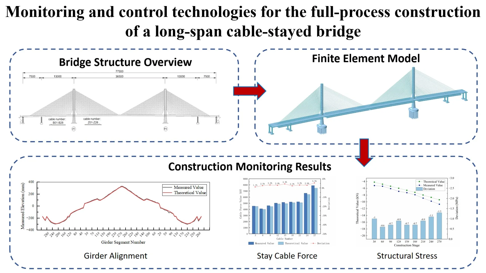
This study focuses on a double-tower, double-plane prestressed concrete cable-stayed bridge with a span arrangement of 75+130+365+130+75 m. A full-bridge finite element model was developed using Midas Civil, and a monitoring system was established to track main girder alignment, cable forces, and structural stresses. A phased control and monitoring strategy is implemented: alignment control is prioritized during the cantilever casting stage, while cable force and stress control take precedence during the closure stage. Monitoring results indicate that the alignment of the completed bridge's main girder is smooth, with cable force deviations controlled within 10 %, and stresses in both the main girder and pylons remaining within safe limits. This study integrates dynamic control and monitoring strategies, offering practical references for the construction control of similar bridges.
Highlights
- Alignment control: Elevation deviations at closure segments were 9.2–17.3 mm; final as‑built main girder elevation ranged from –29 mm to +12.2 mm, well within the ±L/3000 limit, ensuring a smooth completed bridge profile.
- Cable force control: After secondary adjustment, all stay‑cable force deviations were within 5.5% (≤10% code limit), with uniform distribution and sufficient safety reserve.
- Stress and tower deviation: Measured stresses remained compressive (deviations ≤2 MPa from theoretical values), and maximum tower top deviation was only 3.2 mm, confirming structural safety throughout construction.
1. Introduction
Long-span prestressed concrete cable-stayed bridges are crucial in modern bridge engineering. With advancements in analytical tools and construction techniques, cable-stayed bridges have come to occupy a significant position in contemporary bridge engineering due to their exceptional spanning capacity, elegant architectural form, and favorable structural performance [1]. However, during construction, the structural system, internal force state, and geometric alignment of such bridges undergo dynamic changes, exhibiting significant time-dependent characteristics [2]. This results in notable discrepancies between the structural behavior during construction and the ideal completed state, posing severe challenges to construction control. To ensure structural safety during construction and accurately achieve the designed internal forces and alignment of the completed bridge, establishing a systematic, precise, and efficient construction monitoring system is crucial [3].
Despite the extensive research achievements by scholars both domestically and internationally on the construction control of cable-stayed bridges [4]-[5], including recent advances in vision-based monitoring [5] and cable force identification [6], achieving efficient and precise dynamic coordination among multiple control objectives, such as the alignment of the main girder, structural internal forces, and cable forces, remains a key technical challenge in the construction control of such bridges due to their complex coupling relationships. Furthermore, monitoring strategies have also been integrated into broader contexts such as long-term structural health assessment [7] and seismic retrofit design [8], highlighting the versatility of monitoring techniques in bridge engineering. To address these challenges, this study adopts an integrated real-time monitoring and finite element simulation approach. This paper takes a long-span prestressed concrete cable-stayed bridge as a case study to investigate key technologies for whole-process construction monitoring. Unlike post-construction verification methods, this approach offers: (1) higher efficiency – real-time feedback minimizes downtime by enabling immediate deviation correction; (2) improved accuracy – dynamic adjustments keep alignment and forces consistently close to design targets; and (3) broad applicability – the framework can be adapted to other long-span cable-stayed bridges.
2. Project overview
2.1. Bridge structure overview
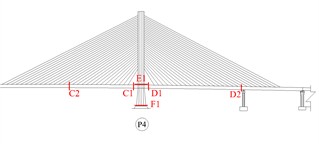
The research object of this paper is a long-span prestressed concrete cable-stayed bridge with a main bridge span arrangement of (75+130+365+130+75) m, featuring a twin-tower and double-cable-plane structure, as shown in Fig. 1. The bridge is semi-floating, with a total main girder length of 775 m divided into 119 segments. The main girder is a C55 prestressed concrete box girder of constant height, measuring 4 m. The prestressed steel strands within the box girder are low-relaxation strands with a nominal diameter of 15.20 mm and a standard tensile strength of 1860 MPa. The total height of the pylon is 119.788 m. The stay cables are anchored at the central saddle of the main girder, with a numbering rule that increases outward from the main tower as the reference point. The cable closest to the tower is numbered Cable 1, and the farthest is numbered Cable 28. The stay cables and the girder segments to which they are anchored have the same numbering.
The main construction process for the bridge includes: erecting supports on Pier 0 of the main girder for segmental casting of the bridge towers; symmetrically cantilever casting segments 1 to 28 of the main girder using form travelers. The system conversion is completed following a closure sequence of side spans, followed by the mid-span. After the completion of the second-phase dead load construction, a secondary cable adjustment is performed on all stay cables of the bridge to ensure that the internal forces of the completed bridge reach an optimal state.
Fig. 1Overall layout diagram of the cable-stayed bridge. Photo taken by Xiaotang Wang at Guangzhou, Guangdong, China on 4 April 2024
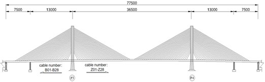
a) Schematic diagram of the main bridge
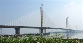
b) Overall view of the entire bridge
2.2. Structural characteristics
The single-column high tower and central double-cable-plane system adopted by this cable-stayed bridge, while aesthetically pleasing, exhibit relatively weaker lateral and torsional stiffness than A or H-shaped bridge towers. Any asymmetric distribution of construction loads or differences in stay cable forces can generate significant additional bending moments in the single-column tower, thereby affecting the intended alignment of the main girder. Therefore, construction monitoring must focus on the coordinated control of the main girder alignment, stay cable forces, and structural stresses.
Furthermore, due to the large span of the cable-stayed bridge, the effects of concrete shrinkage and creep, as well as the secondary internal forces and deformations induced by thermal actions, cannot be overlooked. These effects must be compensated for through precise simulation calculations and by setting appropriate camber during formwork erection.
Therefore, to ensure construction safety and the quality of the completed bridge, establishing a strict and comprehensive construction monitoring system is crucial.
3. Structural finite element model
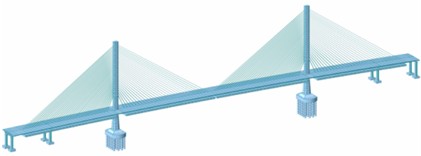
To accurately simulate the entire construction process of the cable-stayed bridge and predict its structural behavior, a spatial finite element model of the entire bridge was established using Midas Civil software, as shown in Fig. 2. The model consists of 1709 nodes and 1634 elements. The main girder and main tower are simulated using beam elements, while the stay cables are simulated using truss elements. The element types and boundary conditions were selected based on the actual structural characteristics to ensure simulation accuracy. A total of 81 construction stages are divided. The material parameters used in the model are assigned based on data collected during construction. Regarding boundary conditions, the bottom of the main tower is fixed; an elastic connection is set between the main girder and the main pier, with the elastic connection parameters determined based on the actual conditions of the bearings; vertical and transverse restraints are applied at the transition piers and side piers. The load effects considered include structural self-weight, second-phase dead load, prestress effects, concrete shrinkage and creep, system temperature rise and fall, solar temperature differentials of the tower, temporary construction loads, and vehicle loads.
Fig. 2Overall finite element model
4. Construction monitoring and results analysis
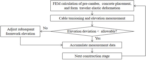
Given the characteristics of this cable-stayed bridge, a whole-process dynamic construction monitoring method is adopted. The construction monitoring objectives focus on alignment control during the cantilever casting stage, supplemented by stress control and stay cable force control; during the closure stage, the focus shifts to stay cable force control and stress control, supplemented by alignment control. The measured data include the alignment of the main girder, stay-cable forces, stresses in the main girder and tower, and deviations in the main tower. The dynamic feedback control process is illustrated in Fig. 3.
Fig. 3Workflow of construction monitoring and control
4.1. Girder alignment
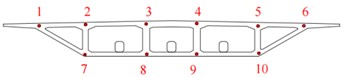
Girder alignment is the primary monitoring focus during the cantilever casting stage and is controlled through the setting of pre-camber. The pre-camber values are initially determined via forward iteration analysis based on the stress-free state control method, aiming to offset cumulative displacements induced by structural self-weight, construction loads, and concrete shrinkage and creep. During construction, the pre-camber for upcoming segments is dynamically adjusted based on measured alignment data from completed segments. Alignment measurement points are located on the top of the girder, with five points arranged per cross-section (Fig. 4).
Monitoring indicates that the main girder alignment progressed smoothly without abrupt changes. The closure accuracy, a key control indicator, was satisfactory. As shown in Table 1, all measured elevation differences at the closure segments met the allowable limits specified in the code [9], demonstrating precise elevation control during cantilever construction.
Table 1Elevation monitoring results at closure segments
Location | Segment number | Elevation (m) | Elevation difference (mm) |
P3 Pier Side-Span Closure | 28B | 24.1627 | 9.2 |
30B | 24.1535 | ||
P4 Pier Side-Span Closure | 28B | 24.1462 | 8.8 |
30B | 24.1374 | ||
Mid-Span Closure | P3# 28Z | 28.5986 | 17.3 |
P4# 28Z | 28.5813 |
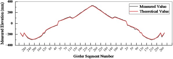
Following secondary cable adjustment, final as-built measurements were taken. The elevation deviations of the main girder ranged from –29 mm to +12.2 mm (Fig. 5), well within the design limit of ±47 mm (±L/3000) and complying with all code requirements. These results confirm the overall smoothness and close conformity of the completed bridge alignment to the design target, validating the effectiveness of the dynamic alignment control strategy.
Fig. 4Layout of alignment measurement points
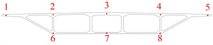
Fig. 5Changes in the alignment of the main girder
4.2. Stay cable force
Cable force control is the primary monitoring object during the closure stage. Stay cable forces are key indicators for evaluating the structural safety and rationality of a cable-stayed bridge system [10]. Considering the significant changes in cable inclination angles and the prominent spatial effects of the stay cables in this bridge, the basic principle of construction control is to achieve a cable force distribution close to the values calculated by the finite element model, thereby determining reasonable initial tensions and tensioning sequences for the stay cables. During construction, the stress-free lengths and tensioning forces of each cable are determined based on the stress-free state method. Cable force measurement and verification are carried out using a dual-control method of jack oil pressure gauge readings and vibration frequency method cable force meters. For each pair of stay cables installed and tensioned, the cable forces of the adjacent five pairs are measured.
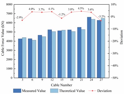
During the initial stages of construction, due to the incomplete formation of the structural system, some stay cables exhibit deviations in their cable forces. After the secondary cable adjustment, the cable force distributions in the side spans and mid-spans of Piers P3 and P4 are uniform, with each cable force close to theoretical expectations. Considering the symmetry of the cable-stayed bridge, only representative cable force data are presented here to avoid redundancy and improve clarity. As shown in Fig. 6, the deviations between the measured and theoretical values of the cable forces for the entire bridge are all controlled within the 10 % allowable range specified by the code. The maximum cable force deviation for Pier P3 occurs at Cable 27 in the side span, with a deviation of 5.5 %. This indicates that the dynamic control strategy for cable forces during the construction process is effective, the stay cable system is under reasonable forces, and has sufficient safety reserves. In addition, the precise control of cable forces minimizes unexpected stress amplitudes under live loads, which is beneficial for the long-term fatigue performance of the cable anchorage zones under cyclic traffic loading. Furthermore, this construction control method establishes a favorable foundation for resisting long-term deformations induced by temperature variations and concrete creep during the bridge's service life, thereby contributing to the structural durability.
Fig. 6Comparison between measured and theoretical values of cable forces
a) Mid span cable forces at Pier P3
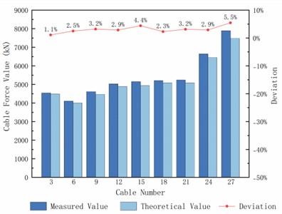
b) Side span cable forces at Pier P3
4.3. Structural stress
Stress control is the primary monitoring object during the closure stage. The tower root cross-section bears the maximum axial force of the entire bridge, while the tower-girder connection section, due to sudden changes in stiffness, experiences complex forces and is prone to stress concentrations. To accurately capture stress changes, long-term strain sensors are installed at the most unfavorable force positions (Fig. 7) during the cantilever construction and closure stages based on the internal force envelope diagram of the entire construction process, calculated by the Midas finite element model. Structural stress responses under self-weight, cable forces, and construction loads at various stages are collected in real-time using a JMZX300 comprehensive test readout instrument. To eliminate interference from temperature strains caused by uneven solar radiation, all stress data from the main tower are measured during temperature-stable periods.
The measurement cross-sections for the main girder are located at Block 0# and Block 20# of the side spans, as well as at Block 0#, Block 14#, and the mid-span of the main girders at Piers P3 and P4. For the two main towers, stress monitoring cross-sections are set at the tower root and near the deck elevation. Each cross-section is equipped with 6 strain sensors, yielding a total of 24 measurement points across the entire bridge.
Given the symmetric nature of the bridge structure and limited space, only the stress variation curves of the main girder at Section C1 and the deck level of the main tower P4 with respect to the construction stages are presented, as shown in Fig. 8. The measured stresses remained compressive throughout construction, confirming that the structure remained in a safe stress state under all construction stages.
Analysis reveals that the stress trends in both the main girder and tower align well with theoretical predictions, showing no abnormal fluctuations. No tensile stresses were detected at any measurement point; all stresses remained compressive with deviations from theoretical values controlled within 2 MPa, significantly below the code's safety limits. These results demonstrate that the adopted construction sequence and monitoring strategy were effective, ensuring the entire structure remained in a safe and controllable state throughout the construction process.
Fig. 7Layout of stress monitoring points layout
a) Longitudinal arrangement
b) Main girder
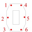
c) Main tower
Fig. 8Stress variation curves of the main girder and the main tower
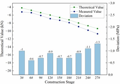
a) Upper edge stress of Cross-section C1
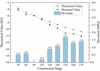
b) Stress at the deck cross-section of Main Tower P4
4.4. Main tower deviation
Deviation monitoring of the main tower focuses on key working conditions that significantly affect the forces and deformations of the tower columns. The controlled monitoring stages include the maximum double-cantilever stage (after the construction of Blocks 7#, 14#, and 21#), after the side-span closure, and after the mid-span closure, during which the asymmetry in cantilever lengths and cable forces is most pronounced. A 360° omnidirectional small prism is set at the top of each main tower as an observation target. The monitoring content is the displacement of the top of the main tower in the longitudinal direction of the bridge.
Table 2Summary of deviations of main towers at various construction stages (Unit: mm)
Construction stage | P3 main tower | P4 main tower | ||||
Measured | Theoretical | Difference | Measured | Theoretical | Difference | |
After 7# cable tensioning | 12.4 | 10.2 | 2.2 | –11.9 | –10.2 | –1.7 |
After 14# cable tensioning | 17.7 | 17.6 | 0.1 | –17.4 | –17.6 | 0.2 |
After 21# cable tensioning | 19.5 | 16.5 | 3.0 | –19.7 | –16.5 | -3.2 |
After side-span closure | –145.4 | –147.7 | 2.3 | 145.8 | 148.6 | -2.8 |
After mid-span closure | –130.7 | –133.4 | 2.7 | 131.2 | 134.2 | -3.0 |
The tracking monitoring results of the deviations of Main Towers P3 and P4 are summarized in Table 2. Analysis reveals that the deviations of the main towers increase slowly and steadily with increasing cantilever length, and the measured values remain very close to the theoretical values, with a maximum deviation of only 3.2 mm, fully meeting code requirements. This demonstrates that the loads and cable forces during construction are effectively controlled, and that the structural deformations are generally consistent with expectations.
5. Conclusions
Throughout the construction of the cable-stayed bridge, the integrated monitoring approach – combining dynamic pre-camber correction, phased control, and the stress-free state method – has proven effective in ensuring construction quality. Upon completion, the cable forces are uniformly distributed with sufficient reserve, structural stresses remain within safe limits, and tower deviations comply with code requirements. The design rationale and control measures adopted herein can serve as a valuable reference for the construction of similar cable-stayed bridges. However, the approach relies on accurate finite element modeling and real-time data acquisition, which require careful calibration. Nevertheless, the methodology is adaptable to other long-span cable-stayed bridges with similar structural characteristics.
The methodology presented in this study also holds broader practical implications for prestressed concrete bridge engineering. For instance, Zheng and Guan [11] demonstrated similar alignment and stress control strategies in the construction monitoring of multi-span prestressed concrete continuous beam bridges, validating the effectiveness of comparing field measurements with theoretical predictions. Furthermore, extending construction monitoring into long-term structural health monitoring, as demonstrated by Hu et al. [12] over 14 years of continuous dynamic monitoring, could provide valuable insights into the effects of environmental factors and long-term service behavior. With the emergence of alternative monitoring technologies such as satellite InSAR [13], future applications could integrate multi-source data for more comprehensive performance evaluation. Therefore, the control framework presented here offers a foundation that can be extended to both similar bridge types and long-term monitoring strategies.
References
-
A. Bayraktar, T. Türker, J. Tadla, A. Kurşun, and A. Erdiş, “Static and dynamic field load testing of the long span Nissibi cable-stayed bridge,” Soil Dynamics and Earthquake Engineering, Vol. 94, pp. 136–157, Mar. 2017, https://doi.org/10.1016/j.soildyn.2017.01.019
-
C. Su, Z. Chen, and Z. Chen, “Reliability of construction control of cable-stayed bridges,” Proceedings of the Institution of Civil Engineers – Bridge Engineering, Vol. 164, No. 1, pp. 15–22, Jan. 2011, https://doi.org/10.1680/bren.900024
-
H. Li and J. Ou, “The state of the art in structural health monitoring of cable-stayed bridges,” Journal of Civil Structural Health Monitoring, Vol. 6, No. 1, pp. 43–67, May 2015, https://doi.org/10.1007/s13349-015-0115-x
-
J. Sun, K. Hui, G. Li, and X. Zhang, “An interpretable framework for wire breakage signal identification in bridge cable health monitoring using linear regression feature fusion,” Structures, Vol. 82, p. 110399, Dec. 2025, https://doi.org/10.1016/j.istruc.2025.110399
-
S. Yu, Z. Xu, Z. Su, and J. Zhang, “Two flexible vision-based methods for remote deflection monitoring of a long-span bridge,” Measurement, Vol. 181, p. 109658, Aug. 2021, https://doi.org/10.1016/j.measurement.2021.109658
-
L.-Y. Luo, Y.-L. Du, T.-H. Yi, C.-X. Qu, and H. Liu, “Cable force identification of cable-stayed bridges considering boundary disturbances using tower-cable-beam responses,” Engineering Structures, Vol. 343, p. 121262, Nov. 2025, https://doi.org/10.1016/j.engstruct.2025.121262
-
W.-H. Hu, D.-H. Tang, J. Teng, S. Said, and R. G. Rohrmann, “Structural health monitoring of a prestressed concrete bridge based on statistical pattern recognition of continuous dynamic measurements over 14 years,” Sensors, Vol. 18, No. 12, p. 4117, Dec. 2018, https://doi.org/10.3390/s18124117
-
A. M. Avossa, D. Di Giacinto, P. Malangone, and F. Rizzo, “Seismic retrofit of a multispan prestressed concrete girder bridge with friction pendulum devices,” Shock and Vibration, Vol. 2018, No. 1, pp. 1–22, Mar. 2018, https://doi.org/10.1155/2018/5679480
-
“Technical Specifications for Construction of Highway Bridges and Culverts,” (in Chinese), Ministry of Communications of the People’s Republic of China, Beijing, JTJ 041-2000, 2000.
-
J. Du, Z. Hong, Y. Chen, Y. Li, J. Song, and Q. Tang, “Research on monitoring technology of cable-stayed bridge,” in Proceedings of the 3rd International Conference on Sustainability in Civil Engineering, pp. 69–75, Jan. 2021, https://doi.org/10.1007/978-981-16-0053-1_9
-
X. Zheng and D. Guan, “Study on construction monitoring and control of multi-span prestressed concrete continuous beam bridge,” Stavební obzor – Civil Engineering Journal, Vol. 33, No. 1, pp. 65–77, Jan. 2024, https://doi.org/10.14311/cej.2024.01.0005
-
W.-H. Hu, S. Said, R. G. Rohrmann, Cunha, and J. Teng, “Continuous dynamic monitoring of a prestressed concrete bridge based on strain, inclination and crack measurements over a 14-year span,” Structural Health Monitoring, Vol. 17, No. 5, pp. 1073–1094, Oct. 2017, https://doi.org/10.1177/1475921717735505
-
P. F. Giordano et al., “Monitoring of a multi‐span prestressed concrete bridge using satellite interferometric data and comparison with on‐site sensor results,” Structural Concrete, Vol. 26, No. 5, pp. 5430–5453, Feb. 2025, https://doi.org/10.1002/suco.202400881
About this article

The authors have not disclosed any funding.
The datasets generated during and/or analyzed during the current study are available from the corresponding author on reasonable request.
The authors declare that they have no conflict of interest.
