Abstract
In this paper, the influence of the deformation of the flexible ring on the performance of the power rolling ring is studied by the finite element simulation method. The results show that the maximum stress of the flexible ring is concentrated in the contact area with the inner and outer conductive rings, and the maximum bending stress increases significantly from 93.5 MPa to 217 MPa with the increase of deformation from 0.3 mm to 0.7 mm. On the other hand, with the increase of deformation, the oscillation of the velocity curve of the probe point on the flexible ring is weakened and tends to be smooth, indicating that the stability of the motion is gradually improved. The research reveals that increasing the deformation can improve the motion stability and also lead to a significant increase in the contact stress, which provides an important basis for the balance design between structural reliability and motion stability of the power rolling ring.
1. Introduction
Rolling electrical transfer components are widely used in rotating systems that require continuous power and/or signal transmission, especially in applications demanding high reliability and long service life. Compared with conventional brush-type slip rings, rolling-contact architectures (e.g., rolling rings and rolling contact connectors) can potentially reduce wear debris and electrical noise by replacing sliding contact with rolling contact, thereby improving transmission stability under certain operating conditions.
Existing studies related to rotary transmission and slip-ring technologies can be systematically organized into four main streams. (1) Alternative slip-ring and non-contact transmission solutions have been proposed to improve signal integrity and mitigate contact-induced disturbances, including optical slip rings for sensor interface applications [1] and multi-channel non-contact transmission methods based on capacitive coupling and quasi-time division multiplexing [2]. (2) Rolling-contact connector technologies and engineering implementations have been documented in patents and industrial technical documents, which outline feasible mechanical configurations and provide design references for practical products [5-8]. (3) Experimental investigations have examined the electrical contact characteristics of rolling contact connectors, providing validation data and insights into contact behavior under different conditions [4]. (4) Numerical and multiphysics modeling has been applied to analyze electrical contact modeling and associated thermal/mechanical effects in roll-ring systems, supporting mechanism interpretation and design-oriented parametric studies [3].
Despite the above progress, the influence of flexible-ring deformation on rolling-ring performance remains a key design challenge. Increasing deformation may enhance kinematic stability and suppress undesirable micro-slip, yet it can also significantly increase local contact stress, which is closely related to wear and reliability. A quantitative, design-oriented understanding of this trade-off under parameterized geometric variations is still insufficient.
To address this gap, this paper establishes a transient finite-element model of a signal rolling-ring assembly in COMSOL Multiphysics. By parameterizing the flexible ring geometry to obtain different deformation levels, we systematically compare motion trajectories and local stress/displacement fields. The results reveal a comprehensive effect of deformation – improved motion stability accompanied by increased contact stress – providing practical guidance for balancing stability and stress constraints in rolling-ring design optimization.
2. Establishment of simulation model of signal rolling ring
Using COMSOL Multiphysics simulation software for simulation analysis, the actual overall design model structure of the signal rolling ring is shown in Fig. 1.
Fig. 1 is the actual overall design model of the signal rolling ring, which is mainly composed of the outer conductive ring, the inner conductive ring and the flexible ring structure. When working, the outer conductive ring is fixed, and the inner conductive ring rotates continuously and drives the flexible ring to roll between the two in the form of rolling friction. The flexible ring is used for rolling friction between the contact parts of the outer conductive ring and the inner conductive ring, so as to realize the function of signal transmission without stranding.
Fig. 1Design model of Signal Roller
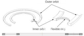
Fig. 2Flexible ring dimensions of the signal rolling ring
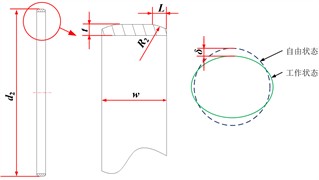
Fig. 3Inner and outer raceway dimensions of the signal rolling ring

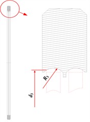
Refer to Fig. 2, the modeling parameters of the flexible ring are as follows: wall thickness 0.25 mm, width = 1 mm, fillet radius 0.8 mm, and arc length = 0.25 mm. The outer diameter of the flexible ring is taken as the independent variable, and the deformation is the response variable. Five sets of values are taken: 19.07, 19.17, 19.27, 19.37, 19.47 mm (step size 0.1 mm), with corresponding values of 0.3, 0.4, 0.5, 0.6, and 0.7 mm, respectively. Refer to Fig. 3, the modeling parameters of the inner raceway are as follows: inner raceway diameter = 84.15 mm, fillet radius = 0.8 mm. Refer to Fig. 3, the modeling parameters of the outer raceway are as follows: outer raceway diameter = 121.15 mm, fillet radius = 0.8 mm.
The free quadrilateral mesh is used to mesh the inner and outer conductive rings, because the motion analysis of the flexible ring is more important during the motion of the signal rolling ring, therefore, the inner and outer conductive rings are meshed by ordinary refined free quadrilateral mesh, and the flexible ring is meshed by more refined free quadrilateral mesh. As shown in Fig. 4.
Fig. 4Subdivision of flexible grid
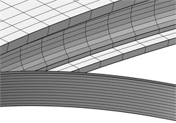
a) Signal rolling ring grid
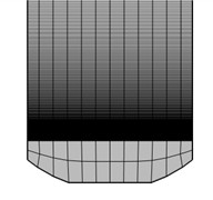
b) Flexible ring cross-section grid
3. Numerical analysis and result discussion
3.1. Analysis of maximum bending stress under different deformations of flexible ring
In the case of ensuring other conditions unchanged, the deformation of the flexible ring is set to 0.3 mm, 0.4 mm, 0.5 mm, 0.6 mm and 0.7 mm, according to the actual situation, H62 brass material is given on the outer and inner conductive rings, and C17200 beryllium bronze material is given on the flexible ring. The whole signal slip ring finally forms an assembly. Setting a certain speed on the inner conductive ring, adding a consistent boundary pair at the contact, and giving the friction coefficient, the transient analysis of the whole model is carried out, and the following results are obtained.
Table 1Material properties
Structure | Material | Density / (kg/m3) | Young’s modulus / (GPa) | Poisson’s ratio |
Inner and outer conductive rings | Brass | 8430 | 105 | 0.34 |
Flexible ring | Plated bronze | 8300 | 125 | 0.3 |
Fig. 5Motion track of Power Roller with deformation
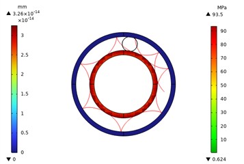
Fig. 6Local stress nephogram of 0.3 power rolling ring
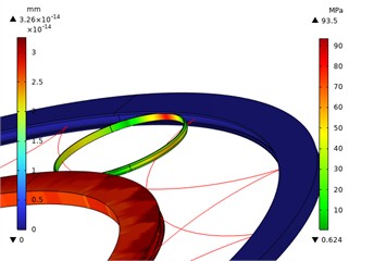
Fig. 5-10 shows the stress and displacement nephograms of the whole and part of the power rolling ring respectively. The inner conductive ring and the outer conductive ring are displacement nephograms, and the flexible ring is stress nephogram. It can be seen from the figure that the maximum stress of the flexible ring occurs at the contact position with the inner conductive ring and the outer conductive ring, and with the increase of the deformation of the flexible ring, the maximum stress of the contact point increases. The red line represents the trajectory of a point on the flexible ring, and the motion is reasonable as a whole. By analyzing the maximum bending stress under different deformations of the flexible ring, it is found that the maximum bending stress of the power rolling ring is the smallest, which is 93.5 MPa, when the deformation of the flexible ring is 0.3 mm, the maximum bending stress of the power ring also increases, reaching a maximum stress of 217 MPa when the deformation is 0.7 mm, which is mainly due to the fact that the larger the deformation of the flexible ring, the more easily the material deforms, the more the elastic deformation of the material occurs, the greater the maximum bending stress of the flexible ring.
Fig. 7Local stress nephogram of rolling ring with 0.4 power deformation
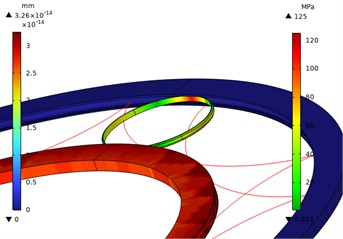
Fig. 8Local stress nephogram of 0.5 power rolling ring with deformation
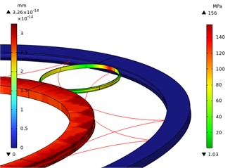
Fig. 9Local stress nephogram of 0.6 power rolling ring with deformation
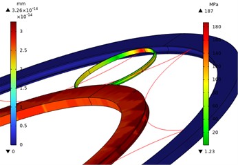
Fig. 10Local stress nephogram of 0.7 power rolling ring with deformation
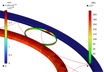
3.2. Velocity variation law under different deformations of flexible ring
Because the rotation and revolution of the flexible ring are carried out at the same time in the working process, the Comsol-based software can not directly extract the rotation speed and revolution speed in the dynamic operation process of the flexible ring, therefore, the extraction of rotation and revolution speed becomes a big difficulty in data processing of rolling ring dynamics simulation. Through velocity analysis, the velocity of the flexible ring is the sum of the velocity of the component and the velocity of the component. Therefore, in order to extract the sum velocity, two points on the flexible ring are used as point probes to measure the velocity of the and components. Finally, the sum velocity can be calculated by setting the global expression of the one-dimensional drawing group.
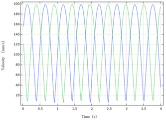
Fig. 11-15 shows the velocity curves of the two probe points on the flexible ring. It can be seen from the figure that the velocity of the two points shows a trend of periodic oscillation and is basically in a stable state. With the increase of the deformation of the flexible ring, the curve becomes smoother, indicating that the motion of the power rolling ring is more stable. Therefore, the velocity variation is reliable.
Fig. 11Curve of deformation 0.3 flexible ring and velocity
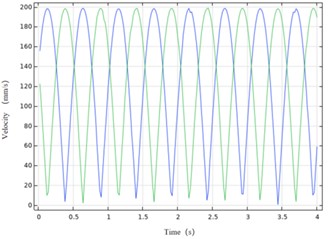
Fig. 12Curve of deformation 0.4 flexible ring and velocity
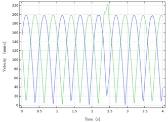
Fig. 13Curve of deformation 0.5 flexible ring and velocity
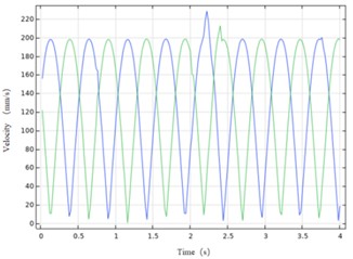
Fig. 14Curve of deformation 0.6 flexible ring and velocity
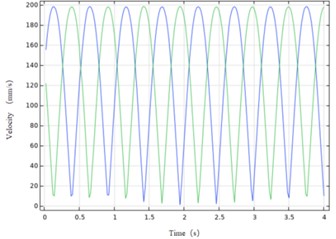
Fig. 15Curve of deformation 0.7 flexible ring and velocity
4. Conclusions
1) Stress Distribution Law: the simulation analysis shows that the maximum stress concentration of the flexible ring appears in the contact area with the inner and outer conductive rings. The maximum bending stress increases sharply from 93.5 MPa to 217 MPa when the deformation increases from 0.3 mm to 0.7 mm.
2) The change of motion stability: with the increase of the deformation of the flexible ring, its motion state tends to be stable. The specific performance is that the periodic oscillation of the velocity curve of the probe point is weakened, and the waveform tends to be smooth, which indicates that the overall motion stability of the power rolling ring has been gradually improved.
3) Comprehensive effect conclusion: the study reveals that increasing the deformation of the flexible ring will have a dual effect: on the one hand, it will help to improve the motion stability of the rolling ring, but on the other hand, it will also lead to a significant increase in the stress in the contact area, both of them need to be optimized in the design.
References
-
E. Hong, A. Krishnamurthy, D. A. Gregory, and S. Anderson, “Optical slip ring for sensor interface applications,” in Proceedings, Vol. 6222, p. 62220E, 2006, https://doi.org/10.1117/12.667667
-
X. Feng, Z. Fu, B. Wei, and Y. Weng, “Multi-channel signal transmission method of non-contact slip ring based on capacitive coupling and quasi-time division multiplexing,” Review of Scientific Instruments, Vol. 90, No. 4, Apr. 2019, https://doi.org/10.1063/1.5089226
-
J. Chen, M. Rong, F. Yang, Y. Wu, H. Sun, and Y. Yang, “Numerical research on the electrical contact model and thermal analysis of the Roll-Ring,” in 2nd International Conference on Electric Power – Switching Technology (ICEPE-ST), pp. 1–4, 2013, https://doi.org/10.1109/icepe-st.2013.6804345
-
J. Chen, F. Yang, K. Luo, Y. Wu, and M. Rong, “Experimental investigation of the electrical contact characteristics in Rolling Contact Connector,” in IEEE 61st Holm Conference on Electrical Contacts (Holm), pp. 235–240, Oct. 2015, https://doi.org/10.1109/holm.2015.7355103
-
P. E. Jacbson, “Rotating electrical transfer components,” US, US:6767217B2.2002-03-12, Mar. 2002.
-
T. M. Myrick, “Roll-Ring conductive wheel,” US, US:7215045B1.2004-10-15, Oct. 2004.
-
M. Howard, “Alternating cage coupler,” US, US:7946851B2.2009-05-29, May 2009.
-
“Roll-Ring® technology,” Diamond-Roltran, LLC, 2008.
About this article

The authors would like to thank the Science and technology development plan project of Jilin province No. YDZJ202401326ZYTS and the Gan-Po Talent Support Program of Jiangxi Province No. 20243BCE51035.
The datasets generated during and/or analyzed during the current study are available from the corresponding author on reasonable request.
The authors declare that they have no conflict of interest.

