Abstract
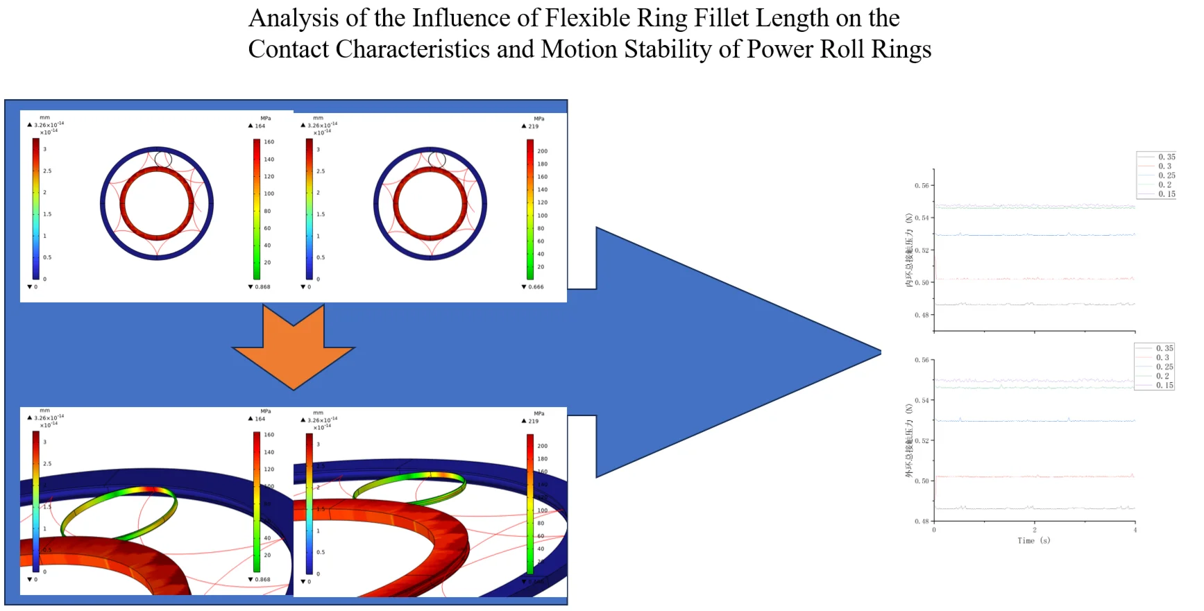
Based on the COMSOL Multiphysics simulation platform, this paper establishes a complete finite element model of a power roll ring assembly. The model consists of inner and outer conductive rings made of H62 brass and a flexible ring made of C17200 beryllium bronze. After meshing, a rotational speed was applied to the inner conductive ring according to actual working conditions, and consistent boundary conditions and friction coefficients were set at the contact pairs for transient dynamic analysis. The study focuses on investigating the influence of the flexible ring’s fillet length (0.15 mm, 0.20 mm, 0.25 mm, 0.30 mm, 0.35 mm) on the system’s contact characteristics and motion stability. By analyzing stress nephograms, motion trajectory diagrams, and quantitatively calculating contact pressure, the results show that the maximum contact stress of the flexible ring is concentrated at the contact points with the inner and outer conductive rings and increases with the fillet length. However, the contact pressure decreases as the fillet length increases, with small fluctuation amplitude, ensuring the operational stability of the power roll ring. This research provides a theoretical basis and an effective method for the structural optimization and performance evaluation of power roll rings.
Highlights
- The maximum contact stress of the flexible ring concentrates at contact points with inner/outer conductive rings. It increases with the flexible ring's fillet length/radius, reflecting a trade-off between assembly convenience and contact stress.
- As fillet length increases, the contact pressure between the flexible ring and inner/outer conductive rings decreases, with small fluctuation amplitude, effectively ensuring the power roll ring's operational stability and contact reliability.
- Fillet size involves a trade-off—small fillets reduce contact stress but increase contact pressure, and vice versa. Optimal design requires balancing fillet radius within an intermediate range based on material limits and service life, providing critical basis for structural optimization.
1. Introduction
Power roll rings (also known as conductive slip rings) are key rotating connection devices for transmitting energy and signals, widely used in precision equipment requiring unlimited rotation, such as spacecraft, wind turbine generators, and radar systems [1, 2]. Their core function is to establish a stable electrical connection between fixed and rotating components. Their performance and reliability directly determine the operational lifespan and stability of the entire system [3, 4].
The typical structure of a power roll ring includes a fixed outer conductive ring, a rotating inner conductive ring, and a flexible ring situated between them that functions as both a conductor and a force transmission element [5, 6]. During operation, the high-speed rotation of the inner conductive ring drives the motion of the flexible ring through friction, forming a complex multibody dynamic contact problem. As the core load-bearing and conductive component, the contact state (including contact stress, rolling-sliding characteristics, and motion stability) between the flexible ring and the inner/outer conductive rings is a critical factor affecting contact resistance, frictional temperature rise, wear life, and even overall system failure [7, 8]. Therefore, precise multibody dynamic simulation analysis of power roll rings and in-depth investigation of their dynamic contact mechanisms are of great significance for optimizing design and improving reliability.
Current research on roll rings mostly focuses on material selection, electrical performance, or macroscopic friction and wear experiments. There is a lack of in-depth quantitative analysis of their internal dynamic contact behavior, particularly regarding the influence law of the flexible ring's structural parameters on the system's dynamic characteristics. The fillet length of the flexible ring, as a key structural parameter, directly affects its flexibility and contact area, thereby altering the stress distribution, motion mode, and velocity relations in the contact region [9]. However, there is no clear conclusion on how the fillet length systematically affects core dynamic parameters such as the slip-roll ratio and contact pressure of the flexible ring.
To address the aforementioned issues, this paper, based on multibody dynamics theory and utilizing the finite element analysis software COMSOL Multiphysics, establishes a refined simulation model of a power roll ring. It focuses on studying the variation patterns of stress distribution, motion trajectory, velocity field, slip-roll ratio, and contact pressure of the flexible ring under different fillet lengths (0.15 mm, 0.2 mm, 0.25 mm, 0.3 mm, 0.35 mm). This study aims to reveal the intrinsic relationship between the structural parameters of the flexible ring and the system's dynamic performance, providing a theoretical basis and data support for the structural design and performance optimization of power roll rings.
2. Influence of fillet length on stress
After establishing the overall simulation model of the power roll ring and performing meshing, H62 brass material was assigned to both the outer and inner conductive rings, and C17200 beryllium bronze material was assigned to the flexible ring according to the actual situation, finally forming the assembly of the signal slip ring. A certain rotational speed was set on the inner conductive ring, consistent boundary pairs were added at the contacts, and a friction coefficient was assigned. Transient analysis was performed on the entire model, yielding the following results.
Fig. 1Motion trajectory of inverted arc 0.15 power rolling ring
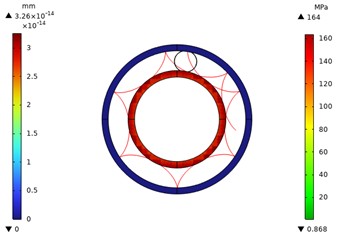
Fig. 2Stress distribution map of a 0.15 power rolled bead on an inverted arc
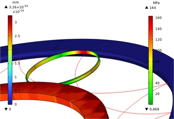
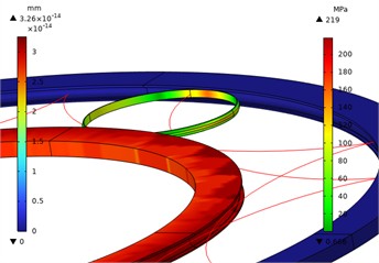
Figs. 1-10 show the overall and local stress and displacement contour plots for the power roller ring. The inner and outer conductive rings display displacement contour plots, while the flexible ring shows stress contour plots. The figures reveal that the maximum stress on the flexible ring occurs at its contact points with the inner and outer conductive rings. This maximum stress increases as the radius of the flexible ring's fillet curve grows. The red line represents the motion trajectory of a specific point on the flexible ring, indicating that the overall structural movement is reasonable.
Fig. 3Motion trajectory diagram of 0.2 power roller ring with inverted arc
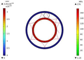
Fig. 4Local stress contour diagram of 0.2 power roller ring with wide inverted arc
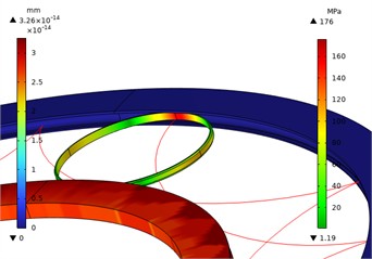
Fig. 5Motion trajectory diagram of 0.25 power roller ring for inverted arc
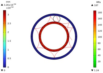
Fig. 6Local stress contour diagram of 0.25 power roller ring for inverted arc
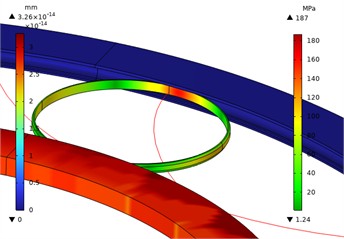
Fig. 7Motion trajectory diagram of 0.3 power roller ring with inverted arc
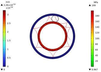
Fig. 8Local stress contour diagram of 0.3 power roller ring with inverted arc
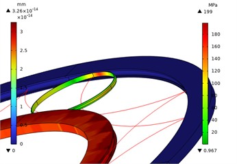
Fig. 9Motion trajectory diagram of 0.35 power roller ring with inverted arc
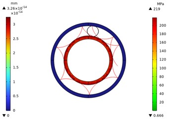
Fig. 10Local stress contour diagram of 0.35 power roller ring with inverted arc
2.1. Flexible ring contact condition setup
To further analyze contact pressure variations between the signal roll ring’s flexible ring, outer conductive ring, and inner conductive ring, the contact pressure changes for each component were calculated via surface integration of derived values in the COMSOL simulation results. The total pressure was then computed from these component values. First, define the surface as the flexible ring contact surface in the dataset. Next, configure the filter by entering “mbd.Tn” in the expression field, with units set to N/m2. Select the lower bound in the boundary settings and set its value to 0.001. This establishes a criterion for determining whether the flexible ring will make contact with the inner or outer conductive rings.
2.2. Calculation of flexible ring contact pressure
The radius of the inner conductive ring is , and the radius of the flexible ring is . The distance from the center of the inner conductive ring to the center of the flexible ring is . For convenience in calculation and determination, this value is set to 52 mm. Perform surface integration on the derived values. Select the filter for the dataset. The contact pressure determination formula for each component is mbd.Tn*(> 52 [mm]). The “Tn” followed by “” denotes the contact pressure component in a specific direction. The expression “” defines the required evaluation range. Since the flexible ring only exerts contact pressure on the inner and outer conductive rings, when the distance is less than 52 mm, the integrated area corresponds to the portion in contact with the inner conductive ring. Conversely, when the distance exceeds 52 mm, the integrated area corresponds to the portion in contact with the outer conductive ring. This allows differentiation between the contact regions of the inner and outer conductive rings. Finally, the contact pressure is calculated using the formula.
Fig. 11Contact pressure curve diagram of flexible ring with inner and outer conductive rings
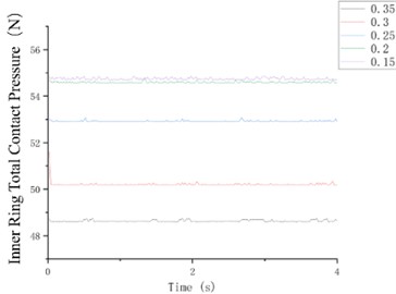
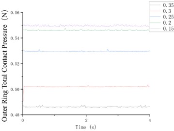
Fig. 11 show the contact pressure curves between the flexible ring and the inner/outer conductive rings at different fillet lengths. The figures reveal that as the fillet length increases, the contact pressure decreases to a more reasonable value. The contact pressure exhibits minimal variation, with overall fluctuations remaining small, thereby ensuring stable operation of the power roll ring.
3. Conclusions
Through transient dynamic simulations of power rollers with varying fillet radii, this study draws the following key conclusions:
1) Simulated motion trajectories of the flexible rings are realistic, confirming the overall model’s accuracy, including its geometry, mesh, and boundary conditions.
2) Stress concentrates at the flexible ring’s contact points with the inner and outer conductive rings. A key finding is that a larger fillet radius increases the maximum contact stress, indicating a trade-off between easing assembly and exacerbating contact stress.
3) A larger fillet radius effectively reduces the contact pressure between the rings. Furthermore, minimal pressure fluctuation across different fillet sizes demonstrates the power roll ring’s operational stability and contact reliability.
4) Fillet size presents a design trade-off: a smaller radius decreases contact stress but increases contact pressure, and vice versa. For optimal performance, the fillet radius should be balanced within an intermediate range, based on material limits and lifespan requirements.
References
-
Y. Zhou, C. Zhu, H. Liu, H. Bai, and X. Xu, “Investigation on stress microcycles and mild wear mechanism in gear contact fatigue,” Fatigue and Fracture of Engineering Materials and Structures, Vol. 44, No. 9, pp. 2265–2279, May 2021, https://doi.org/10.1111/ffe.13486
-
J. W. Seo, H. K. Jun, and S. J. Kwon, “Rolling contact fatigue and wear of two different rail steels under rolling-sliding contact,” International journal of fatigue, Vol. 83, pp. 184–194, 2016.
-
B. C. Stump, Y. Zhou, M. B. Viola, H. Xu, R. J. Parten, and J. Qu, “A rolling-sliding bench test for investigating rear axle lubrication,” Tribology International, Vol. 121, pp. 450–459, May 2018, https://doi.org/10.1016/j.triboint.2018.01.058
-
T. Chen et al., “Current-carrying contact character and wear behavior of an elastic ring at different rolling speeds,” Engineering Failure Analysis, Vol. 131, p. 105825, Jan. 2022, https://doi.org/10.1016/j.engfailanal.2021.105825
-
P. E. Jacobson, “Muti-Hundred Kilowatt Roll Ring Assembly Final Report.US NASA report NO.CR-174832,” NASA, Apr. 1985.
-
J. Chen, M. Rong, F. Yang, Y. Wu, H. Sun, and Y. Yang, “Numerical research on the electrical contact model and thermal analysis of the Roll-Ring,” in 2nd International Conference on Electric Power Equipment – Switching Technology (ICEPE-ST), pp. 1–4, Oct. 2013, https://doi.org/10.1109/icepe-st.2013.6804345
-
J. Zhang, H. Shi, and Z. Dong, “Real-time remaining useful life prediction based on adaptive kernel window width density,” Measurement Science and Technology, Vol. 33, No. 10, p. 105122, Oct. 2022, https://doi.org/10.1088/1361-6501/ac7a91
-
K. He, Z. Su, X. Tian, H. Yu, and M. Luo, “RUL prediction of wind turbine gearbox bearings based on self-calibration temporal convolutional network,” IEEE Transactions on Instrumentation and Measurement, Vol. 71, pp. 1–12, Jan. 2022, https://doi.org/10.1109/tim.2022.3143881
-
J. Zhu, N. Chen, and W. Peng, “Estimation of bearing remaining useful life based on multiscale convolutional neural network,” IEEE Transactions on Industrial Electronics, Vol. 66, No. 4, pp. 3208–3216, Apr. 2019, https://doi.org/10.1109/tie.2018.2844856
About this article

The authors would like to thank the Science and technology development plan project of Jilin province No. YDZJ202401326ZYTS and the Gan-Po Talent Support Program of Jiangxi Province No. 20243BCE51035.
The datasets generated during and/or analyzed during the current study are available from the corresponding author on reasonable request.
The authors declare that they have no conflict of interest.
