Abstract
The linear rolling guideway, in which exit a lot of rolling interfaces between the rolling balls and the grooves and exhibit complex mechanical behaviors under the static and dynamic loads on supporting direction, will directly affect the machining accuracy and efficiency of CNC machine tool. In the paper, the precise finite element modeling and analysis approach were studied for the dynamics on supporting direction of linear rolling guideway. Firstly, the contact characteristic between a single ball and grooves was analyzed, and the relative contact stiffness was determined under the different preload levels. Moreover, on the basis of considering the guideway structure and rolling ball distribution, the precise finite element model was created and the correctness of modeling method was verified by comparison with the analytic results. At last, the obtained precise modeling method of the linear rolling guideway was applied to the dynamics analysis of a working table of CNC machine tool and the rationality of analysis was explained by comparing with the experiment.
1. Introduction
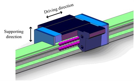
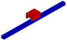
The linear rolling guideway is a complex assembly system consisted of rail, carriage, cage, rolling ball, etc. As a key functional component, the dynamics of linear rolling guideway directly affects the machining accuracy and efficiency of CNC machine tool, which has become an important part of the CNC machine tool design [1-3]. In a CNC machine tool, the functions of linear rolling guideway are supporting and transportation of spindle box, worktable or other structures, therefore, contrasted with which the dynamic characteristics can also be divided into the supporting direction and movement direction as shown in Fig. 1. For the guideway dynamics on movement direction, the contact frictional behavior between the rolling balls and the grooves must be considered and complex modeling will be done using the nonlinear dynamics theory. The analysis results can be applied in the position control of CNC machine tools directly which provides great significance. At present, some researchers [4-6] have got some achievements on studying the dynamics of guideway on movement direction. However, the research of guideway dynamics on movement direction is still at exploratory stage and a great gap exits between the research and solving practical engineering problems because the mechanisms of friction and damping of guideway system are not clear.
A lot of rolling interfaces exit between the rolling balls and the grooves in linear rolling guideway, and the complex mechanical behaviors will take place under the static or dynamic loads on supporting direction, which will affect the nature characteristics and dynamics responses of CNC machine tools. Therefore, it is also important to research the dynamics of guideway system on supporting direction. This paper provides the dynamic modeling and analysis method on supporting direction of guideway system. More achievements about the dynamics of guideway system on supporting direction have been made comparing with the movement direction dynamics. For example, Dhupia [7] provided a very simple and macro modeling method to analyze the dynamics of guideway by simplifying the elastic contacts of rolling interfaces with four vertical springs and four horizontal springs. Ohta [8-9] conducted a vibration analysis and obtained nature frequencies of the linear guide mechanism using analytical method considering the contact between each ball and grooves as spring element. To avoid the complexity in mesh generation of the rolling grooves in the finite element model, Hung [10-11] simplified the four rolling grooves to two, but with equivalent contact stiffness at the rolling interface as that of the original guideway model. The above-mentioned researches have contributed to the understanding of the mechanical characteristics and creating the effective dynamics models of guideway system on supporting direction substantially. However, these researches are all based on some necessary assumptions, such as, the spring element could simulate the contact behaviors between rolling ball and grooves, the two rolling grooves could express the dynamics of actual four rolling grooves, and so on. These assumptions will affect the analysis accuracy under inappropriate application.
Fig. 1The supporting direction and movement direction of linear rolling guideway
In the real guideway system, there are 3D surface-to-surface contacts between rolling balls and grooves, so some researchers used the surface-to-surface contact models to analyze the supporting direction dynamics. For example, Dadalau [12] adopted surface-to-surface contact elements to simulate the actual contact behaviors and solved the statics of guideway system. Chang [13] employed a contact element of zero thickness to create the model of rolling interface and predict the vibration characteristics of a rolling guideway. The large amount of calculation will be consumed if using the 3D surface-to-surface contact elements to analyze the mechanical properties of guideway system. In the opinion of the author, the 3D surface-to-surface contact elements are only effective to analyze the statics properties of the guideway system and not suitable to solve the dynamics due to the lower compute efficiency. But the statics calculation using the 3D surface-to-surface contact elements is able to accurately obtain the spring element stiffness parameters which are required for dynamics analysis.
Therefore, on the basis of utilizing the results of contact analysis and considering the structure, a modeling technique of guideway system was developed on the supporting direction, which could precisely obtain the dynamic characteristics with no or less experiment data. In section 2, the contact characteristic between a single ball and groove was analyzed using the contact element, and a method of obtaining the contact stiffness was proposed with the data provided by guideway manual. In section 3, on the base of fully considering the guideway structure and rolling ball distribution, the precise finite element model was created which was verified by the analytic results. In section 4, the obtained precise modeling method of linear rolling guideway was applied to the dynamics analysis of a working table of CNC machine tool and the rationality of analysis was explained by comparing with the experiment.
2. Finite element modeling of contact between a single ball and grooves
The contact stiffness between each ball and grooves is a key parameter to create the dynamics model of guideway system on supporting direction. The contact stiffness of rolling interface could be obtained from the 3D surface-to-surface contact model accurately. The finite element modeling of contact between a single ball and grooves will be introduced in this section.
2.1. Modeling method
The contact between ball and grooves is a kind of nonlinear mechanical behavior, which could be simulated with ANSYS software. The rolling ball SHS-35R guideway produced by THK Corporation was taken to explain the contact modeling method with ANSYS as an example. Two mass blocks are chosen to simulate the contact between rolling ball and rail or carriage, and the basic parameters required in the contact modeling are listed in Table 1.
Table 1Parameters of the rolling ball and grooves
Components | Values of parameters |
The upper mass block (length×width×height) (mm) | 4×10×6 |
The lower mass block (length×width×height) (mm) | 4×10×6 |
The diameter of rolling ball (mm) | 6.35 |
The radius of grooves (mm) | 3.302 |
Young’s modulus of components (GPa) | 206 |
Poisson’s ratio of components | 0.3 |
The created finite element model of contact between rolling ball and grooves is shown in Fig. 2. The rolling ball and grooves are modeled with Solid92 element, and the contacts between rolling ball and grooves are modeled with Conta174 contact element and Targe170 target element, respectively. As a whole, the model consists of 76579 elements and 103108 nodes, in which the amount of contact elements and target elements are 4796 and 316, respectively. To exclude the impact of mesh density on the results, the meshes of contact areas are refined.
Fig. 2The contact finite element model of the rolling ball and grooves
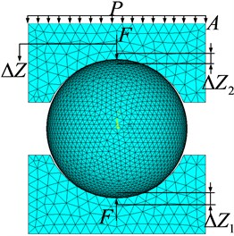
The initial contact stiffness factor should be set in ANSYS, which is determined as 0.8 through stiffness test. The degrees of freedom on non-contact direction are constrained and the uniform load is applied on the surface of upper mass block, which simulates the different preloads on the rolling ball, where is preload of guideway and is the area of active surface. The total deformation can be solved by contact analysis module of ANSYS, then the contact stiffness between rolling ball and grooves could be gotten according to Eq. (1) to Eq. (3):
where is the total deformation between rolling ball and grooves with preload, is the deformation between rolling ball and groove of rail, is the deformation between rolling ball and groove of carriage, is the contact stiffness between rolling ball and groove of rail, is the contact stiffness between rolling ball and groove of carriage. Corresponding to different preloads of guideway, the uniform loads can be adjusted, so the model is suitable to calculate the contact stiffness of different preloads of guideway.
The contact stiffness between rolling ball and grooves also could be calculated by Hertzian contact theory, the formulas [14] are:
where represents the relationship between preload and total deformation , called resemble stiffness coefficient. The rationality of finite element modeling method could be verified by the results of Hertzian contact formulas.
2.2. Determination of contact stiffness between rolling ball and grooves
The preload of guideway has significant influence on contact stiffness between rolling ball and grooves. In this section, the contact stiffness under different preload will be calculated by the created finite element model and Hertzian contact formulas.
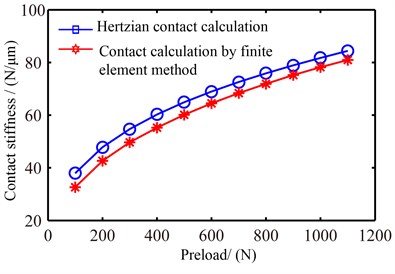
The effects of preload on contact deformation and contact stiffness between rolling ball and grooves are shown in Fig. 3 and Fig. 4 respectively. Both the contact deformation and contact stiffness increase with the increment of preloads, which are not linear tendency, and the both growth rates gradually decrease. However, the contact deformation and stiffness obtained with finite element method is slight difference with the analytical results, but the tendencies of variation are consistent, which could indicate the contact calculation with the created finite element model is correct.
The rail and carriage are usually assumed as rigid bodies in Hertzian contact analysis, and only the rolling balls are taken as elastic bodies. These assumptions will introduce the errors for the contact stiffness calculation. However, the various factors which impact the calculation results of contact stiffness are considered in the contact finite element modeling, so the calculation of finite element method should be more accurate than the analytical method. Therefore, the results from finite element method are adopted to predict the contact stiffness between rolling ball and grooves. According to Fig. 4, the values of contact stiffness between rolling ball and grooves can be determined by given preload, which is useful for the dynamics model of the linear rolling guideway on supporting direction.
Fig. 3Contact deformation at different preloads
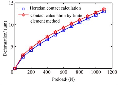
Fig. 4Contact stiffness at different preloads
3. Precise finite element modeling of dynamics on the supporting direction
To achieve the precise finite element modeling, the following three key steps, determining the contact stiffness between rolling ball and grooves, using the spring-mass elements to simulate the dynamics behaviors between rolling ball and grooves, creating the dynamics model on supporting direction, should be carried out.
The first step has been introduced in section 2 in detail. The obtained value of contact stiffness is a key parameter for the modeling of step 2. For the dynamics analysis of guideway system, using the spring element to simulate the contact between rolling ball and grooves is the most frequently used method and has been widely accepted. Here, the spring element is corrected by spring-mass element, and the mass of rolling ball is considered in the new element as shown in Fig. 5. Where is the mass of rolling ball, is the equivalent stiffness between rolling ball and grooves, and are the equivalent stiffness between rolling ball and rail or carriage respectively, meanwhile, , , is contact angle. It is clear that the created dynamic model is superior to the classical spring element model, and is easier to introduce the value of contact stiffness obtained by contact finite element analysis in section 2.
Fig. 5Dynamics modeling for the contact between rolling ball and grooves
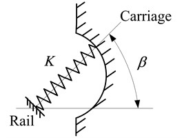
a) The spring element
b) The spring-mass element
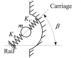
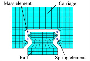
After finishing the dynamics modeling between a single rolling ball and grooves, the dynamics model on supporting direction can be created for the linear rolling guideway. The guideway system with four rolling grooves is taken as study case to explain the dynamic modeling method. As shown in the Fig. 6, considering the distribution of rolling balls in each groove, the spring-mass elements are adopted to connect the carriage and rail, and the angle of spring is . The carriage and rail are simulated by solid elements. Then, the whole dynamics model on supporting direction is achieved. Because of considering the distribution of rolling balls, the created dynamics model on supporting direction is closer to the real guideway structure and has a higher accuracy.
Fig. 6The whole finite element model of the linear rolling guideway
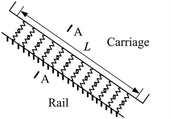
a) Lateral view
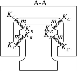
b) Cross-section
The analytical model of the whole guideway system could also be done with Lagrange equation, and the formulas of solving nature frequencies [15] for the above guideway system are:
where , , , , are the nature frequencies of the vertical, pitching, yawing, the low-order rolling and the high-order rolling modal movement respectively, is the length of load area of rolling ball, , , are the rotation inertia of carriage around the , , axis, is the mass of carriage, , , are the corresponding coefficients related with geometries of guideway and contact stiffness between rolling ball and grooves.
By comparing the analytical modeling with Lagrange equation and the proposed modeling method, the reasonability of precise finite element modeling can be verified.
4. Study case
In this section, the precise finite element modeling method of guideway system will be demonstrated using the SHS-35R guideway. The nature characteristics of the guideway will be solved by the proposed method and analytical method.
4.1. Dynamic modeling of guideway on supporting direction
From the guideway manual provided by THK Corporation, the relative parameters used for modeling can be determined and listed in Table 2. According to the provided preload levels, the contact stiffness between rolling ball and grooves can be acquired from the Fig. 3. The contact stiffness is determined as 54.70 N/μm for low preload and 79.32 N/μm for middle preload.
Table 2Parameters of the linear rolling guideway
Item | Values of parameters |
The mass of carriage, | 1.811 kg |
The rotation inertia of carriage around the , | 1.2085×10⁻³ kg m2 |
The rotation inertia of carriage around the , | 1.6014×10⁻³ kg m2 |
The rotation inertia of carriage around the , | 2.2176×10⁻³ kg m2 |
The length of load area of rolling ball, | 93×10-3 m |
Contact angle, | 45° |
Low preload | 390 N |
Middle preload | 1040 N |
The average number of ball in each rolling groove, | 12 |
Then, the dynamic model of guideway on supporting direction could be created with the proposed method in section 3 and shown in Fig. 7. In the model, each rolling ball is modeled by COMBIN14 spring element and MASS21 mass element, and the rail and carriage are modeled by Solid45 element. As a whole, there are 13136 nodes, 96 spring elements, 48 mass elements and 10239 solid elements applied in this model.
Fig. 7Finite element model of a linear rolling guideway with spring-mass elements
It should be noted that, the end caps at both ends of carriage and the retainer between rolling balls are ignored in the dynamics model. Because the masses of end cap and retainer are very small compared with the main mass, such as rail, carriage and rolling ball, this assumption will not take significant impact on the dynamics of the whole guideway system.
4.2. Solving the nature characteristics of guideway
Modal analysis of the guideway with low and middle preload are done respectively by ANSYS software. The first 5-orders nature frequencies are listed in Table 3 and Table 4, in which also include the results got with analytical formulas. Both the finite element and the analytical results reveal that the natural frequencies of a linear guideway increase with the increment of the preload. The reason is that the contact stiffness for the middle preload guideway is greater than the one of low preload guideway. But the modal shapes for the two preload statuses are consistent. The first 5-orders modal shape are corresponding to five kinds of modal movement, such as low-order rolling, yawing, pitching, vertical and high-order rolling shown in Fig. 8.
The differences of calculation results between finite element method and analytical method are also listed in the Table 3 and Table 4. From the comparison of the two kinds of methods, the conclusion can be drawn that the precise finite element modeling method proposed in this study is correct.
Table 3The obtained nature frequencies for the low preload guideway
Order | Finite element method /Hz | Analytical method /Hz | Difference |
1 | 1308.5 | 1421.5 | 7.95 |
2 | 2105.6 | 2316.6 | 9.11 |
3 | 2681.1 | 2726.0 | 1.65 |
4 | 2925.2 | 3030.0 | 3.46 |
5 | 4022.8 | 3792.0 | 6.09 |
Table 4The obtained nature frequencies for the middle preload guideway
Order | Finite element method A/Hz | Analytical method B/Hz | Difference |
1 | 1499.2 | 1711.8 | 12.42 |
2 | 2444.8 | 2789.6 | 12.36 |
3 | 3110.6 | 3282.6 | 5.24 |
4 | 3409.2 | 3648.7 | 6.56 |
5 | 4718.8 | 4566.3 | 3.34 |
Fig. 8The first 5-orders mode shapes of guideway system
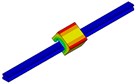
a) Low-order rolling
b) Yawing
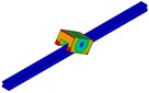
c) Pitching
d) Vertical
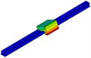
e) High-order rolling
5. Application of the proposed modeling method
The dynamic modeling method on supporting direction of guideway could be applied to the modeling and analysis of whole CNC machine tool or part system. In this section, a working table of CNC machine tool will be modeled and analyzed with the proposed method. The real structure of working table was shown in Fig. 9(a), which was supported by two SHS-35R guideways produced by THK Corporation and lightly preloaded. To simplify the analysis, the ball screw was removed, and then the contribution of the dynamics characteristics on supporting direction of guideway was only considered for the dynamics of working table.
Fig. 9A working table of CNC machine tool
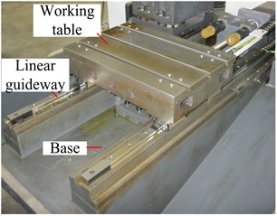
a) Real structure of working table
b) Wireframe model of working table used to test
5.1. Testing nature frequencies of working table
Dynamic ping testing is adopted to obtain the nature frequencies of working table with B&K system and the wireframe model of working table used to modal test is shown in Fig. 9(b). The node 7 is taped with a modal hammer respectively from vertical and horizontal direction and a 3D acceleration sensor located in node 6 is used to pick up the vibration response. From the obtained exciting and response signals, the frequency response function can be produced, which is used to identify the nature frequencies. Fig. 10 shows the frequency response curve corresponding to vertical tap by the hammer. Peak amplitudes on the curve indicate nature frequencies. It can be seen from Fig. 10, no matter which frequency response curve is chosen to identify the nature frequencies of working table, the results are identical. The obtained nature frequencies are listed in Table 5. Because it is very difficult to measure the response of below node of working table, the mode shapes of working table were not measured in this study.
Fig. 10The obtained frequency response curves
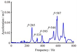
a) Frequency response curve of direction
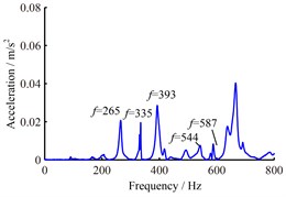
b) Frequency response curve of direction
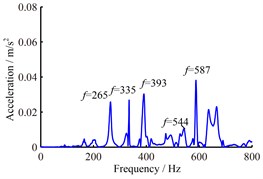
c) Frequency response curve of direction
Table 5The obtained nature frequencies by experiment and dynamics analysis/Hz
Order | Experiment | Precise finite element method | Engineering method | Difference |
1 | 265 | 238.50 | 930.40 | 10.0 % |
2 | 335 | 367.86 | 1202.1 | 9.81 % |
3 | 393 | 403.87 | 1303.7 | 2.77 % |
4 | 544 | 450.43 | 1446.2 | 17.2 % |
5 | 587 | 618.50 | 1519.1 | 5.37 % |
5.2. Calculating nature frequencies of working table
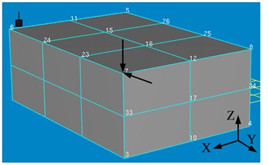
Fig. 11(a) shows the finite element model of working table which includes the precise finite element model of guideway. For the created model, SOLID45 element is used to simulate working table and base, COMBIN14 spring element and MASS21 mass element are chosen to simulate the contact between rolling ball and grooves. As a whole, there are 46323 elements and 60995 nodes in the model. Under low preload status, the contact stiffness has been determined as 54.70 N/μm. Then, the nature frequencies of working table can be calculated and the results are also listed in Table 5.
In some engineering analysis, the rail and carriage are usually regarded as rigid connection, that is, the interfaces effect of guideway on dynamics is ignored. The finite element model is created with this kind of engineering modeling method shown in Fig. 11(b). There are 104146 SOLID45 elements and 24709 nodes in the model. The nature frequencies are also calculated and listed in Table 5.
Fig. 11The finite element model of working table
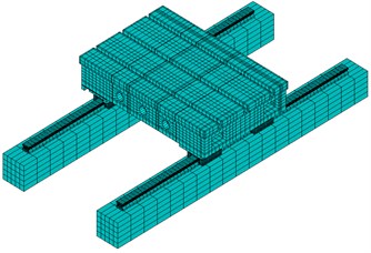
a) The finite element model created by precise finite element modeling method
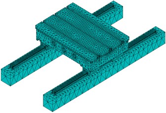
b) The finite element model created by engineering method
The results obtained from experiment, precise finite element method and engineering method are compared in Table 5. It can be seen that there are large difference between experiment and engineering method for the obtained nature frequency values. But the nature frequency values obtained by precise finite element method and experiment are basically coincident, and the maximum difference is less than 10 %. Therefore, during the dynamics modeling of whole CNC machine tool or part system, the contribution of guideway joint must be considered.
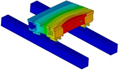
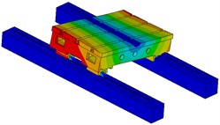
Furthermore, the precise finite element method is applied to solve the modal shapes of working table and the results are shown in Fig. 12. The 5-order modal shapes of working table display as yawing, low-order rolling, low-order pitching, high-order pitching and high-order rolling movement.
Fig. 12The 5-order modal shapes of working table
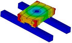
a) The first order
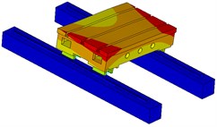
b) The second order
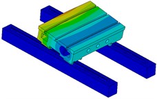
c) The third order
d) The fourth order
e) The fifth order
The reason of producing these modal shapes is due to the modal movement of carriage of guideway. Because there are 4 carriages in the system, different modal movement forms appear for the working table. It further illustrates that the dynamics of guideway have a significant impact on the dynamics of working table.
6. Conclusions
To calculate the dynamics characteristics on supporting direction of guideway, a precise finite element method was proposed in this study. A contact finite element model was created, which describes the contact characteristic between a single ball and grooves. Using the model, the contact stiffness between rolling ball and grooves can be determined under the different preload status. The procedure of creating the precise finite element model of guideway was proposed, which include 3 key steps, such as determining the contact stiffness between rolling ball and grooves, using the spring-mass elements to simulate the dynamics behaviors between rolling ball and grooves, creating the dynamics model on supporting direction. The precise finite element modeling method of guideway system was demonstrated using the SHS-35R guideway produced by THK Corporation. The nature characteristics of the guideway were solved by the proposed method and analytical method. The results of two kinds of methods were found to be consistent, and then the correctness of the proposed method was verified. The obtained precise modeling method of the linear rolling guideway was also applied to the dynamics analysis of a working table of CNC machine tool and the rationality of analysis was explained by comparing with the experiment results. This study shows that the contribution of guideway joint must be considered during the dynamics modeling of whole CNC machine tool or part system.
References
-
Huang Y. M., Fu W. P., Dong L. X., et al. Research on the normal dynamic characteristic parameters of joint surface. Journal of Mechanical Engineering, Vol. 29, Issue 3, 1993, p. 74-77.
-
Lin Y., Chen W. A method of identifying interface characteristic for machine tools design. Journal of Sound and Vibration, Vol. 255, Issue 3, 2002, p. 481-487.
-
Lin C. Y., Hung J. P., Lo T. L. Effect of preload of linear guides on dynamic characteristics of a vertical column–spindle system. International Journal of Machine Tools & Manufacture, Vol. 50, Issue 8, 2010, p. 741-746.
-
Al-Bender F., Symens W. Characterization of frictional hysteresis in ball-bearing guideways. Wear, Vol. 258, Issue 11, 2005, p. 1630-1642.
-
Lu L., Yao B., Wang Q., et al. Adaptive robust control of linear motors with dynamic friction compensation using modified LuGre model. Automatica, Vol. 45, Issue 12, 2009, p. 2890-2896.
-
Symens W., Al-Bender F. Dynamic characterization of hysteresis elements in mechanical systems, Part II: Experimental validation. Chaos, An Interdisciplinary Journal of Nonlinear Science, Vol. 15, Issue 1, 2005, p. 013106-013106-9.
-
Dhupia J. S., Ulsoy A. G., Katz R., et al. Experimental identification of the nonlinear parameters of an industrial translational guide for machine performance evaluation. Journal of Vibration and Control, Vol. 14, Issue 5, 2008, p. 645-668.
-
Ohta H. Sound of linear guideway type recirculating linear ball bearings. Journal of Tribology, Vol. 121, Issue 4, 1999, p. 678-685.
-
Ohta H., Hayashi E. Vibration of linear guideway type recirculating linear ball bearings. Journal of Sound and Vibration, Vol. 235, Issue 5, 2000, p. 847-861.
-
Hung J. P. Load effect on the vibration characteristics of a stage with rolling guides. Journal of Mechanical Science and Technology, Vol. 23, Issue 1, 2009, p. 92-102.
-
Hung J. P., Lai Y. L., Lin C. Y., et al. Modeling the machining stability of a vertical milling machine under the influence of the preloaded linear guide. International Journal of Machine Tools & Manufacture, Vol. 51, Issue 9, 2011, p. 731-739.
-
Dadalau A., Groh K., Reu M., et al. Modeling linear guide systems with CoFEM: equivalent models for rolling contact. Production Engineering, Vol. 6, Issue 1, 2012, p. 39-46.
-
Chang J. C., Wu J. S. S., Hung J. P. Characterization of the dynamic behavior of a linear guideway mechanism. Structural Engineering and Mechanics, Vol. 25, Issue 1, 2007, p. 1-20.
-
Wu J. S. S., Chang J. C., Hung J. P. The effect of contact interface on dynamic characteristics of composite structures. Mathematics and Computers in Simulation, Vol. 74, Issue 6, 2007, p. 454-467.
-
Sun W., Wang B., Lu M., et al. Analytical modeling of linear rolling guide system based on Lagrange equation. Computer Integrated Manufacturing Systems, Vol. 18, Issue 4, 2012, p. 781-786.
About this article

This study was supported by the National Natural Science Foundation of China, 50905029.
