Abstract
This study is concerned with the vibration transmission between two subsystems of a vehicle: the chassis which is considered as an elastic structure and the powertrain which is considered as a rigid body. The study is carried out based on a new coupling matrix constructed from equations of dynamic behavior of each subsystems. This matrix depends only on the impedance matrices of the two subsystems and the mechanical characteristics of the linking mounts. Under some assumptions, a simplified expression to obtain the overall behaviour of the entire system is proposed. Despite its sensitivity to the degree of coupling between the subsystems, this method can be applied to the case of sub-structures with weak coupling. The results obtained from a simple example and from a more complex industrial structure representing a city bus are presented.
1. Introduction
The design of vehicle powertrain and its mounting system is essential for improving the vehicular characteristics for noise and vibration. The powertrain vibration isolation from the rest of the vehicle is a problem often encountered in the design stage in the automotive field. Several methods have been developed to minimize the interactions between the powertrain and chassis. Most of these methods, which focus on the positioning and the design of resilient supports are based on decoupling rigid body modes from a grounded powertrain model with constant properties [2, 3, 4, 5, 8] or with characteristics that depend on the frequency or deflection [12, 13, 14, 15]. Other methods have been developed in order to take into account the interaction between the chassis and the powertrain, but they considered that the chassis behaves like a rigid body [1, 6]. The study of vibration transmissions in coupled systems has been treated in several different ways. Exact formulations, modal analysis and finite element methods provide means of calculating the response of dynamic systems. Unfortunately, these methods become increasingly inconvenient as frequency increases, because of the large amount of information which it is required to handle. For these reasons their preferred field of application remains the low frequency range.
The aim of this study is:
• to present a method to predict the behavior of the chassis coupled to the powertrain. This method uses only the modal characteristics of the chassis and the vibration response of the grounded powertrain.
• to simplify this method in order to obtain a simpler expression for pre-dimensioning.
The study is based on the vibrational coupling phenomenon between two subsystems: the chassis and the powertrain. A coupling matrix representing the influence of one system on the other is defined. The resolution of the problem is treated by using this coupling matrix. Two examples have been presented. The objective of the first example is the validation of the method. It concerns the coupling between an undeformable solid and a structure composed of beams. In the second example, the method is applied to a city bus for which predominant excitations are assumed to be those of the powertrain. Usually, for such city buses, driving time is less than stop time and vibrations are low frequency with rather large amplitude.
2. Formulation of the coupling problem
2.1. Vehicle model
The equations describing the overall behaviour can be obtained by considering that the vehicle is composed of three main parts: the powertrain which includes the engine and transmission, the engine mounts and the chassis with its suspension system. Figure 1 is a schematic representation of the model used in this study.
Fig. 1Powertrain coupled to the chassis
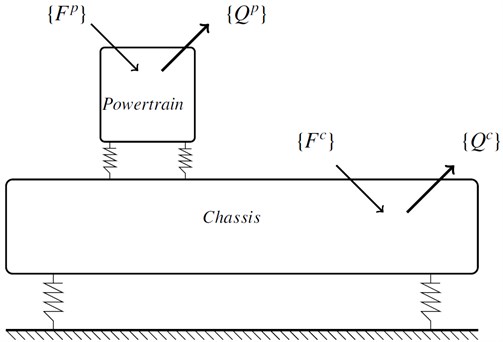
Since small displacements can be assumed, the powertrain is modeled by rigid body with time-invariant mass and inertial matrix. It is supported by mounts on the vehicle chassis that is modeled as a suspended body. The chassis is not considered as a rigid body, but it behaves like an elastic solid with its own characteristic frequencies. The mounts commonly used in powertrain mounting system are bonded metal-rubber construction. Hydraulic or pneumatic supports are generally used to control the interaction between the powertrain and the chassis for better vibration isolation. The engine mounts are represented by three sets of constant stiffnesses and dampings. No rotational stiffness of the mounts has been considered. The complex stiffness matrix of a mount can be written in the local coordinate system as [9]:
The superscript and the subscript correspond to the mount coordinate system of the th mount. The stiffness matrices must be transformed from the local coordinate system to the global coordinate system by the classical linear transformation:
where is the transformation matrix from the local coordinate system to the global one .
2.2. Equation of dynamic equilibrium of the powertrain
A generalized vector is defined by combining translational and rotational displacements of the center of gravity of the powertrain with respect to :
It has been shown [6] that this generalized displacement vector which describes the vibrational behavior of the powertrain satisfies the following differential equation:
The superscripts and stand for powertrain and chassis respectively. In the case of harmonic excitations, displacements are also harmonic , thus the above equation becomes:
The physical meaning of the terms that appear in this equation are given below:
• is the mass matrix composed of the mass and the inertia tensor expressed at the center of mass :
• contains forces and torques applied on the powertrain. It results in gas explosions in the cylinders and inertial efforts due to moving masses in the engine.
• is the sum of the excitations applied by each mount on the powertrain; .
It has been shown [6] that the generalized force applied to the powertrain and caused by all the mounts can be written as:
represents the stiffness matrix of the powertrain with the mounts:
is defined by the position of the th mount's center of elasticity with respect to the center of gravity of the powertrain:
is formed by the coupling terms between the powertrain and the chassis:
contains all the translational degrees of freedom of the nodes which belong to the chassis and attached to the powertrain. Equations (5) and (7) give:
The matrix and the vector are used instead of and . is obtained by completing matrix with zeros as follows:
contains the degrees of freedom of all nodes in the chassis: .
Finally, the equation describing the vibrational behaviour of the powertrain coupled to the chassis is given by:
2.3. Equation of dynamic equilibrium of the chassis using a modal approach
The following equation describes the vibrational behaviour of the chassis:
Matrices , and are respectively the mass, damping and stiffness matrices of the chassis. These matrices are not needed, but are only used in this study for the presentation of the method. However the modal solutions, measured or calculated, must be known.
represents interaction force applied by the powertrain on the chassis. It has been shown [6] that this force can be written as:
and are defined by:
and:
Combination of (14) and (15) gives:
Again, matrices and are used instead of matrices and :
Finally, the equation of motion of the chassis expressed in terms of its physical degrees of freedom is obtained:
2.4. Coupling equation
As a general rule, displacement caused by linear vibrations of an elastic solid structure with constant boundary conditions such as the chassis can be expressed by using the modal basis matrix . Such a basis can be determined analytically, numerically or experimentally. If this principle is applied, the displacement vector of the chassis can be written as:
or with a matrix form:
is the modal matrix with the first modes of the chassis; . is the modal contribution vector; . The matrix satisfies the following ortho-normality relationship:
After multiplication by , and taking into account (22), equation (20) becomes:
with:
Coupling equation of the powertrain with the chassis is obtained from (24) and (13):
3. Coupling matrix and spectral radius
3.1. Coupling matrix
Let us define by:
is the impedance of the powetrain without any interaction with the chassis.
So is the displacement of the powertrain caused by the force when the chassis is fixed.
In the same way, will be the impedance of the chassis without any interaction with the powertrain:
the modal displacement vector due to the force applied on the chassis without any interaction with the powertrain is:
Coupling equation between powertrain and chassis becomes:
with:
Equation (28) can be written as:
These relations show that the responses of the coupled subsystems are the ones of the blocked uncoupled subsystems plus the interaction terms. The displacements of the coupled subsystems are deduced from the blocked uncoupled displacements by using the equation:
When convergence is verified, equation (30) can be solved iteratively by using a series expansion of :
Equation (31) becomes:
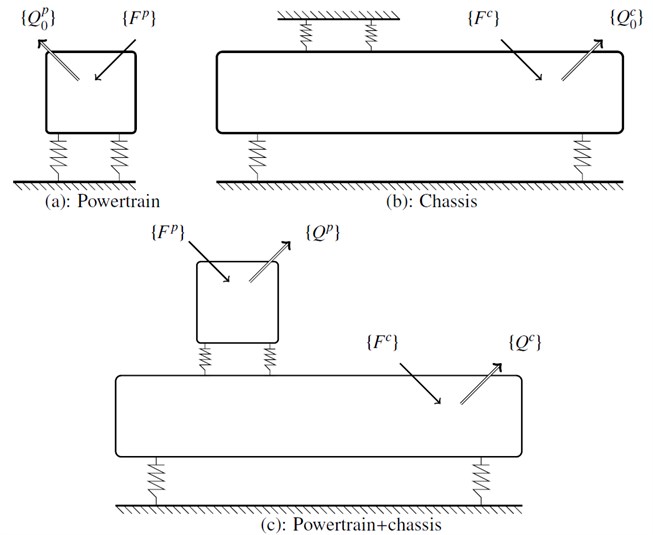
Figure 2 shows schematically the principle of the method. It allows the deduction of the behaviour of the overall system from the displacements of the grounded powertrain and the chassis independently. Convergence of (33) is related to the spectral radius of the coupling matrix and defined by:
where are the eigenvalues of . (33) converges if . This means that there is a weak coupling between the powertrain and the chassis. The larger the eigenvalue, the stronger the coupling between the chassis and the powertrain will be.
Fig. 2Methodology: a) grounded powertrain subjected to the excitation Fp, b) chassis subjected to the excitation Fc, c) displacement Qc of the system deduced from Q0p and Q0c
3.2. Second order approximation
The objective is to achieve a simplified expression of the second order expansion of (34):
With:
In this case:
and:
Thus, the modal displacement vector of the chassis due to the interaction forces caused by its coupling with the powertrain can be written as:
The expansion of to the second order contains only one term because the excitations directly applied on the chassis are not taken into account in the present study. In this case, the previous expression of becomes:
Or by replacing  by its value:
Equations (39) allow the prediction of the displacement vector of the chassis coupled to the powertrain. These equations need the modal solutions of the chassis, coupling matrix and displacement of the uncoupled powertrain . This first approximation depends on the number of modes selected. However, the equation (39) can be further simplified as it contains an inversion matrix. In the next section, further simplifications are proposed with appropriate assumptions. In the next section, further simplifications are proposed with appropriate assumptions.
3.3. Approximations
Assuming that the matrix of modal damping is diagonal, one can see that all matrices contained in the impedance are diagonal, except the matrix . Therefore, only the diagonal elements of the matrix are kept in order to avoid the matrix inversion. In this case:
with:
Physical displacements are:
Thus equation (41) allows the prediction of the physical movement of any point on the chassis from the following parameters:
• : physical displacement of point on the chassis.
• : th component of mode shape number of the chassis. These mode shapes can be obtained by measurement, identification or numerical simulation.
• : coupling stiffness matrix between the powertrain and chassis. This matrix contains only the stiffness characteristics and the positions of mounts.
• : physical displacement of the center of mass of the grounded powertrain.
4. Application for an industrial case
The method which was verified on a simple beam model is applied now to a more complex bus model.
4.1. Used model
Fig. 3Finite element model of the bus
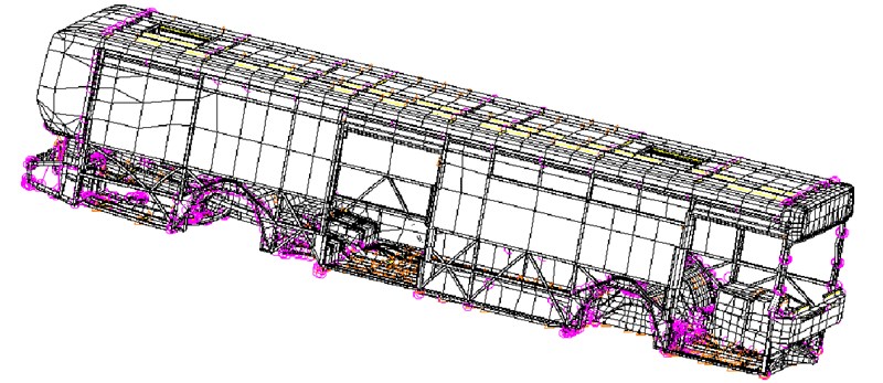
The studied structure is an "AGORA LINE" which is a city bus manufactured by IVECO and operated by the Paris public transport company RATP (Régie Autonome des Transports de Paris). The bus has a length of 12 meters and a mass of 8008 kg. The powertrain is manufactured by IVECO (CURSOR 8 F2B) with a mass of 1147 kg. Usually, the stiffnesses of the mounts are weakly dependent of the frequency and more significantly of the displacement. However, for the mounts which equip the tested city buses, a constant stiffness along the three directions was taken for modal calculations (106 N/m). The damping was also assumed to be constant (15000 Ns/m). The characteristics of the chassis, powertrain, and suspensions are given in the appendix.
The finite element model of the bus has 64146 degrees of freedom and 11885 elements. It basically consists of beams, plates and concentrated mass. For simplicity, axles, wheels and mass of passengers are not taken into account. The modal data of the chassis (modal and spectral matrices) were calculated by the commercial software Nastran. Figure 3 shows the mesh of the model used.
4.2. Results
Modal analysis of the bus provides 270 mode shapes in the frequency band [0-60 Hz]. 105 global modes were selected for the condensation of the model. Pitch and bounce mode shapes were found among these modes. The comparison of the spectral radius obtained by considering the complete model and the condensed model proposed by the present method shows that the influence of the condensation on the spectral radius is limited (see Figure 4).
Fig. 4Comparison between the values of the spectral radius obtained by the complete model and the condensed model
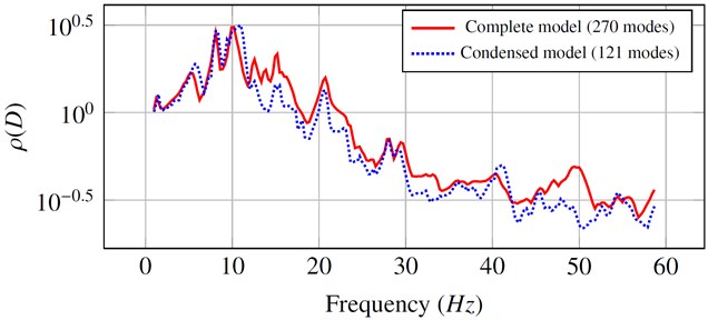
Fig. 5Acceleration v.s the frequency for the full model and the condensed model
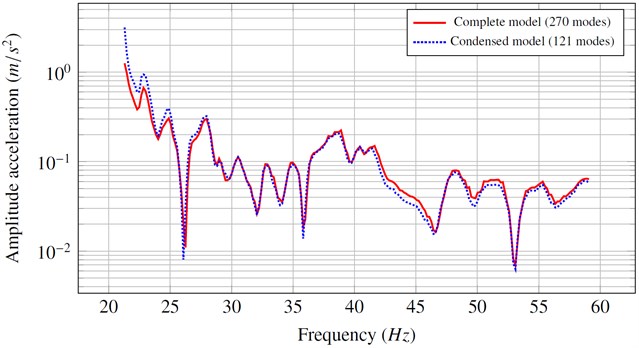
A dynamic torque with a constant amplitude (220 Nm) was applied to the powertrain. The curves in Figure 5 show the evolution of the vertical acceleration obtained near the driver's seat. The two curves are obtained by considering the full model and a condensed model thanks to the expansion to the second order of the coupling terms. One can see that the two curves are close over the frequency from which the convergence is verified (spectral radius < 1).
Figure 6 shows the effect of the approximation developed in paragraph 2.3 (eqs. (40), (41)) which takes into account the diagonal form of the generalized damping matrix of the chassis, in addition to second order expansion of the coupling terms. We note that the amplitude and the phase of the two curves are similar.
Fig. 6Amplitude and phase of the acceleration obtained from simplified and complete calculation
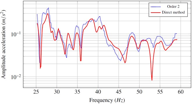
a)
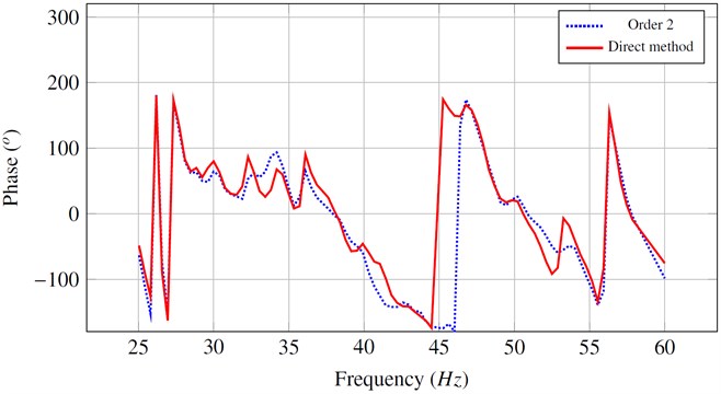
b)
5. Conclusions
This study examines the interactions between subsystems, in particular, the interaction between powertrain and chassis applied to the case of a city bus for which the main disturbance comes from the powertrain since during operation, the average of driving time is less than the average stopping time. To correctly predict the traditional dynamic responses of the chassis caused by the disturbance of the powertrain, it is essential to be able to analyse the phenomena induced by the coupling, over all the excitation frequencies. The general equations of motion of the chassis and the powertrain are reformulated by using a coupling matrix, independent of the external excitation. This coupling matrix is the base of the response analysis of the chassis coupled to the powertrain. The order of coupling between the two subsystems defines their valid range of frequency. The analysis based on the concept of coupling matrix leads to a simpler expression of the physical movement of the chassis caused by its coupling with the powertrain. Despite its sensitivity to the degree of coupling, this method was applied to the case of the interaction between the chassis and drivetrain of a vehicle with an elongated elastic chassis, as the case of a city bus. Results obtained from this industrial study confirm that, as in the case of the simple example, the condensation method can be applied to more complex systems.
References
-
E. Courteille, F. Mortier, L. Lotoing, E. Ragneau. New analytical method to evaluate the powerplant and chassis coupling in the improvement vehicle nvh. European Journal of Mechanics – A/Solids, Vol. 24, Issue 6, 2005, p. 929-943.
-
Jae-Yeol Park, Rajendra Singh. Effect of non-proportional damping on the torque roll axis decoupling of an engine mounting system. Journal of Sound and Vibration, Vol. 313, 2008, p. 841-857.
-
Taeseok Jeong, Rajendra Singh. Analytical methods of decoupling the automotive engine torque roll axis. Journal of Sound and Vibration, Vol. 234, Issue 1, 2000, p. 85-114.
-
J. A. Snyman, P. S. Heyns, P. J. Vermrulen. Vibration isolation of a mounted engine through optimization. Mech. Math. Theory, Vol. 30, Issue 1, 1995, p. 109-118.
-
Shilin Xiea, Siu Wing Ora, Helen Lai Wa Chana, Ping Kong Choyb. Analysis of vibration power flow from a vibrating machinery to a floating elastic panel. Mechanical Systems and Signal Processing, Vol. 21, Issue 1, 2007, p. 389-404.
-
Ali El Hafidi, Bruno Martin, Alexandre Loredo, Eric Jegoc. Vibration reduction on city buses: determination of optimal position of engine mounts. Mechanical Systems and Signal Processing, Vol. 24, Issue 7, 2010, p. 2198-2209.
-
E. Gego. Contribution L’Amelioration Du Confort Vibratoire Dans Les Autobus. Ph. D. Thesis, Universit De Bourgogne, 2008.
-
Rajendra Singh, Jin-Fang Hu. Improved torque roll axis decoupling axiom for a powertrain mounting system in the presence of a compliant base. Journal of Sound and Vibration, Vol. 331, 2012, p. 1498-1518.
-
C. M. Harris. Shock and Vibration Handbook, Chapter 3. McGraw-Hill, New York, 1995.
-
J. S. Arora, P. Eriksson. A comparison of global optimization algorithms applied to ride comfort optimization problem. Structural and Multidisciplinary Optimization, Vol. 24, 2002, p. 157-167.
-
J. S. Arora, P. Eriksson. A Ride Comfort Design Sensitivity Analysis of a City Bus. SAE Paper, 2001.
-
Rajendra Singh, Jae-Yeol Park. Role of spectrally varying mount properties in influencing coupling between powertrain motions under torque excitation. Journal of Sound and Vibration, Vol. 329, 2010, p. 2895-2914.
-
R. A. Ibrahim. Recent advances in nonlinear passive vibration isolators. Journal of Sound and Vibration, Vol. 314, 2009, p. 371-452.
-
R. V. Dukkipati, Y. Yu, N. G. Naganathan. Review of automotive vehicle engine mounting systems. International Journal of Vehicle Design, Vol. 24, Issue 4, 2000, p. 299-319.
-
R. Singh, S. He. Estimation of amplitude and frequency dependent parameters of hydraulic engine mount given limited dynamic stiffness measurements. Noise Control Engineering Journal, Vol. 53, Issue 6, 2005, p. 271-285.
About this article

