Abstract
The paper presents a method for determining the vibration-damping elements for the mechanical system under consideration, necessary to obtain the desired amplitude value. The presented method is one of the mechanical system passive vibration reduction methods. The systems subjected to the passive reduction are systems obtained as a result of the dynamical characteristics identification. The structural and parametric identification was performed by using the method for synthesizing the dynamical distribution in the form of sluggishness and mobility.
1. Introduction
The studies on vibrations constitute an essential branch of the dynamics of technical systems, including machines, mechanisms and equipment. The analysis of the vibrations of mechanical systems are an important issue at the design stage, as well as at the stage of adjusting already operating machines to the requirements of manufacturing processes. Operating a machine near its resonant condition is possible only when the value of damping of the said system is large enough, due to the most significant tensions. Damping plays a decisive role in these cases, as it significantly reduces the amplitude of vibrations. There are many methods and technologies allowing a reduction of unwanted vibrations of the mechanical systems [1-20]. The methods can be divided into the following groups: passive vibration reduction [2, 4, 5, 13, 15, 16, 17, 19, 20], active vibration reduction [4-12, 15, 18, 19, 20] and semi-active vibration reduction [14]. The usual method of vibration reduction is through the introduction of dampers (passive vibration reduction) to the object. Such task may be accomplished with the use of the synthesis [1-10] and analysis algorithm [4, 11-20]. The research on the passive and active synthesis of vibrations mechanical systems is developed by the authors of this paper [6-10]. The scope of this paper is a method of selecting the dynamical parameters of mechanical systems on the grounds of the synthesis algorithm. Such task may be regarded as a support of the stage of designing mechanical systems, where an essential element is the fulfillment of the required dynamical properties. This paper formulates and formalizes the task of synthesis as a tool of passive vibration reduction. The passive vibration reduction in the system is made possible thanks to the elements called vibration dampers. The features of those vibration dampers include the lack of variability over time for their parameters and the fact that they do not deliver energy to the system. The above-mentioned components of the passive vibration reduction do not require any external power source, using solely the system motion to induce the vibration reduction forces.
To determine the passive values for the vibration damping elements it is necessary to define the free vibration drop coefficient for the resonance frequency at which the amplitude reaches the desired value. The pre-set amplitude is equal to the maximum displacement of the inertial element corresponding to the response of the system at the unit amplitude of the exciting force. The drop coefficient can be determined by using a graphical method assuming that the amplitude value and the graphical form of dynamical characteristics under consideration are known.
2. Dynamical properties of the system class under consideration
Before commencing the passive vibration reduction process, it is necessary to formulate the dynamical properties of the system class searched, passive vibration reduction, in the form of characteristic sluggishness or mobility functions. To determine the analytic form of the above-mentioned functions, it is necessary to provide the resonance and anti-resonance frequencies of the identified system and the conditions for passive vibration reduction. The passive vibration reduction conditions are defined in the paper, as the values of free vibration frequency drop coefficient. The above-mentioned properties assume the following analytic form:
hence:
where – free vibration frequency drop coefficient, – the frequency (resonance, anti-resonance) of damped vibrations, – the frequency (resonance, anti-resonance) of free vibrations, and – the roots (zeroes, poles) of the dynamical characteristics.
Using the dynamical properties of the identified system, in the form of resonance and anti-resonance frequency values and the determined free vibration frequency drop coefficient , results in obtaining the characteristic functions of the complex variable  in the form of sluggishness or mobility for restrained (3), (5) and semi-definite systems:
where – the constant of proportionality, – Laplace operator, – the number of resonance frequencies, – the number of anti-resonance frequencies.
The presented analytic form for the dynamical characteristics of the searched systems constitutes a starting point for applying the synthesis methods in the process of passive vibration reduction. The value of free vibration drop coefficient can be defined based on the desired vibration amplitude to be obtained by the searched system at the appropriate resonance frequency. The pre-set amplitude is equal to the maximum inertial element displacement corresponding to the system response at the unit amplitude of exciting force. If the value of this amplitude is known, then it is possible to define the value of coefficient by using the graphical interpretation presenting the desired dynamical properties. Depending on the vibration amplitude for the desired kinematic value, the following graphs are considered: susceptibility, mobility and the apparent mass.
Let the value of maximum displacement that can be obtained by the inertial element used to calculate the dynamical characteristics in the form of sluggishness or mobility is given. In such a case, to determine coefficient , it is necessary to generate the susceptibility graph in the form of function of two variables depending on the restrained:
or semi-definite systems under consideration:
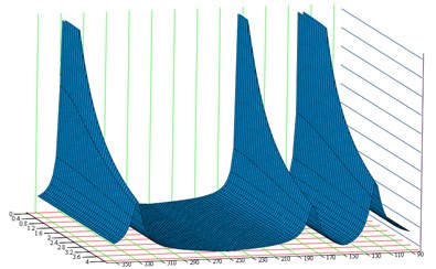
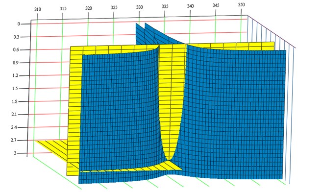
Fig. 1Dynamical characteristics of susceptibility Y(s,h)
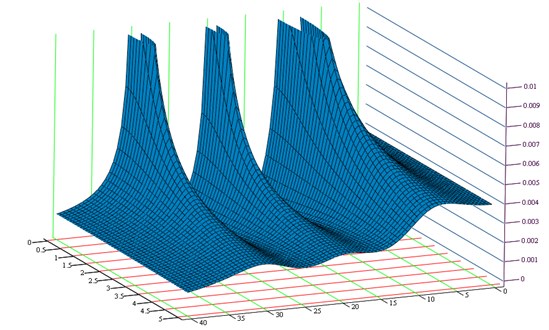
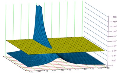
Fig. 2Plane YA(s,h)=Amax defining the characteristic points of the susceptibility function corresponding to the desired amplitude
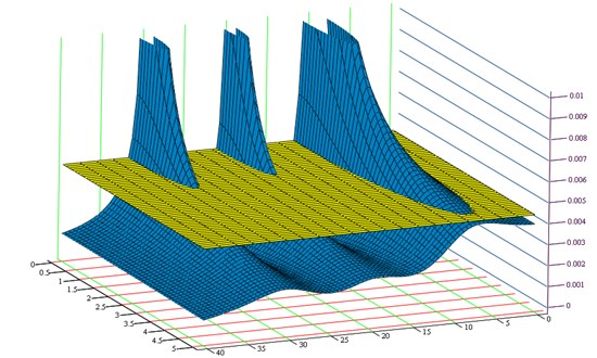
Figure 1 presents the graph of changes in susceptibility function amplitude depending on the free vibration frequency drop coefficient , at , and known resonance and anti-resonance frequency values. Assuming the value of vibration amplitude to be reached by the system when resonance or beat occurs makes it possible to determine equation . The above-presented plane equation together with the susceptibility graph creates characteristic points corresponding to the amplitude of selected resonance frequencies, depending on coefficient searched (Fig. 2). By projecting the points created by superimposing both graphs (intersections) into a complex plane, it is possible to determine a coordinate corresponding to the free vibration frequency drop coefficient value for the selected resonance frequency (Fig. 3). By taking into account the free vibration frequency drop coefficient (desired vibration amplitude) and the required resonance and anti-resonance frequencies, it is possible to determine the analytic form of dynamical characteristics subjected to synthesis. The functions of sluggishness and mobility obtained by using the desired dynamical properties describe a passive vibration reduction system. The functions defined in that way constitute the basis for using the synthesis methods in the passive vibration reduction process.
Fig. 3Graphical interpretation for determining the free vibration frequency drop coefficient h depending on the desired vibration amplitude: a) selected resonance frequency, b) plane in projection YA(s,h)=Amax
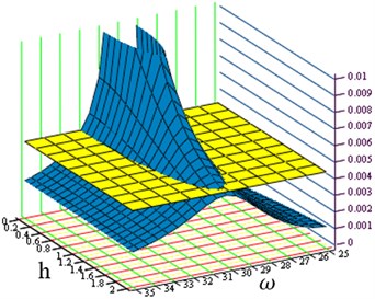
a)
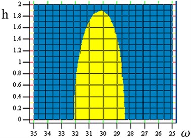
b)
3. Passive vibration reduction as a damping element proportional to the elastic element
The passive vibration reduction when the searched damping element value is proportional to the elastic element value is one of the indirect methods for synthesizing damped systems. Characteristic for the searched damping element is the fact that it is combined with the elastic element creating a parallel structure. The structural model for the linkage of damping and elastic elements is referred to as the Kelvin-Voigt model and hereinafter this name will refer to this very structure.
Let the dynamical properties in the form of resonance and anti-resonance values for the identified (synthesized) system are known, i.e.:
– the poles of the mobility function,
– the zeroes of the mobility function,
and the desired vibration amplitude of the inertial two-node element by assuming that these are Kelvin-Voigt model damping elements that constitute the vibration reduction elements of the searched system. In this case the value of two-node damping element is directly proportional to the elastic element value, which can be expressed by the following equation (11):
where – the value of two-node damping element, – the value of two-node elastic element, – the constant of proportionality.
The value of the constant of proportionality depends on the value of determined free vibration frequency drop coefficient in the following way:
where – the value of resonance frequency at the desired amplitude , – the value of free vibration frequency drop coefficient corresponds to the value .
In the case of the coefficient determined that way, it is necessary to calculate subsequent drop coefficients for remaining resonance and anti-resonance frequencies in the following way:
Finally, the dynamical characteristics of the searched passive vibration reduction system adopt the form of sluggishness (3), (4) or mobility (5), (6).
The determined characteristic functions describing the restrained systems take the form of sluggishness:
or mobility:
to be presented in the form making it possible to perform the process of inertial and elastic parameter identification of the system subjected to passive vibration reduction. In the above-presented case, the sluggishness (14) and mobility (15) take the analytic form taking into account solely the dynamical properties in the form of resonance and anti-resonance frequency sequence:
Functions (16), (17) are subject to direct identification by using the synthesis methods described in chapter two. By using the mixed method combined with the algorithm for determining the elastic type characteristics, the dynamical characteristics in the form of sluggishness (16) and mobility (17) are analyzed, giving:
where – the values of inertial elements, – the values of restrained elastic elements, – the values of elastic elements determined by using a mixed method, – the values of elastic elements of the identified system determined by using the algorithm for determining elastic type characteristics.
Taking into account the determined constant of proportionality (12) it is possible to calculate the values of vibration reduction elements using the following formula:
where – the values of rigidity for the identified system.
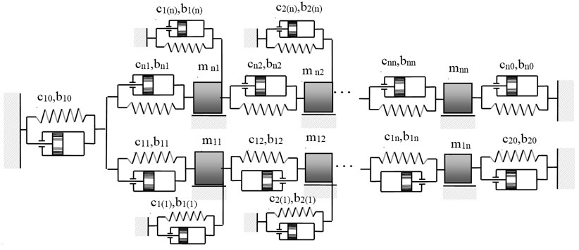
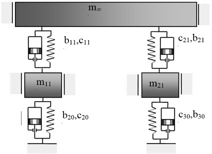
As a result of the passive vibration reduction performed, it is possible to obtain a system with the dynamical characteristics compliant with the adopted dynamical properties in the form of sluggishness (14) or mobility (15). The systems obtained as a result of using the mixed synthesis method and the passive vibration reduction are presented in Figures 4 and 5.
Fig. 4Structure of mechanical system obtained as a result of applying the passive vibration reduction in the case of properties described in the form (14)
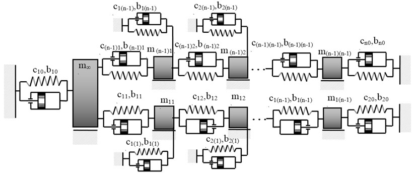
Fig. 5Structure of mechanical system obtained as a result of applying the passive vibration reduction in the case of properties described in the form (15)
4. Numerical example
Let the requirements to be met by the searched system are known and provided in the form of resonance and anti-resonance frequency sequence and the desired vibration amplitude:
Based on the dynamical properties (21) it is possible to determine the dynamical characteristics, subject to identification aimed at determining the parameters of inertial, elastic and passive vibration reduction elements. The characteristic function under consideration takes the form of positive, real-valued sluggishness function, in the following form:
At the subsequent stage of the passive vibration reduction system identification, it is necessary to determine individual free vibration drop coefficients , corresponding to selected resonance and anti-resonance frequencies. The free vibration drop coefficients can be determined based on the desired vibration amplitude for the resonance frequency in accordance with the formalism formulated in chapter 3. To do this, it is necessary to determine the susceptibility function and plane (Fig. 6a and Fig. 6b). For the frequency under consideration and the desired vibration amplitude , it is possible to determine the free vibration coefficient (Fig. 7). The identified free vibration coefficient drop takes the following value:
The determined free vibration drop coefficient makes it possible to select individual coefficients of the sluggishness function (22), depending on the type of passive vibration reduction applied.
Fig. 6Defining the requirements for characteristics: a) dynamical characteristics of susceptibility, b) selected frequency ωb3=330rads plane YA(s,h)=Ab3
a)
b)
Fig. 7Graphical interpretation for determining the free vibration frequency drop coefficient hb3 depending on the pre-set vibration amplitude
To identify the parameters of the system subject to passive vibration reduction, it is necessary to synthesize the dynamical characteristics describing the properties of the system without damping. In this case the characteristics (22) take the form of sluggishness describing non-damped vibration in the following form:
Synthesizing the sluggishness function (24) using the mixed method results in obtaining a characteristic function in the following form:
where
Assuming that the passive vibration reduction element is the two-node damping element with a value proportional to the value of elastic elements, then, the free vibration drop coefficients of the function (22) take the following value:
hence:
where – the constant of proportionality.
Taking into account the character of the existing passive element and determined drop coefficients, the dynamical characteristics (23) takes the following analytic form:
The passive vibration damping elements can be determined using the following dependence:
where – the value of two-node damping element, – the value of two-node elastic element, – the constant of proportionality.
By using the dependence (30), it is possible to determine the values of searched two-node damping elements in the case depending on the structures obtained:
Fig. 8Structure of mechanical system obtained as a result of applying the passive vibration reduction in the case of properties described in the form (29)
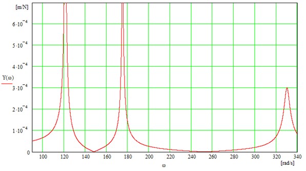
As a result of checking the obtained results for correctness, a graph for the susceptibility function (Fig. 9) of the system (Fig. 8) in relation to the inertial element was determined, whose properties comply with the desired requirements regarding the identified passive vibration reduction system, presented in the figure.
Fig. 9Dynamical characteristics for the susceptibility of systems obtained as a result of passive vibration reduction performed
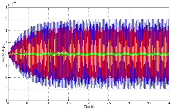
Analysis of the results was carried out in the Matlab/Simulink package. In the simulation, the excitation signal was determined as a force with a unit amplitude and circular frequency corresponding to the third resonant frequency of natural vibrations of the system. Movements from the dynamic model are shown in Figure 10.
Fig. 10Movements of the system with excitation linked to the third resonant frequency of the system
5. Conclusions
By performing the passive vibration reduction in mechanical systems supported by synthesis methods, a sequence of structures and parameters applying to the dynamical characteristics in the form of resonance and anti-resonance frequencies is obtained. The set of models created that way constitutes a quality base of the identified object. One of those methods can be the structural or parametric sensitivity used to assess the impact of parameters on frequency changes. The presented problem of passive vibration reduction of the identified structure and system parameters makes it possible to determine the values of passive elements compliant with the required amplitude value. This approach to the passive system vibration reduction allows designers to control the values of vibration amplitude of the system under consideration.
References
-
Redfield R. C., Krishnan S. Dynamic system synthesis with a bond graph approach. Part I: Synthesis of one-port impedances. J. Dyn. Sys., Meas., Control, Vol. 115, No. 3, 1993, p. 357-363.
-
Redfield R. C. Dynamic system synthesis with a bond graph approach. Part II: Conceptual design of an inertial velocity indicator. J. Dyn. Sys., Meas., Control, Vol. 115, No. 3, 1993, p. 364-369.
-
Park J. S., Kim J. S. Dynamic system synthesis in term of bond graph prototypes. KSME International Journal, Vol. 12, Issue 3, 1998, p. 429-440.
-
Kolovsky M. Z. Nonlinear Dynamics of Active and Passive Systems of Vibration Protection. Springer, 1999.
-
Smith M. C. Synthesis of mechanical networks: the inerter. IEEE Trans. Autom. Control, Vol. 47, No. 10, 2002, p. 1648-1662.
-
Dzitkowski T., Dymarek A. Active synthesis of machine drive systems using a comparative method. Journal of Vibroengineering, Vol. 14, Issue 2, 2012, p. 528-533.
-
Dymarek A., Dzitkowski T. Method of active synthesis of discrete fixed mechanical systems. Journal of Vibroengineering, Vol. 14, Issue 2, 2012, p. 458-463.
-
Dzitkowski T., Dymarek A. Active synthesis of discrete systems as a tool for stabilisation vibration. Applied Mechanics and Materials, Vol. 307, 2013, p. 295-298.
-
Dymarek A., Dzitkowski T. Reduction vibration of mechanical systems. Applied Mechanics and Materials, Vol. 307, 2013, p. 257-260.
-
Dymarek A., Dzitkowski T. Active synthesis of discrete systems as a tool for reduction vibration. Solid State Phenomena, Vol. 198, 2013, p. 427-432.
-
Kovarorova J., Schelgel J., Dupal J. Vibration control of cantilever beam. Journal of Vibroengineering, Vol. 9, Issue 2, 2007, p. 45-48.
-
Płaczek M. Dynamic characteristics of a piezoelectric transducer with structural damping. Solid State Phenomena, Vol. 198, 2013, p. 633-638.
-
Marcinkevičius A. H. Theoretical analysis of vibrations of a mass connected with a support through a chain of elastic elements. Solid State Phenomena, Vol. 164, 2010, p. 303-307.
-
Liu Y., Hiroshi Matsuhisa H., Utsuno H. Semi-active vibration isolation system with variable stiffness and damping control. Journal of Sound and Vibration, Vol. 313, Issues 1-2, 2008, p. 16-28.
-
Kim S.-M., Wang S., Brennan M. J. Dynamic analysis and optimal design of a passive and an active piezo-electrical dynamic vibration absorber. Journal of Sound and Vibration, Vol. 330, Issue 4, 2011, p. 603-614.
-
Louroza M. A., Roitman N., Magluta C. Vibration reduction using passive absorption system with Coulomb damping. Mechanical Systems and Signal Processing, Vol. 19, Issue 3, 2005, p. 537-549.
-
Franchek M. A., Ryan M. W., Bernhard R. J. Adaptive passive vibration control. Journal of Sound and Vibration, Vol. 189, Issue 5, 1996, p. 565-585.
-
Alkhatib R., Golnaraghi M. F. Active structural vibration control: a review. The Shock and Vibration Digest, Vol. 35, No. 5, 2003, p. 367-383.
-
Craig J. J. Introduction to Robotics: Mechanics and Control. Addison-Wesley Publishing Company, 1989.
-
Mottershead J. E., Ram Y. M. Inverse eigenvalue problems in vibration absorption: passive modification and active control. Mechanical Systems and Signal Processing, Vol. 20, Issue 1, 2006, p. 5-44.
About this article

This work has been conducted as a part of the Research Project N 502 447239 supported by the Ministry of Science and Higher Education of Poland in 2010 – 2013.
