Abstract
This article presents derived methodological procedure of redesigning shaft, gear box, bucket wheel of bucket wheel excavator. Method of finite elements has been used for defining numerical model of shaft. As validation of the model, measurements of vibrations at characteristic points of gear box have been used. Obtained data in frequency domain proved correctness. This analysis is made for gear box of bucket wheel on bucket wheel excavator SRs2000 which operates at Kostolac coal basin in Serbia. On this basis, reconstruction of this structure has been performed.
1. Introduction
Bucket wheel excavator is the most complex and most important machine at an open cast mine, within system of continuous exploitation. Proper design and operation of bucket wheel excavator have major impact at reliability and viability of production. Drive units at bucket wheel excavator are basic components of torque transmission, which are enabling all linear and rotational motions, with final outcome of achieving of production. Therefore, highest significance is given to this component in this paper. Its dynamical behaviour and revitalization approach can be accepted as a baseline for other drive units on bucket wheel excavator.
Application of finite elements method in optimization and solving construction problems marked large part of the field of designing numerous different constructions. Large numbers of experts in different fields are engaged in area of finite elements method. Numerical approach to modeling is unique, but its application on certain constructions varies from example to example. In the same way this paper is unique for its application of finite elements method on working element of bucket wheel excavator. In addition, vibrodiagnostics as the proof of numerical model is also very often used in scientific papers. Nevertheless, there are only a small number of papers in expert journals, which in this way approach huge mining machineries, such as bucket wheel excavator.
The paper that analyses shaft fracture on bucket wheel of bucket wheel excavator in Poland has defined the cause of shaft fracture on bucket wheel, whereby load changes and their maximal amplitudes that caused the fracture have been determined. Discreet model of shaft has been made using the finite elements method [1]. The paper that analyses numerical and experimental analysis of fatigue in the case of non standard fracture of test piece has shown the finite elements method with simulation of different test pieces lengths [2]. Experimental verification of numerical model of huge axial bearing is defined using the finite elements method and measured load at characteristic points of axial bearing [3]. Mass unbalance of any system has extremely negative effect. Incident of mass unbalance due to eccentricity of elements in rotor-bearing system generates contact between them [4]. Large number of devices is set up on fundament which moves independently. Making of shaft model is defined on the basis of two shaft operating regimes: slow rotation and periodical motion (swinging) in the lower part of bearing reliance [5].
Behaviour and condition diagnostics of drive units at mining machines is of crucial importance for decision making related to their operation and maintenance, as well as to revitalization or modernization, including design of drive unit and other components of torque transmission with load bearing structure. Concept approach to this issue is firmly defined – analytical part is introduction to the problem, its modelling determines framework for engineering decision making and experimental part should confirm rectitude and accuracy of methodology in function of detection of anomaly source and its preventive rectifying.
Generally, behaviour diagnostics of drive units at mining machines, particularly on bucket wheel excavators, gained importance during 1990-ies, mainly because of two reasons. First reason was that very few bucket wheel excavators were manufactured during that period, while the machines in operation are several decades old. This led both manufacturers and operators of bucket wheel excavators to commence revitalization in order to extend their operational life and to retain or improve existing performances. Second reason was that bucket wheel drives on most of the machines are of old design with huge operation time. Solving of both these problems required numerical models and experiments based on measurement of vibrations.
Problems raised on bucket wheel excavators during operation are mainly caused by insufficiently well design of structure geometry, insufficient materials strength, close ratio of frequency stimulus and response of components, which could have bigger or smaller stiffness (source or precipice), etc. Appearance of all these factors is common [7]. Input shaft of the bucket wheel drive gear reduction is selected as a redesign example.
2. Computer model and dynamic calculation of the shaft
Efficient condition analysis and behaviour diagnostics of designed or manufactured is enabled by load distribution, membrane and bending stresses, deformation energy and kinetic and potential energy. Equivalent (comparative) stress is recalculated for all types of finite elements and global nodes.
In order to achieve good behaviour of structure or components during operation main goals should be as follows: largest possible difference between maximum stress and yielding stress, largest possible distribution of deformation, stress and energy, smallest possible presence of stress concentration, materials resistance to appearance and propagation of cracks, large ductility and toughness of materials, further dynamical response of probable stimulus, as high as possible first frequency and further possible distance between frequencies and smallest factor of dynamic amplification.
Computer modelling and calculation of structures by finite element method enables modelling and complex calculations and problem solving, determination of actual movement and stress situation, determination of actual behaviour of the structure, reliable prognosis of structure reaction in operation, providing of elements for decision making (regimes of operation, repairs, reconstructions, optimizations and verification of selection of structure solution), determination of poor behaviour or weakening of structure, estimation of operation life and period of reliable operation of structure.
Justification for such approach is represented by the fact that stress situation in structure depends on geometry (layout and dimension of load bearing components), load and mean of support, while on the other hand is not related to the type of material (linear analysis). Each possible minute stress reduction and concentration, which can be achieved with this approach, enables significant extension of operational life of structure together with large reliability increase.
Dynamic calculation encompasses determination of free oscillations, forced oscillations and distribution of kinetic and potential energy. All parameters within dynamic calculation are in function of time. Since the static calculation is a special case of dynamic one (time ) global matrix of stiffness remains the same, i.e. it is formed in the same way. During dynamical analysis, beside static forces, finite element is exposed to dynamical forces (inertial and dampening forces) [7, 8].
Basic dynamical equation of forced dampened oscillations, given as matrix in global system is:
where – mass matrix, – factor of dampening, – stiffness matrix, , , – acceleration, velocity and deformation, – dynamic load vector, – time [8, 9].
Main shapes of oscillating have deformation shapes under "imaginary" load. Worst structure behaviour is enunciated by first shape of oscillation, and so on. Structure has good dynamic behaviour if:
- first frequency is high and
- spacing between frequencies is large.
This is possible to achieve in case that the structure is manufactures with maximal stiffness and minimal mass. Natural frequency is proportional , where is stiffness of the component, and is mass of the component [7-9].
Behaviour diagnostics of the shaft i.e. input shaft of the gear reduction or electric motor, as a main parameter of behaviour diagnostics of drive's components, is one of the most important vibro-diagnostic's parameter of gear reduction and electric motor behaviour. Due to numerous vibration sources isolation of natural frequencies and typical stimulus frequencies is of great importance for components, sub-constitutive units at any drive of bucket wheel excavator. Main form of oscillation comprises natural frequencies and their forms – main oscillating modes. It should be emphasised stimulus frequencies, which are represented as analytical part of frequency calculation. Typical parameters for determination of stimulus frequencies of shaft are as follows:
- [min-1] – number of shaft's revolutions, [Hz] – shaft's frequency, – number of shaft,
- – drive gear, – driven gear, – geared couple.
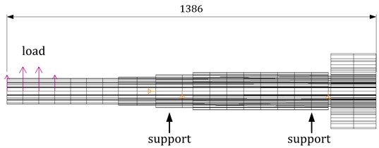
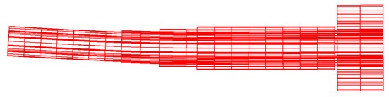
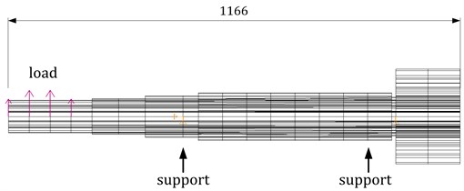
Parameters of stimulus frequencies of shaft are obtained based on known ration of revolutions and frequency (). Shaft modelling is performed by finite elements method i.e. by finite volume elements. Model and dynamical calculation of input gear reduction shaft, at bucket wheel excavator SRs2000 at Drmno open pit, is shown at Figs. 1 and 2, for two cases:
- input shaft, with total length 1386 mm, have part which is inserted into hydro-dynamical coupling, and as such is an old solution (Figs. 1 and 2),
- part which is inserted into hydro-dynamical coupling is shortened by 220 mm, and as such is a new solution.
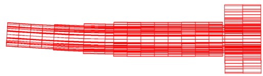
Fig. 1Old variant: computer model of input shaft SRs2000 and dynamical calculation, first frequency f01=34.3 Hz (2279 nodes, number of volume finite elements 1776)
a)
b)
For the first, old variant, of the input shaft, dynamical calculation provided value of the first frequency of 34.3 Hz, represented as the bending in vertical plane. Other frequencies are considerably higher and therefore shall not be considered. Shown load represents simulation of the hydro-dynamical coupling which introduced as a mass.
Model of input shaft and electric motor shaft, developed as beam model with first main shape of oscillations, is presented on Fig. 2. Values of natural frequencies of both shafts, in dependence of mass of the coupling at the end of the shaft, are given in Table 1.
Fig. 2Computer beam model of input shaft and electric motor shaft at SRs2000 excavator and dynamical calculation, old variant of input shaft
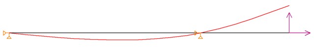
a) Shaft of the electric motor
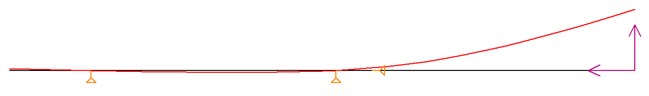
b) Gear reduction input shaft
Table 1Values of natural frequencies
Mass of coupling [kg] | 100 | 200 | 300 | 400 | 500 |
electric motor [Hz] | 71.1 | 60.6 | 52.8 | 47.1 | 42.9 |
gear reduction [Hz] | 62.8 | 45.8 | 37.8 | 32.9 | 29.6 |
Fig. 3New variant: computer model of input shaft SRs2000 and dynamical calculation, first frequency f01=61.0 Hz (2132 nodes, number of volume finite elements 1668)
a)
b)
Velocity of electric motor is 980 rpm, thus causing incentive frequency of 16.3 Hz, and all consecutive multipliers of this frequency, 2X, 3X, 4X etc. (2 x 16.3 = 32.6 Hz, which is near to the frequency of the shaft with coupling of the 400 kg). Based on dynamical calculation and stimulus frequencies we can conclude that it is much favourable to install heavier coupling at the electric motor side. If the heavier part is to be installed at the gear reduction side, then its mass must be smaller than 400 kg. It can be seen that beam modelling of the shaft, in some cases, corresponds to volume finite elements, regarding engineering accuracy with maximal error of 10 %. Fig. 3 shows the new shaft (model).
For the second variant of the input shaft, dynamical calculation resulted in first frequency of 61.0 Hz, represented as bending in vertical plane. Shaft is shortened by 220 mm. In this case, other frequencies are considerably higher, hence will not be considered. Considered load simulates hydro-dynamical coupling, represented as a mass, same as in previous case. Velocity of electric motor is 980 rpm, which causes stimulus frequency of 16.3 Hz. Shortening of the shaft provided increased stiffness, resulting in higher first frequency, where it is obvious that 2X, 3X and 4X stimulus frequencies do not correspond to first frequency of the shaft, i.e. these are outside of resonant field [6].
Cross section of gear reduction on SRs2000 bucket wheel excavator, with completed reconstruction on input shaft is shown on Fig. 4.
Fig. 4Cross section of gear reduction on SRs2000 bucket wheel excavator with marked position of shaft
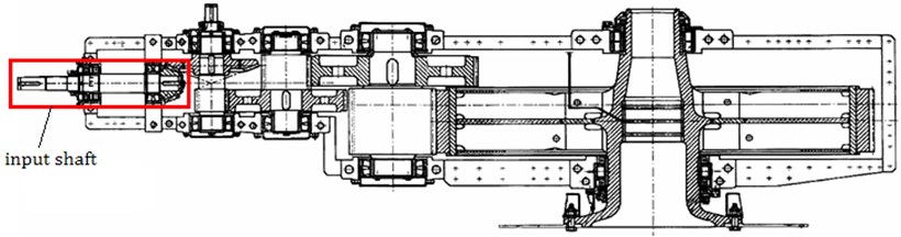
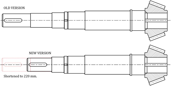
Input shaft before and after reconstruction is shown on Fig. 5. Main goal of this undertaking is reduction of shaft length. This increases its stiffness and results in higher stimulus frequency (61 Hz instead of 34.3 Hz), meaning larger distance from second incentive frequency.
Fig. 5Old and new versions of input shaft
3. Shaft’s experimental measurements results (vibration measurement)
Vibration measurement of input shaft at bucket wheel drive on SRs2000 excavator, which operates at Drmno open pit, is performed by three-component device: acceleration sensor, analogue-digital (AD) signal converter and USB port for communication with PC. Applied software supports analyses of time and frequency acceleration signals. Frequency signal is obtained by FFT (Fast Fourier Transform). Measuring equipment and software for processing are developed by MikroElektronika Company, from Belgrade, Serbia.
Signal in frequency domain, measured at typical location on gear reduction input shaft of bucket wheel drive of SRs2000 excavator. This input shaft was not redesigned, therefore it is longer by 220 mm in comparison to new variant. Vibrations measurement location‚ which will provide actual condition of input shaft is at the location of the bearing.
Fig. 6Frequency acceleration signal at measuring location of input shaft of bucket wheel drive at SRs2000 excavator, with selected acceleration frequency signals at 16.3 Hz and 34.3 Hz
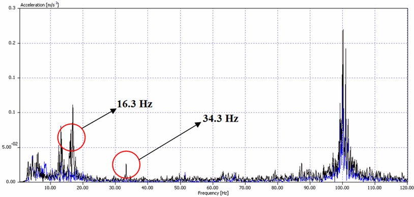
Input shaft of bucket wheel drive at SRs2000 excavator has two typical signals. Signal of 16.3 Hz is signal of shaft revolution at 980 rpm, while signal at 34.3 is first natural frequency of the shaft in the plane, which is near to the second harmonic of stimulus (Fig. 6). Lower first natural frequency indicates lower stiffness of this shaft despite increased mass, which is geometrically unevenly distributed (longer console part toward coupling, i.e. electric motor) [6].
Fig. 7Frequency acceleration signal at measuring location of input shaft of bucket wheel drive at SRs2000 excavator, with selected acceleration frequency signals at 16.3 Hz and 61 Hz
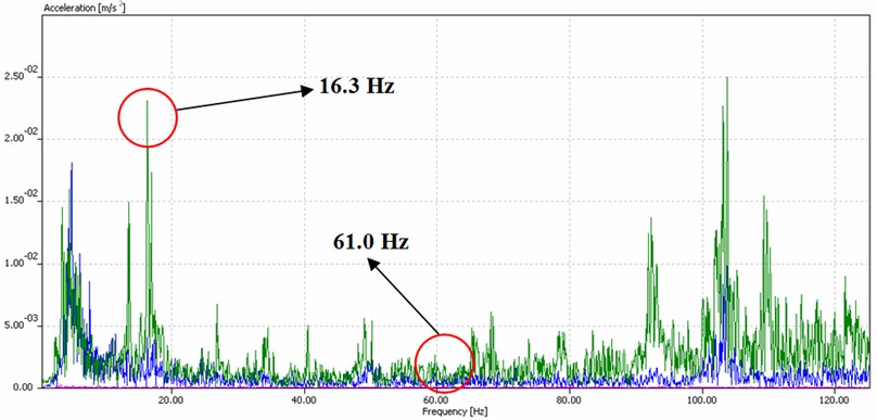
Measured signals in frequency domain are shown in Fig. 7, which are taken on typical location of redesigned input shaft of gear reduction at bucket wheel drive of SRs2000 excavator.
Two signals are selected, which are typical for input shaft of gear reduction of bucket wheel drive. This shaft is redesigned, meaning that it is shortened by 220 mm, thus impacting stiffness of the shaft and whole sub-unit. Signal of 16.3 Hz is signal of shaft revolution at 980 rpm, while signal at 61 is first natural frequency of the shaft in the plane. Amplitudes for this system are considerably lower, indicating proper sizing and stiffness level, while signal sliding due to system's stiffness, i.e. lubricating, for typical signals of elements within lubricating system [6].
Amplitudes of redesigned input shaft are lower in comparison to old design:
- ratio of stimulus frequencies amplitudes at 16.3 Hz:
, ratio is ;
- ratio of natural frequency amplitudes (34.3 and 61 Hz):
, ratio .
Further more, behaviour of whole drive unit is better at lower amplitudes and higher frequencies. Overview of first ten natural frequencies of dynamical calculation is given in Table 2, for both cases as well as stiffness for both variants.
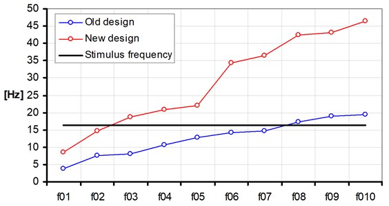
Comparison diagram of first ten frequencies of new and old design is shown on Fig. 8 [6].
Table 2First ten natural frequencies of old and new designs of bucket wheel drive at SRs2000 excavator
Hz | ||||||||||
Old design | 3.7 | 7.6 | 8.0 | 10.7 | 12.9 | 14.1 | 14.8 | 17.3 | 18.9 | 19.5 |
New design | 8.6 | 14.6 | 18.7 | 20.8 | 22.1 | 34.3 | 36.5 | 42.5 | 43.1 | 46.5 |
Fig. 8First ten natural frequencies of old and new design of input shaft at gear reduction on bucket wheel drive
4. Conclusion
Dynamical behaviour of the bucket wheel drive unit largely depends on gear reduction type, load bearing structure design, torque lever i.e. motor carrier, supports of the drive unit, age and operation time (existence of gaps and wearing at torque transmission components), manufacturing variations of components (shafts, gears, bearings), basic input parameters (revolutions per minute, torque, force on the bucket, voltage, etc.).
Input shaft of the gear reduction is main indicator of dynamical behaviour of drive unit. The shaft must have proper stiffness (higher natural frequency) and at the same time it must be optimized regarding sizing and geometry, i.e. console part toward coupling must be shorter or equal in length as the spacing between bearings in the gear reduction. In this manner overlapping of natural frequency and rotation frequency – stimulus is avoided, thus enabling installation of coupling on the input side of the gear reduction. Similar relationship is valid for the rotor shaft of the electric motor, although research showed that installation of heavier half of the coupling at the rotor shaft provides better results due to larger stiffness and higher first frequency.
Reduction of shaft length increases its stiffness. This was the main goal, since stimulus frequency was increased from 61 Hz to 34.3 Hz. Purpose for this is to increase distance from second incentive frequency. This undertaking increases operational life of input shaft, as well as operational life of gear reduction of the bucket wheel drive of the excavator.
References
-
Rusinski E., Harnatkiewicz P., Kowalczyk M., Moczko P. Examination of the causes of a bucket wheel fracture in a bucket wheel excavator. Engineering Failure Analysis, Vol. 17, Issue 6, 2010, p. 1300-1312.
-
Kovše I. Numerical and experimental analyses of fatigue in a non-standard fracture-mechanics specimen. Journal Materials and Technology, Vol. 37, 2003, p. 39-43.
-
Kunc R., Žerovnik A., Žvokelj M., Prebil I. Numerical determination of the carrying capacity of rolling rotational connections. Journal Materials and Technology, Vol. 41, Issue 2, 2007, p. 73-76.
-
Xiaoyao Shen, Jiuhong Jia, Mein Zhao. Numerical analysis of a rub-impact rotor-bearing system with mass unbalance. Journal of Vibration and Control, Vol. 13, Issue 12, 2007, p. 1819-1834.
-
Ludmila Banakh, Grigory Panovko. Oscillations of shaft on vibrating foundation. Journal of Vibroengineering, Vol. 11, Issue 3, 2009, p. 415-420.
-
Jovančić Predrag. Behaviour Diagnostics of Drive for Bucket Wheel Excavators in Order to Revitalization. University of Belgrade, Dissertation, 2007, (in Serbian).
-
Jovančić Predrag, Tanasijević Miloš, Ignjatović Dragan. Relation between numerical model and vibration: behavior diagnosis for bucket wheel drive assembly at the bucket wheel excavator. Journal of Vibroengineering, Vol. 12, Issue 4, 2010, p. 500-513.
-
Maneski Taško. Computer Modeling and Calculation of Structures. Faculty of Mechanical Engineering, Belgrade, 1998, (in Serbian).
-
Maneski Taško, Jovančić Predrag, Ignjatović Dragan, Milošević-Mitić Vesna, Maneski Miloš. Condition and behaviour diagnostics of drive groups on belt conveyors. Journal of Engineering Failure Analysis, Vol. 22, 2012, p. 28-37.
About this article

This article is a contribution to the Ministry of Science of Serbia Funded Projects TR035040 and TR033039.
