Abstract
Prediction of NVH parameters of driveline in construction phase is a significant topic nowadays because it can save time and development costs, but requires more complex mathematical models. This paper describes the use of MBS simulation tool for prediction of driveshaft vibration where shaft is modeled as a flexible body. MBS approach can take into account various input parameters, i.e. unbalanced mass of shaft, geometry deviation from ideal shape, mounting points of eccentricity or contact between the shaft and other parts of the driveline. MBS model of driveshaft was verified by measurement on a real vehicle.
1. Introduction
Driveline of a modern heavy duty vehicle must fulfill various requirements, those include: high reliability, low price, durability and at the same time meet legal regulations. There are strict requests for increasing the mechanical efficiency and NVH emissions reduction because in 2024, based on ECE regulation the outside noise of heavy duty vehicle category N3 must be reduced by 3 dB. There are also requests from market for quieter and more comfortable vehicle. The driving comfort is a very important parameter for marketability of a vehicle. It means that NVH emissions must be taken into account, already, in the early construction phase, especially on the off-road vehicles with all-wheel drive, where the drivelines are really complex. The complexity of driveline means that the driveline is an important NVH source on vehicle and could not be overlooked.
NVH component testing on a prototype vehicle is still crucial but is quite expensive and time consuming which slows down the development process. The computational method is utilized to predict component behavior in the development phase. MBS modeling approach is a prominent tool because it can be used for finding a satisfying compromise between the manufacturing cost and the NVH requirements.
2. Computational approach
2.1. Properties of computational model
Dynamic behavior of a driveshaft of a heavy duty vehicle is complex and therefore it needs an approach that allows to describe the shaft motion and also the shaft deformation. The MBS approach with the use of rigid and flexible bodies was employed. This approach allows the use of various input parameters, i.e. unbalanced mass, eccentricity of shaft mounts or deformed shape of the shaft.
The shaft is mounted in carriers which are attached to chassis via roller bearings. Therefore, it is necessary to take into account the stiffness of the whole mounting assembly. The mounting assembly stiffness analysis was calculated in ANSYS.
2.2. Modal reduced body creation
To calculate the shaft behavior in MBS interface it is necessary to create a modally reduced body which could be imported to MBS software. The point of modal reduction are the reduced flexible body degrees of freedom. Craig-Bampton method was used. This method divides degrees of freedom to constrain and normal modes.
The reduction was made in ANSYS, where SOLID 186 element was used for solid mesh creation and MPC 184 was used for creation of beam construction for transferring loads into MBS system.
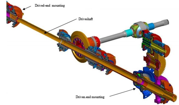
Fig. 1Drivetrain scheme
2.3. MBS model setup
The shaft was imported from ANSYS to ADAMS View as a flexible body via modal reduced body file (“mnf”).
Fig. 2MBS model scheme
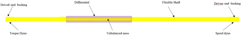
The shaft was supported by bushing element on the drived side. The bushing defines stiffness and damping of support. The drived-end support was realized by inserted rigid body which represents eccentricity of shaft supports. The rigid body was attached to ground by bushing element.
The torque was applied to drived side of the shaft. The amount of torque was calculated from engine torque characteristic and gear ratio to the driveshaft. The speed dyno was placed on the driven side of the shaft. Speed dyno limits speed range of the shaft to 500-3000 min-1. The maximal shaft speed was set according to operating conditions with the highest gear engaged.
The rigid body was attached to the mnf mesh in the middle of the shaft as a representation of unbalanced mass.
The shaft is going through the differential cage of second front axle in the central part, as it is shown in Fig. 2. The large amplitudes of whirling vibrations were estimated so that it is necessary to consider the contact between the shaft and differential cage. The contact was realized by Adams Impact function. Impact function was defined as flexible and rigid body contact with stiffness and damping. The contact was considered as frictionless.
2.4. MBS simulation results
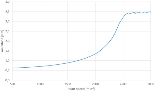
The MBS computational model outputs were torsional and whirling vibrations. Whirling vibration amplitude was significant and has impact on other vehicle structures.
Fig. 3Simulated results
3. Verification of the computational model
The shaft was measured on steady vehicle, for this measurement it was necessary to remove ring gears from wheel planetary reductions. All wheel drive was activated and all differentials were set to closed position during the measurement.
At the beginning of the measurement, was detected that driveshaft was bent 0.95 mm in minimal revolutions. It means that the shaft was bent also in the steady state.
The measurement was performed in range 500-3000 min-1.
Fig. 4Measured results
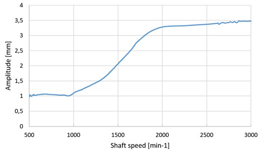
Fig. 4 shows that the shaft deviation increases with rotational speed to the 2200 min-1 when the shaft touches the differential cage. This means that shaft vibrations are transferred to the vehicle structure which has a negative impact on the vehicle NVH.
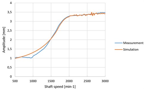
3.1. Comparison of computational model with measurement
The measurement demonstrated that the driveshaft was bent in steady state. The shaft bend is really important for determination of dynamic force from unbalanced mass. The computational model must be adjusted according to this fact. The adjustment was made by shaft geometry, changed to bend state. There is a good accordance between the computational model and the measurement on real vehicle after that adjustment. Computed and measured bending shapes are shown on Fig. 5.
Fig. 5Measurement and simulation comparison
4. Conclusions
The whirling vibration is an important noise and vibration source especially on long shafts in the driveline of a heavy duty vehicle. The MBS modeling approach described in this paper is in accordance with the measurement on a real vehicle. The MBS approach is a valuable tool for simulating dynamic behavior of the driveline. This approach can be used for predicting NVH behavior of driveline in a construction phase.
References
-
Rahnejat H., Rothberg S. Multi-body Dynamics: Monitoring and Simulation Techniques – III. Professional Engineering Publications, London, 2004.
-
Tůma J. Vehicle Gearbox Noise and Vibration. Wiley, Chichester, 2014.
-
Wellman T., Govinswamy K., Braun E., Wolff K. Aspects of Driveline Integration for Optimised Vehicle NVH Charakteristics. SAE Technical Paper 2007-01-2246, 2007.
About this article

This work is an output of cooperation between internal BUT research project Reg. No. FSI-S-14-2334 and NETME CENTRE PLUS (LO1202) by financial means from the Ministry of Education, Youth and Sports under the “National Sustainability Programme I”.
